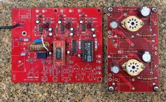
This might take a while

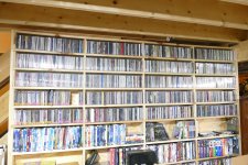
Several times in the past I have gone down the path to rip all of my CDs to a hard drive. I have never finished the task, or even gotten very far. Now after collecting CDs for 35+ years, I have a few. I also have a few computers, so I got a NAS box with 20+ TB of storage, so here I go again.

My earlier attempts used EAC which can take some time to rip, so this time I am using the older version of Windows Media Player which can rip a CD in 2 to 7 minutes. Why the difference in time on unblemished CDs with roughly the same amount of music, I don't know, but I'm guessing Windows background tasks slow it down. I am ripping directly to the NAS box with all the other connected computers turned off or disconnected. Unplugging the ethernet switch from the internet modem does not seem to make a difference and it blocks the Media Player from downloading the song titles and musicians' data.

If I get through the 1200 to 1400 CD's there are 600+ Vinyl records on the bottom two rows of that cabinet and they must be ripped in real time! The DVD movies below the CDs will not get ripped.

Attachments

  • P4020824.JPG
    P4020824.JPG
    596.4 KB · Views: 90

Odd behavior from DIY speaker wire

A friend of mine had a few thousand feet of surplus high quality microphone wire. I've read posts here and elsewhere that say this can be the basis for high quality speaker cables, since mic wire has very good shielding. My friend did the 6 wire DIY braiding method and gave me a couple 8 foot lengths of completed cable, which I finished with some excellent banana connectors, some woven poly sheaths, and heat shrink to tie it all together.

The problem: I've noticed that speakers hooked up with this wire demonstrate some odd effects. It's hard to describe but it's like an intermittent clicking or popping. I have a failed volume control on an old preamp that starts injecting a similar noise when I go past one-third on the dial. It's very short duration and almost subliminal, but once I notice it then it doesn't go away. There's no pattern to it but I think it's related to transients in the music because it's usually at the attack side of a given sound and not the decay. It's almost like tiny bursts of DC are getting injected into the sound.

I'd hate to waste this cable. Is there any kind of test I can run to find out whats happening here, and is there anything I can try doing that might help the sound?

Rotel RB970 BX Mk II crackly output from right channel

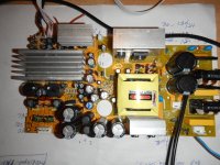
My Rotel RB970 BX mk II has been in use for 20+ years now and has recently developed a crackle on the right channel even when no input is being sent from the pre-amp. A long while ago I did open it up for a general dust and noticed some corrosion (or leaking?) around where the four big capacitors sit on the board. I'll try to dig out those pictures.
Any thoughts on what has suddenly caused the crackle to develop?
Is it likely to be terminal?
Thanks!

Re-indroduction

Hello,

Many years since I've posted here. Had a quick question in another post but the Forum asks I re-introduce myself first. 🙂

General interests that come and go. I've recapped a few 1970s Marantz, built several tub amps from kits (TU-8200R & 8600) and one from scratch, a "Get-Set-Go" SET with way too much 120Hz power supply noise. More recently interested in waveguide speakers and recently completed an Econowave with selenium 220Ti, Jack gill crossover to FiatalPRO 12PR320. .... Many interest, but mostly just restore old MGs.

Looking forward to continuing the learning process. Always lots of fun!

John

Attachments

  • IMG_8380.jpeg
    IMG_8380.jpeg
    393.9 KB · Views: 39
  • IMG_2462.jpeg
    IMG_2462.jpeg
    503.4 KB · Views: 37
  • IMG_3401.jpg
    IMG_3401.jpg
    517.6 KB · Views: 38
  • IMG_2270.png
    IMG_2270.png
    341 KB · Views: 42

headphone driver reference schematics

Hi all - looking for some reference schematics for solid, decent headphone drivers that aren't overly complicated. Would prefer op amps vs discrete design for simplicity.

I'll be building myself a small mixer/headphone amp, and would like to see what some of the better headphone solutions are these days.

I've used the Behringer P2 on lots of gigs and it sounds fine to me, but I'm not finding a schematic easily. Any ideas on this or similar headphone drivers? (this would be for IEMs in particular; I imagine driving cans is maybe harder, because the larger speakers might require more oomph?)

Thanks!
Geoff
  • Like
Reactions: lineup

Dayton ULTIMAX II driver line

I just opened the latest issue of AudioXpress and on the last page there is a PE advertisement featuring all the members of the ULTIMAX II subwoofer line. This includes drivers of 8, 10, 12, 15, and 18 inches nominal size, all with very impressive Xmax specs (up to +/- 28mm for the 18" driver). The VC configuration seems to be dual 2 Ohm for all versions. At a glance this seems like some new and interesting stuff from Dayton and so I thought I would fire up a discussion thread for this new driver line.

If you have news/info on these drivers, or when they become available you have first hand experiences to relate, please post them here!

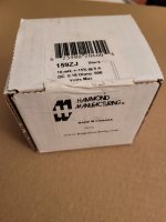
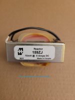
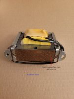
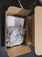
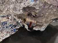
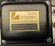
Hammond DC chokes, 159ZJ, 10mH 5A

For sale: Hammond DC reactor, 159ZJ
Date code: 2013-36 wk ; NOS stored in appropriate environment

Edit on Aug. 20 @ 11:53am PT : All chokes are almost sold and transactions pending.


Data sheet: https://www.hammfg.com/files/parts/pdf/159ZJ.pdf?t=1697661944

2 pieces = US$36 + actual shipping
4 pieces = US$66 + actual shipping

Insured parcel via Canada Post every "Thursday only"
Secure packaging included and no handling fee


Thank you for looking!
Joe

Attachments

  • Sealed box.jpg
    Sealed box.jpg
    326.4 KB · Views: 62
  • Open for Incoming QC inspection.jpg
    Open for Incoming QC inspection.jpg
    375.9 KB · Views: 57
  • Clear labeling and in good shape.jpg
    Clear labeling and in good shape.jpg
    282.1 KB · Views: 58
  • Bottom view.jpg
    Bottom view.jpg
    329.2 KB · Views: 56

Philips MCD-908 Speaker fix


Crossovers were delivered wrong on the factory speakers. A quick fix involves just a few simple steps. Your jaw will drop when you hear the difference!

1. Open rear cover plate on speaker. 4 screws.
2. Pull out gently and note the crossover is attached.
3. Solder a shorting jumper over the sand resistor 3R3.
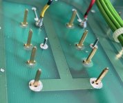
4. Cut thin red solid wire and solder to Heavy red wire's solder pad.

These actions do two things:

1. Over-ride the attenuation blocking action of the 3.3 ohm resistor, thus allowing the mid tweeter to open up.

2. Bypass the awful 1.8uf bipolar electrolytic capacitor that is in line with the ribbon tweeter. The ribbon does not need the cap at all and now it is directly across the primary speaker leads.

The Philips MCD-908 stereo system came out in 2007.

What you will notice when you re-power your speakers is a bright and full spectrum of sonic harmony. Especially in the ribbon tweeter which is now operating as intended!

BMS 4590 coax vs. ND 2080 - how low can they go in a home setting?

Having the chance to buy a pair of 4590 locally, I am looking at how to use them. BMS boasts a recommended 300 Hz lower crossover, which looks great on paper. However, even with the famous 90 x 6 BMS horn that was discontinued about the time the 4590 was launched, frequency response starts dropping at 700 Hz. In extrapolation, this looks like it will hit -18 dB at 350 Hz (!). So unless one uses a custom built very long horn, the 300 Hz recommended crossover will only work with a massive active boost.

I have been reading that most people use the 4590 only down to 800 or 1000 Hz. The treble unit of the 4590 seems to be a poor compromise with plenty of distortion and poor integration into wide horns. Apparently, the Limmer 033 works well with this driver but will only be good down to 1 kHz.
On the other hand, people have been using the lowly BMS 4550 down to 800 Hz in home settings, and a larger driver like the 18sound ND2080 (it's the 1480 without the adapter) should be good to at least 500 Hz while offering reasonable treble (and then there is the NSD with even better treble). I'm guessing here that a 3 in dome will have more oompf down there than a 2 in annular membran...

So if the aim is to have a horn/driver combo that covers most of the midrange, starting at 300 - 500 Hz all the way up to 20 kHz, is the 4590 really worth the trouble?

what in front F5M

Hello all,

i'm working on my F5M an i have to think after....
the F5M will drive my pair MOAP 10.2. actually i have a computer with a soundcard behringer as dac but it's not friendly for the user. (my wife and there is not remote control)
i have to think to preamp/DAC/streamer, i was thinking to buy a Wiim ultra to make this
but my goal is to have emotional engagement from my system, what do you think of this
average all the music is digital CD or demateralised i use average no phono
i listen most of the time pop rock,alternative, piano, and electronic music
what do you do if you were me?

Class-B Output Stage Auto-Bias. No funny business. Just replacing thermal tracking. Please evaluate this approach

Hi All,
Ever since joining this forum class B auto-bias has been on my mind. Thanks to Russel Kinder's RK-Auto200 design.
Russel helped me along massively in solid state design when I was a newbie here. Only at the time I couldn't make sense of his autobias schemes.

Yesterday I think I finally conjured up a circuit that does the job correctly.

I set out to find a circuit that:
  • Replaces thermal tracking. Forming a subsonic bias feedback loop that compensates for thermal drift.
  • Maintains the bias current even with full power 20 Hz signals.
  • Should bring the bias up, such that before the bias feedback starts acting there is no bias current and all remains safe.
  • Leaves no signs of its presence opposed to a passively biased output stage.
Looking back it turns out to operate pretty much like the RK-Auto200 design: (which definitely primed my brain)
https://www.diyaudio.com/community/threads/rk-auto200w-amplifer.367674/
who got the framework from Wlliam Chater:
https://www.diyaudio.com/community/...ontrol-for-power-amplifiers-revisited.367386/

The Framework:
Sensor Circuit -> Peak Detector -> Integrator -> Bias generator


What really cracked my brain was howto detect the bias current under large signal conditions.
It is known that the class B signal currents cross at the bias current. So some circuit should measure what current is present when I(R24)=I(R23).
I guess this is what is referred to as "Zero Crossing Detection".

Orange.jpg


Yesterdays contraption seems to pull it off:

Schermafbeelding 2024-03-14 213836.png


Two current mirrors Q37 to Q42 forming the sensor circuit sense the bias current through 0.22ohm Rsense.
The top mirror subtracts I(Rsense)*Constant from I(J3) while the bottom mirror adds I(Rsense)*Constant to I(J3). This constant is set by by Re and Rsense. The output currents of the two mirrors are added onto Rc to create voltage V(Rc) which is proportional to bias current (and signal current).

Current mirror output currents Ic(37) & Ic(q38) summed to I(Rc) creating V(Rc):

Schermafbeelding 2024-03-14 223318.png


Now under class B signal conditions the magnitude of the V(Rc) peaks are proportional to the bias current. (some kind of personal revelation to me🤣)
This is where the peak detector comes in. I've tried single and dual opamp active peak detectors, all left some artifacts in the FFT. Passive does not. So I Simply implemented it with D11 and C11 to create V(vpeak):

Schermafbeelding 2024-03-14 225113.png


Next V(vpeak) is fed to an integrator (U4 TL072) that compares it to reference voltage Vset. In this case -4V, being the target voltage for Vpeak.
Now the bias current can be defined by Rsense, Re, Rc and Vset. Rsense Re and Rc set the gain of the current mirror sensor circuit, the integrator should make all the rest irrelevant.

The integrator then drives an opto-coupler to engage the bias-spreader. More opto-current results in more bias and no opto-current results in no bias. This should be true even when the output stage is getting boiling hot.

Now the loop is complete and it seems to be pretty sturdy but I'd like to make it sturdier. Unfortunately the bias does drop (10mA or so) when a 100W 20Hz signal kicks in. It never quite gets back to where it was but at least we see integrator trying to bring it back up:


Schermafbeelding 2024-03-14 235834.png


Then there is the issue of loop stability. Depending on the Gain of the sensor circuit, the integrator time constant and C11 (probably many more), very low frequency oscillation may occur. Its damped ok now but id like to know howto properly compensate it. I haven't figured out howto do proper stability analysis on this.


The integrator output current in response to large Low F signal:

Schermafbeelding 2024-03-15 000427.png


The output current dropping indicates the integrator thinks the bias has gone up so it drops and we loose some bias. It seems to still misinterpret large signals for bias fluctuations but only a little bit. The loss of some bias current I attribute to the non-perfect Sensor circuit and the passive peak detector. Perhaps there are other causes. Perhaps it needs one more op-amp after all. Perhaps this is accurate enough. Most important is that the bias doesn't keep falling or shoot up like many of my other tries. Neither does it leave anything sign of existence in FFT's.

Hopefully I can breadboard this in the following days. I'll probably waste more time simulating and considering:
  • Sensing from the Emitter resistors opposed from collector resistors and making the circuit float with the output.
  • Eliminate the opto-coupler and use Q19 and Q20 current sources to control the bias.
  • A transistor based Integrator
As always,
I'd love to hear your thoughts,

Cheers
Ruben
  • Like
Reactions: Hennady Kovalsky

Hello!

Dear forum,

Greetings! I am a musician and hobbyist electronic "engineer". I like projects around microcontrollers, especially, when they are related to music or music instruments. Not afraid of disassembling a synthesizer 😀 But still, quite new to all of the electronic components. Did few POCs around MIDI, LEDs and EL-wires. Have some ideas to implement and need advices and opinions, that's why I am here!

125ASX2 BTL amp in a wooden case

I have some custom made wood amp cases with carbon fiber front and rear plates that I am installing my Icepower 125asx2BTL, and 50asx2btl amps in. When I had the amp modules in a metal case I hooked up the btl to the metal chassis and then hooked up the ground from the ac plug to the metal chassis too.

Would it be OK to hook the btl directly to the ac plug too...the furthest amp module will be within 10" from the plug?

Can I daisy chain the btl wire from 1 amp to the other and then hook the 2nd amp module to the ac plug, or would it be better to run unequal ground lengths from each amp module to the ac plug?

Or is there a better option (without making a new case)...

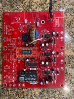
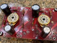
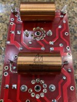
For Sale Audio Note DAC3.1 boards

For sale is this set of AN dac boards. I upgraded to DAC5 and do not need these.
The analog board has the Tantalum resistors, large AN input transformer and the later model AN copper foil caps,
these are not the early ones that were prone to leaking.
This set does not come with the IV transformers however there are several good ones available.

These take the 5687 tubes in both positions and has coax and USB capability.
The input can take 48k & 96k via USB and there are receiver chip mods for higher fs inputs.

BTW- I have my DAC5 setup with a 768k XMOS to i2s and run at 706k which is just awesome.

Asking $300 for the set.

I also have a new unused populated Galahad PS board clone with if anyone is interested for an extra fee.

Attachments

  • IMG_7758.jpg
    IMG_7758.jpg
    468.9 KB · Views: 542
  • IMG_7759.jpg
    IMG_7759.jpg
    864.2 KB · Views: 474
  • IMG_7760.jpg
    IMG_7760.jpg
    809.8 KB · Views: 425
  • IMG_7761.jpg
    IMG_7761.jpg
    866.5 KB · Views: 439
  • IMG_7762.jpg
    IMG_7762.jpg
    504.9 KB · Views: 501

Hello from Indore, India

Hi,

I have been a secret / anonymous reader of this great forum for a couple of years now.

Most of the times had nothing to contribute but had a lot to learn from this amazing community.

Whenever the magic smoke escaped from my stuff I ran to this forum to learn how to put it back.

So far all escaped Jinie's been caught and hope that goes on.

As long as wife and children can keep up with increasing pile of junk ( in their opinion ) I shall hold the post of a certified Audio Stuff Hoarder.....

So long....

For Sale SIT THF-51S TOKIN SIT - A Rough Matched Pair (2PCS), NOS, never used

Hi. Here for sale a pair of THF-51S TOKIN SIT, Rough Matched pair (no matching curve), Condition: New – Open box, Bought directly from Japan one month ago, ebay seller fet-tokyo, known to be a trusty guy, parts, never used, never soldered.

Paid 198U$ + 24.80U$ shipping, total 222.80U$, Change of plan I cannot build the amp I was planning... My lost, your chance to get a pair at the good price...

Asking 150U$ + shipping (should be around 15U$) + Paypal 3.5% fee (or use Friend & Family)

Let me know
SB

Attachments

  • 20240819_132522.jpg
    20240819_132522.jpg
    410.4 KB · Views: 105
  • 20240819_132538.jpg
    20240819_132538.jpg
    514 KB · Views: 106

Do "cooling holes" around a tube really make sense?

Hi,

when looking at 300B builds, some use holes around the socket of the tube and some do not.

The argument made is that these holes will produce air flow around the tube in some "chimney effect". I am sceptical that this has any significant effect, especially if the case is closed at the bottom, but even if not.

Are there any real measurements available that prove the chimney assumption?

Also, the tube has a heater / filament to, well, heat it. So, given a design with some room around it and a grill/mesh above / around it at max, is it even desired to cool it?

Thanks

Metz Connect. SR99SxxVBNN / SR99SxxVWNN

has anybody tried these for single wire to board connection .
Where you have only 1 solder pad to solder wire. I cant seem to find
a one pin connector for single wire. Need something like a one pin one wire,
all the one wire connector's seems to be like b with 2 pins one behind the other.
I want single pin as i don't like to solder wires direct to pcb for easy alterations.
I also find that soldered wires to pcb are prone to failing.
Thanks

connector.jpg

Upgrade Celestion DL10 speaker and sell or strip components and sell seperately

Hi
Apologies for all the newbie posts.

I have a pair of Celestion DL10 to my ears they sound great but I don't think they go for much on the 2nd hand market.

I will be selling them. But I can't make a decision on m, the two options below.

1. Replace the caps, clean check soldering, reseal, check wadding, and replace grill cloth. <£sell?>
2. Strip out current components (drivers, cabinets, crossovers tweeters. All original) and sell them individually. I should say that the caps don't look like they are past it 🤔 <£sell?>

where is the demand for either option? is there such a thing as a Objective view point?

Ta

Sanwu TDA7498E

I made 2 amplifiers using the red Sanwu tda7498e boards that are available at all the usual places. I'm using one with a pair of 2 way bookshelf speakers with 8" woofers made by TC audio and the other with 6.5" woofers and 3.5" tweeters. They both have developed a pretty loud noise floor that I never noticed so loud as it is lately. I can hear the static white noise sound from 8' away when it's quiet in the room. They both hiss even when the signal inputs are disconnected. What would cause this to happen?

Also I remember reading about some popular mods to these Sanwu boards but can't seem to find the thread anymore. If I remember correctly one of the mods was to remove and jumper some diodes but I don't know which ones.

Any thoughts on these Bear Labs SE MosFET amps?

I have an opportunity to buy some Bear Labs Mosfet SE monoblock amps for a decent price. These amps were build by a long time member here, Bear. I believe Bear is gone now, and this is all I can find on the amps on the interwebs: http://www.bearlabsusa.com/NEXT/SPECIALS.html

Does anyone have any experience with the amps? I would use them in Joseph Audio Profile floorstanders. How much would you pay?

Thanks!

2-SE.jpg

Voice coil sounds like it's rubbing against something, but only when it's shorted?

So, I'm having this really weird behavior from a sub I just rebuilt:

I was breaking it in with a sine wave at Fs for the whole night, and at the morning it suddenly started doing a cackling sound, characteristic of a misaligned voice-coil rubbing against the top plate.

I then switched off the amp to see in what direction it was misaligned, but as soon as I switched it off, it would no longer sound like it was rubbing on anything, even if I forced it to tilt with my hands, by applying more force to one side than the other. Seemed very properly aligned.

Then I figured it could only be because of the amplifier being on, I switched it on, and it began doing this rubbing noise when moving the cone.

I took it off from the amp and shorted the voice-coil, and again, it began doing this sound.

So, whenever there's a low-impedance circuit closed on the coil, it does that.

But my question is: WHY?

I don't understand how more damping can cause the voice coil to rub against the walls.

The only thing I can think about is that, when I'm pulling it by the cone with my hands, and the voice coil is shorted, the damping force on the voice coil is misaligned with the force the cone is imprinting on it, and the resulting movement is skewed.

But then again, the weird thing is, that no matter to what radial direction I force it, or tilt it, this rubbing sound never goes away, never improves substantially.

If I force it even more, then another, stronger rubbing sound comes on, making it even look like that only then it's actually rubbing against something.

I don't quite understand why this only began after hours of operation, perhaps because it heated and softened the glues, but the voice coil didn't even felt substantially hot either.

I'm just worried I'll have to rebuild the entire thing just because of this.

And by the way, it's not quiet enough to be ignored, it's clearly audible.

For Sale Luxman MQ68

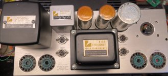
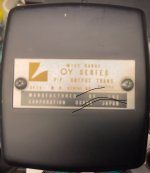
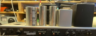
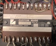
I have this amp for sale. No tubes, but nice appearance.

Output transformer - $200

Mains transformer - $200

Chassis, complete as seen - $200

Complete amp - $550

Shipping at cost.

EU sales only - due to weight.

R

Attachments

  • IMG_1093.jpeg
    IMG_1093.jpeg
    231.1 KB · Views: 181
  • IMG_1088.jpeg
    IMG_1088.jpeg
    113.9 KB · Views: 174
  • IMG_1090.jpeg
    IMG_1090.jpeg
    300.9 KB · Views: 183
  • IMG_1089.jpeg
    IMG_1089.jpeg
    257.2 KB · Views: 193
  • IMG_1091.jpeg
    IMG_1091.jpeg
    490.5 KB · Views: 197
  • IMG_1092.jpeg
    IMG_1092.jpeg
    214.8 KB · Views: 172
  • IMG_1094.jpeg
    IMG_1094.jpeg
    376.9 KB · Views: 176
  • IMG_1095.jpeg
    IMG_1095.jpeg
    463.7 KB · Views: 175
  • IMG_1096.jpeg
    IMG_1096.jpeg
    412.7 KB · Views: 188

Lightweight MEH based on Scott Hinson (DIYRM) design

I'm building a lightweight, portable variant of Scott Hinson's 'MEH' design that he shared on his DIYRM page on Facebook (https://www.facebook.com/DIYRM). The PDF is here: https://drive.google.com/file/d/1nE...lkT3rECpb8WYPMgiS_8pSvRAGxZkbaGmzzkCrsYXF9w8o

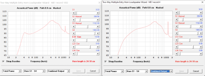
Looking to swap the B&C 10nw76 drivers for 10cl51 (saving nearly 2kg per driver) and the DCX354 in place of the DCX454 he uses, saving another 2kg... a total of 6kg saving!

I used his parameters in Hornresp, but with he 10cl51 specs, and got a plot with similar or better SPL from 55Hz upwards. See image below. Left hand side is the plot from Scott's instructions with the 10w76. Right hand side is my plot with the 10cl51 specs.

I know the 10nw76 has more power handling, but I'm limited to 150watts, which is the max my battery powered TPA3255 amps will supply per speaker. I'm happy to pair with a sub and/or use a bit of DSP to fill in the bottom end (with boost, or psychoacoustics)

Am I missing anything? Any issue crossing to the DCX354 at 400hz, instead of the 300Hz possible with the larger DCX454.

Thanks!

(PS: I know this is heading in the direction of the SynTripP design, but I found Scott's instructions more complete and the rear ports seem to me to be easier to 'play' with as I'm experimenting with different drivers and tuning)

Attachments

  • MEH 10nw76 (L) 10cl51 (R).png
    MEH 10nw76 (L) 10cl51 (R).png
    219.2 KB · Views: 598
  • Like
Reactions: pelanj

Help please making a good 6.5" setup

Hi everyone just joined for this after MANY results on google landing here.

So the story is I have my Pajero aka Montero Sport 2005 which I like, doing sound at the moment.

Here is my budget friendly setup I have:

KDC-BT73DAB head unit
Hertz Cento C165 speakers (front and back) freq 55-7k rears faded to half
Alpine S-S10TW tweeters freq 1 kHz - 22 kHz
In Phase USW10 Under seat subwoofer freq 40-150hz

I have tried many tweeters including the focal ones, anything else but them alpines are way too harsh for my taste even with eq settings spent hours get some songs right then others wrong. These Alpine S-S10TW are perfect for me.
I also have a set of 4x Audison Prima AP 6.5 freq 60 ÷ 5k Hz
Since I have a sort of a subwoofer (not the best but does the job) is it wiser to use the Audisons since they have lower bass and mids up to 5k?
Also, obviously the tweeters are overlapping with the speakers on the 1k-7k range. IS that ok or should I somehow limit the lower range and put a filter for them to start at 7k?
The hertz speakers are very good with bass, the seat subwoofer is set to 60hz and it sounds ok. The sound quality however is just not right to be fair, I had my freelander 1 from 2003 with harman kardon mopping the floor with this. That is what I am aiming in fairness I do not need nor want loud, just SQ. The subwoofer under seat was put there to help with bass whilst driving... That is where bass goes away evaporating.

Ah yes all four doors are properly sound proof, both inside the panel and the door itself with dynamat outer and some soft 3mm inner, not a single rattle anywhere. That part I am confident it's well sorted.

Thanks
Paul

Vias lining a PCB trace - how do they change trace impedance? .. & crosstalk ...?

Hi all,

I would appreciate a bit of insight into this, if anyone here knows:

1. Vias lining a PCB trace - impedance change: How do the GND connecting vias lining both sides of a PCB trace (digital traces in particular) change the impedance of the PCB trace? Since the electrical fields surrounding the PCB trace is altered when adding these GND connecting vias to each side of the PCB trace I would guess that it also alters the PCB trace impedance, however, I have not been able to find any mention of this anywhere ... ? Anyone knows about this (I would also much appreciate a link to a short text describing the optimum way of placing these vias, should one of you have such a link)?

An example of what I am thinking about can be found here:

https://electronics.stackexchange.com/questions/39834/placement-of-vias-to-connect-ground-planes

2. Crosstalk differences: Also, I have been wondering to what extent such vias alter the crosstalk between traces? ... Robert Feranec in one of his youtube videos (a trace radiation simulation without vias is shown from 15:13 - with vias from 16:03) illustrates how these lining vias greatly reduce the radiation from the trace - something that I reckon will also greatly reduce crosstalk:

Login to view embedded media
However, when e.g. using the Saturn PCB toolkit (v. 7.11) the crosstalk numbers appear to be relatively high (and it is not described in the tool kit help whether or not lining vias are considered in the crosstalk calculations) ... That the Saturn crosstalk numbers appear to be high is my "assumption" as e.g. Analog Devices in their layout of the AD4630 EVM board's input traces according to the Saturn PCB toolkit would have a crosstalk coefficient between the two input channels of ~ -116 dB (1 MHz sine wave=~350 ns rise time, 10mm trace spacing, 10 mm trace coupling, trace-to-gnd plane distance 0.2mm, FR-4 board, signal voltage 5V). Which is quite high considering that this ADC is capable of a much lower noise floor. A link to the AD4630 EVM board - just FYI:

https://www.analog.com/en/design-ce...n-boards-kits/EVAL-AD4630-24.html#eb-overview

So I wonder how much lining vias - which are lining the AD4630 board's input traces and also discussed in the Feranec video - alters the radiation from a trace and thus also the trace's impedance?

BTW in searching for this information on Google I found an article on guard rings in microstrip & stripline PCBs. Quite interesting IMHO.

https://cdn.teledynelecroy.com/file...guard_traces_with_optimized_shorting_vias.pdf

If somebody here knows about the above if would appreciate your feedback.

Cheers & have a good day,

Jesper

NAIM PCB pins

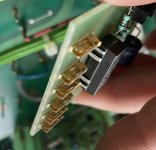
Hi all, I am looking for 10 or so replacement gold Pcb mini spade pins and edge connectors for boards in my Naim NAC 72 Amplifier. Does anyone please know where I can find them? (I’m based in UK / Europe). I’ve hunted everywhere unsuccessfully so far. Thanks for your help. Adam

Attachments

  • IMG_6321.jpeg
    IMG_6321.jpeg
    555.5 KB · Views: 115
  • IMG_6320.jpeg
    IMG_6320.jpeg
    435.5 KB · Views: 118

Tweeter quality

Is there any consensus on what makes a good quality tweeter (other than correct implementation and Crossover design)? Please excuse my lack of knowledge but there is a huge range of products out there. From foil to dome, metal, silk etc. Is a larger ferrite motor preferable to a small neodinium one?

What could I expect if changing an existing tweeter with a marketed as high quality item one of the same electrical specification and am I correct in assuming that even something as the wave guide will have to be taken into consideration at crossover design and can't just be added to a speaker as a replacement later on? Thank you

What speaker should I build next?

Hi All,

I have a small stereo system consisting of an F5 amp, a Korg Newtube preamp, an old Rotel RP1000, and Frugal horn speakers with Fostex 4" full range speakers. I love my home build stereo. It is best when played with records that are recorded the old way with a band around a mic. Miles Davis Kind of Blue is one that sounds best. Live recordings sound great. Anything that is well recorded sounds good. Bad recordings are really exposed. The system's weakness is on the low end. These speakers cannot reproduce full orchestra recordings very well. The problem is not what sound comes out of the speakers, it is what is missing on the low end.
So, what speakers would you recommend that I build next? I need speakers that will reproduce big complex recordings that include a lot of base. I do not think adding a sub will work well with my current speakers. I have the tools and capability to build fairly complex cabinets if necessary. I will not add store bought speakers to my home built stereo. I would get sent to hell for a sin of that magnitude.

I do not have a huge house or an unlimited budget. WAF score will be a factor, but she loves my stereo so far...

Ground loops, interconnects, safety grounds, etc.

In this video he demonstrates the potential that exists in every home between your neutral return and your homes safety ground. There can be several volts, and it can vary based on what is currently drawing power in your home, as well as differ at various locations in your home if you measured it at various outlets. Thought I'd post this as it shows the reason for ground loops, why people incorrectly try to circumvent problems by lifting safety grounds, and why we devise methods like the 10 ohm resistor with capacitor and
diodes that only engage if there is truly a safety fault (see the tubecad "house ground" circuit) to get a audio ground reference that is also safe. Nice short video, for a subject that mystifies.


Login to view embedded media

Come on Hyundai / Kia

I used to think they had a couple models that were tempting but the paint is peeling off now?
Login to view embedded media
And that is on top of the lack of a simple transponder key leading to people's cars being stolen over and over. And don't even get me started on the 'fix' for the brake fluid leaking on a wiring harness being putting a lower rated fuse in so it will blow before the wiring harness catches fire. Shouldn't the leaking part be replaced?

  • Locked
To fuse or not to fuse?

Hi!

Have had a discussion about fuses in the preamp….
My thinking is:
The preamp fuse is dimensioned for the inrush current during start-up - thereby probably largely oversized for the preamp after the start-up period. So what is the purpose of the fuse?

For protection? But the house electrical network has fuses…. Isn’t that enough?

Can you please explain to me why is it necessary to have an preamp fuse? Is the fuse really nescesarry ?

/Anton

SPL Dips

Firstly apologies if this is posted in the wrong place. Please let me know if it needs to be moved.
I've just finished a new speaker build and I'm really happy with them. But in the interest of constantly improving I am using a measurement microphone for the first time with REW.
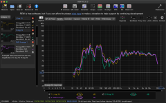
I've just taken a measurement and I see quite a significant dip between 200 and 1000hz. As I'm pretty new to this I am now unsure what to do next to go about getting these more balanced. I am using a JAB5 amp from sure that has a built in DAC so I assume I can make tweaks inside of sigmastudio. Or perhaps the issue is to do with standingwaves inside the enclosure and better padding would help? Any wisdom anyone can impart to get me looking in the right place would be greatly appreciated. Thanks

Attachments

  • Screenshot 2024-08-19 at 17.25.54.png
    Screenshot 2024-08-19 at 17.25.54.png
    193.4 KB · Views: 84

What resistor is this?

Hello everyone!

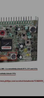
I've been trying to fix a FM receiver and I found this weird resistor. I've found it the receiver it's a blue box that says r22 so I would think it will be 22 ohm but it measures sort circuit. Is this some special kind of resistor or it is faulty and that's why it measures sort circuit? You can see it in the top right in the photo.

Attachments

  • Screenshot_2024-08-19-22-36-07-719_cn.wps.xiaomi.abroad.lite.jpg
    Screenshot_2024-08-19-22-36-07-719_cn.wps.xiaomi.abroad.lite.jpg
    188.2 KB · Views: 136

Bought belt idler roller kit for my deck, your opinion (pic attached)

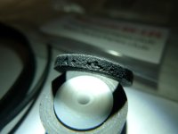
So I have an old Nakamichi BX-125 which was in need for new set of fresh rubber and bought a generic replacement kit on ebay, the 2 belts and roller looked pretty nice visually, but the idler (see pic below) has a pretty poor surface finish full of larger holes, how much will this affect wow and flutter?
It's not a huge deal as it was pretty low cost anyway, but wondering should I give a positive, neutral or negative feedback on this, the seller didn't give any feedback yet which I consider another slight negative as I have already fulfilled my bit of the transaction and puts a pressure on the buyer to give a positive feedback in fear of receiving less than positive feedback in return, most sellers do give a feedback immediately after payment without awaiting the buyers feedback.

Nakamichi BX-125 replacement idler from ebay seller boonpc (happytapes3d).jpg

Attachments

  • Nakamichi BX-125 replacement idler from ebay seller boonpc.jpg
    Nakamichi BX-125 replacement idler from ebay seller boonpc.jpg
    79 KB · Views: 53

Red Rose Rossette 2 phono preamp

Hello friends.
Years ago I bought on Ebay, my Red Rose Music Rosette 2 phono preamp, which I use for MC cartridges, I have been very happy with it, but recently, when it has been running for about 15 minutes the right channel stops working.
If I turn it off, and leave it for 5 minutes, the channel starts working again.
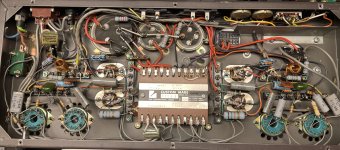
I have opened it to see if it had any cold solder, and my surprise is that I have found it modified, it has changed the operational amplifiers and bridges on the PCB here and there.
I don't have the schematics of this preamplifier and I would like to leave it as it comes from the factory.
Does anyone have the service manual for this preamplifier, obviously I understand that there is a cost involved.

Drivers with Alu Oxidation

I have a pair of Celestion DL10 10" woofers.
They have white oxidation on the Alu driver baskets.

I've wiped away the powder but don't want to go to town on them as the oxidisation isn't affecting the sound of the cones/voice coil etc.
Would the oxidation affect the resale value?

I've decided to strip the speakers down and sell the components as I don't think the speakers as a whole are in demand.

Linn av 5140 tweeter repair

Hello
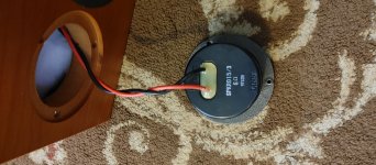
I need to replace the tweeter of my Linn AV5140 speakers. I have attached the pictures of tweeter. I don't know if it is soldered or not. I did some research and found someone already replaced. This is from him
" Finally got the job done with the help of my borther in law (recommend someone experienced in soldering and electrical repair!!) and confirmation on the "how to" from Linn. I will post to help someone else in my position. The AV5140 Linn Tweeter requires the speaker wire to be soldered into the back of the tweeter. Solder wire, then tease and remove strands of wire until it will fit snugly inside the terminals. Solder and seal with non conducting RTV or glue that can be removed if need be in the future"
I still don't understand where to desolder. Any help would be greatly appreciated.

Attachments

  • 20210626_114650.jpg
    20210626_114650.jpg
    1,008.4 KB · Views: 279

Capacitors for testing crossover?

Probably a stupid question and I am not wanting to get into “what is the best capacitor” or “do capacitors sound dramatically different” but ……..

Just about to attempt my first passive crossover and do not have a stock of parts so will be buying everything from scratch so want to keep everything as cheap as possible so I can fine tune if necessary.

So I know it is OK to use Electrolytic Bipolar caps on the parallel part of the woofer low pass circuit, but what about using them everywhere else to test out the circuit. This is as opposed to using polypropylene.

My current parts list is -

82uf (woofer low pass) - Mundorf ECap / Jantzen eLeCap
then 27uf, 18uf, 15uf, 6.8uF, 3.3uf, 0.56uf caps which are a mix of Jantzen Cross Cap and Standard whichever was the cheapest, can I just use Electrolytic Bipolars for these as a starting point? This will save about £40 per speaker.

I guess if it all sounds good I can replace with polypropylene at a later stage.

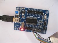
low cost USBi programmer using cypress CY7C68013A board

I managed to use a low cost CY7C68013A as an usBi programmer for sigmastudio.
I had to change some of the stuff in the analog thread https://ez.analog.com/thread/11612?start=30&tstart=0
as the drivers did non install on win7 x64.

you need to create your own cable with 10 pin header and connect it to the board.
GND pin 10 on the ribbon
SDA pin3
SCL pin 1
RST pin 6, from PB0 via a 470 ohms resistor
as shown in the picture. (resistor is 1206 smd)

the download the CySuiteUSB_3_4_7_B204.exe and install.
for win7 and 8 also install the CY3684 DVK package.(cy3684setup.exe)

remove the jumper next to the eeprom and remove the programming cable from the audio DSP card. power up the cypress board. it may or may not find the driver. if not,in the win device manager point to location:
C:\Cypress\USB\CY3684_EZ-USB_FX2LP_DVK\1.1\Drivers and find the driver for your operating system as cyusb3.sys inselected folder.

then power up cypress/cypress suite USB 4.3.7/Cyconsole .
there is a little button showing a folder with doc thumbnail to load a script. find the script in the sigmastudio directory:
C:\Program Files\Analog Devices\SigmaStudio 3.11\USB drivers\x64\ADI_USBi.spt.
press play
then The board will re-enumerate on the USB bus as
Analog Device USBi (Programmed)
put the eeprom jumper back and power cycle the ezusb board. now connect the board to the audio card and check with sigma studio for proper operation.

I will put some hotglue on the wires to stabilize the solder joints...

Attachments

  • IMG_1261.jpg
    IMG_1261.jpg
    849.7 KB · Views: 4,581

New member looking for assistance with head amp for GAS Sleeping Beauty

Hello - New subscriber here. Just getting back into fiddling with my old esoteric stereo equipment. I have a couple of GAS Sleeping Beauty MC cartridges that I purchased eons ago at the GAS going out of business sale. Was wondering if anyone knows of a head amp commonly available today that would be compatible with these cartridges? Many thanks!

3-way side bipole speaker thoughts.

Hi folks,
I'm tempted of reading on bipole projects again, due to the reason one can neglect the baffle step compensation network, thus increase efficiency in the bass region.
I'm aware of the bipole dip of face-back bipoles and I'm wondering if two side midbass speakers would work.
However next come the following challenge - directivity limitation of side speakers. That limits the project to go above 2 way and puts it into 3-way, where a midrange is needed.

Another challenge would be the back location of the speakers, hence their acoustic centers located way back. How does one time align such projects?
What other challenges do you think the designer would have to face?

For Sale Eikona 2 (Pair) EJ Jordan -- Ship Worldwide

SOLD


For sale is a pair of EJ Jordan Eikona 2 loudspeakers in factory condition. They were mounted in a few test enclosures and measured, but that's about it. See the photos.

They are £600 new ($750 USD // €709 EUR)

My asking price is $450 plus shipping. I will ship anywhere in the world.

Please message me your location and postal code for a shipping quote. Thanks!

Attachments

  • PXL_20240623_163720654.jpg
    PXL_20240623_163720654.jpg
    287.6 KB · Views: 66
  • PXL_20240623_163711524.jpg
    PXL_20240623_163711524.jpg
    310.5 KB · Views: 72
  • PXL_20240623_164228966~2.jpg
    PXL_20240623_164228966~2.jpg
    363.9 KB · Views: 62
  • PXL_20240623_163926057.jpg
    PXL_20240623_163926057.jpg
    341.2 KB · Views: 60
  • PXL_20240623_163919488.jpg
    PXL_20240623_163919488.jpg
    404.9 KB · Views: 74
  • PXL_20240623_163912760.jpg
    PXL_20240623_163912760.jpg
    279.1 KB · Views: 62
  • PXL_20240623_163845390.jpg
    PXL_20240623_163845390.jpg
    426.7 KB · Views: 66
  • PXL_20240623_163731813.jpg
    PXL_20240623_163731813.jpg
    282.6 KB · Views: 68

Custom cables and connectors

Apologies if this is posted in the wrong section. Please let me know and I’ll move.

I’ve build a couple of custom bookshelf speakers which sound really nice in my opinion.

One of the speakers has a 4x30 amplifier with dsp. There are two enclosures and each has a subwoofer and a full range drivers.

Where my design is really let down is with the speaker connectors, they feel cumbersome and clunky. I currently have 4 binding posts on the back of one enclosure which I used 4 cables with banana plugs to connect to the other enclosure.

Are there better connectors I could use? How about cables?

Some of my purchased speakers have custom cables and connectors so it’s just one cable with neat small form factor connectors. I think this would be way better but I’m not sure what to search for.

Thanks so much in advance and let me know if more info is required

For Sale F5Pi Voltage Gain Stage + M2 Output Stage (with matched transistors)

Hello All,

Unfortunately I have changed direction and will not be assembling this very nice amplifier. I'm offering everything as I purchased them from the 3 GB.

The F5Pi -- F5P Voltage Gain Stage + M2 Output Stage = Perfectly Integrated
https://www.diyaudio.com/community/...-m2-output-stage-perfectly-integrated.406024/


Group Buy for Toshiba Q-Set for the F5Pi
https://www.diyaudio.com/community/threads/group-buy-for-toshiba-q-set-for-the-f5pi.410439/
F5Pi - GB for US mosFETs, BoM etc
https://www.diyaudio.com/community/threads/f5pi-gb-for-us-mosfets-bom-etc.409406/
Potential GB for original PCB set for the F5Pi
https://www.diyaudio.com/community/threads/potential-gb-for-original-pcb-set-for-the-f5pi.410440/

I will only be shipping to Canada and USA for now and selling the whole lot for what I've paid but I'm including free shipping
Price is -SOLD- (shipping included) + 3% PayPal fees if goods and services is used.

Regards!
Do
  • Like
Reactions: birdbox

3.5Way - XO design and measurements

Hi All!

I am building my first 3.5Way floorstanding speakers. I selected the drivers, designed the enclosure and built a test version, using scrap MDF that I had laying around my shop. The idea was to validate that it is a feasible project. Drivers are:

- Tweeter: Peerless XT25SC90-04
- Mid: HiVi Research DMB-A soft dome
- Mid Bass: Vifa P17WJ-00-08
- Woofers: Generic Aiyima chinese 8" woofers. I will be in the US by the end of the year and will get Dayton Audio DC200-8 8" Classic woofers. Box volume was already defined using Dayton's drivers.

The test box is built and I've just took a few measurements of each driver. I used REW in my macbook connected to a cheap car amplifier and a dayton audio umm-6 calibrated USB microphone, at 1m and aligned with the Mid dome (which is the height my ears will be when listening).
1723743962508.jpeg


I also took measurements in my dedicated listening room, where I will put the speaker. In this case, the microphone was about 2,7 meters away and the speaker was toed out about 15 degrees.
1723746693382.jpeg


Now comes the question. For each measurement, I generated a set of frd files, imported on VirtuixCad and designed a crossover. I expected the measurements to be different, but the differences that I found seem to be a little too much (do not mind the average SPL - i've used different volumes in each measurement).

This is the XO based (alpha draft version 😂) on the in-room measurement (do not mind the fact that it has only one woofer - I measured both woofers in parallel in a single sweep):
1723747634108.png


This is the XO (also alpha draft version 😂) based on the outdoor measurement:
1723747729430.png


I understand that reflections, room modes, etc would change the frequency response (that is noticeable specially below 200hz), but the huge phase difference that I am seeing - which is changing drastically crossover points and driver polarity - is bothering me a lot.

What could be causing this? Maybe the distance between the speaker and the microphone, which changes a lot the time arrival of each driver?

One last info: I am using in-room measurements because the speaker will be there for a long time. I will be using it in this room to listen to music only (for movies, the current setup that you see in the pictures will be used). So i am aiming for a passive XO that is tailor made for my room.

I would love to hear your insights.

Thanks!
  • Thank You
Reactions: GM

My first tuby

After lurking dozens of years here on diyaudio , I decided to build my own riaa tube preamps.
After retirement I recently picked up an old hobby, tubes and amps, combined with a renewed interest in playing vinyl , I acquired some pcb's on aliexpress. One board was based on the Mofi riaa mm/mc preamp, two dual opamps opa1652, two voltage regulators for symmetric psu ,+18V and -18V, and the split active low boost - passive high roll-off riaa network, ready in no time, and sounded quite nice, no hum, noise or other inconveniences, but not very satisfying to listen to.
After some reading on the internet, I got interested in some tube based riaa preamps, in particular the ear384 which seems a shunt feedback design, the Joe Tritschler split passive high - shunt fb active low boost design with unobtainable tubes , and the JL Hood , originally solid state but translated to tubes-mosfet hybrid by me, split series feedback low boost and shunt fb high roll-off design. To that end I acquired two pcb's from aliexpress, one designed for the ear384 design and one for the shure M65 preamp. I wasn't very impressed with the sound of the Mofi ear384, it seemed to have more than twice the voltage output at 20kHz than at 20Hz. Measured with an inverse riaa filter , modelled after the design on Rod Elliot's webpages, with the 1k gain setting resistor altered to 590R , much closer to the original 604R from this design, with all inverse riaa components selected to be within 0.1% of the target values, this fed by a GFG-8015 function generator. So I changed that to the tube-mosfet hybrid JL Hood design:
JL Hood RIAA tubes.png

A few errors , the 43R from the shunt feedback network is connected after the 3.3uF capacitor and the 590R isn't there.
This was a lot better to my ears. Allso measurements with the inverse riaa filter seemed to indicate a much better riaa conformance , with deviations <0.2dB , and a slight roll of at 20kHz, depending on the actual value of the 81.5pF capacitor. The CCS loading the ecc83 is made out of a J112 jfet and a cpc3960 depletion mode mosfet with ca 1mA current. The active low boost riaa feedback network is targeted at around 4mA current. The capacitor parallel to the source resistor can be made into a rudimentary rumble filter. The 6J52P pentode can be anything , ef184 e280f e180f e186f e810f or 6j11p. This my not very tidy test model:
IMG_20240805_095701.jpg

Two gas discharge tubes for ca. 289V stabilized HT and a LM317 for a stabilized 12.6V , the two 6J52P tubes here used run heaters in series, just like the single ecc83. Riaa componenets are selected to match between left and right channel. Because of the feedback design tube matching on gain is less relevant and left and rigt outputs match very nicely.
I allso read much regard for a completely passive design, so I used the shure M65 board to make a complete passive design:
RIAA passive with jfet.jpg

Again a hybrid design , with a 2sk117 jfet cascading into a 6BK7A triode , here cascoding the jfet and the triode would give higher gain, but I wanted to have a line level output voltage. Output is buffered by the ccs loaded mosfet source follower, whereafter the passive riaa network, the values shown gave me the best riaa conformance, though official calculations give sligtly different values. The second triode is ccs loaded with the "mu?" output used as the output. The 825R for the cathode, unbypassed, is to limit output voltage , a LM385Z-adj. would yield more gain, but I wanted to keep the output at approx. line level. This amp allso sounded very nice , though somewhat softer in tone , but absolute no listening fatigue, so much so I have to reconsider playing records because the cost of good needles is pretty inflating my household budget. This is the modified shur M65 pcb:
IMG_20240805_095715.jpg

I couldn't decide which was the better of the above two designs, or the solid state mofi design. I find the tube designs more interesting to listen to, I think mainly because of the looks, with solid state there ain't much to look at, and , despite what people might say, looks count for the listening experience.
To listen to the tube riaa preamps , I allso decided to build an integrated power tube amp, consisting of the standard PP power amp, a tube based tone control, and a builtin riaa preamp.
IMG_20240805_095734.jpg

It's based om el86/6p43p tubes , with a 6BK7A based LTP phase splitter ,ccs in the tail to the -50V ,and a shared ecc83 input tube for L and R channels. The tone control is based on the ecc832 , the AU halve is used as the CF input with the AX halve serving as the actual tone control triode, baxandall type, so no gain in mid position. Both loaded with ccs's made of a J112 and a CPC3960, 4mA for the AU and 1.2mA for the AX , wherev the "mu" output is used for connecting to the power amp input. The riaa preamp is based on the Joe Tritschler passive -active shunt fb design, but with ecc83 tubes, a 2sk208 cascading into the the ecc83 as input, that is ccs loaded with 1.2mA , with the mu output loaded with the passive riaa high roll-of. It's cathode held at fixed voltage by two LM385Z-5 vref's that need only 10 micro A to work properly, and with 1Ohm dynamic resitance no capacitor for AC is needed. The second triode halve , allso ccs loaded with 1.2mA functions as the low boost shunt feedback amp and output to the volume pot. This riaa preamp allso sounds very good, albeit not as "clean" as the other two. The whole amp is fed by a smps , supposedly 300Watt, I got cheap from aliexpress. It's advertised to deliver 300V/600mA, 12.6V/?A , 6.3V/?A and -50V/100mA . Actual output voltages weren't that good. The 6.3V has it's own switcher to make the 6.3V from the 12.6V output. It gave under load only 5.9V and I had to change the feedback resistor value to the switcher to a slightly higher value, it's now 6.23V which seems close enough. The 12.6V was only 12.18V, after allso changing the feedback resitor to the calculated necessary value I got 12.54V , close enough, which allso brought the HT output from 278V to 283V, still quite some lower than the advertised 300V , but since I was using el86 tubes in standerd UL PP design, it was more than enough. Loaded with 5k OPT's , it delivers 18Watts per channel , constant tone test.
The amplifier has no appreciable hum or noise when line level inputs are selected and volume max with ear against speaker cone, but considerable hum when one of the riaa preamps is selected. The seperate riaa preamps have transformer psu's and sound more open than the built-in riaa preamp, but all have equal loud hum with volume at max. Might the smps be the reason for the less open sounding built-in riaa preamp ? I do see a lot of HF dirt on the several supply lines, in the 100kHz till 1MHz range. After changing the power supply input capacitor from the low quality 150uF 400V type to a brand quality 390uF 450V it was less, but still. From scope readings it seems to operate around the 115kHz region and is of the LLC resonant type. The output supply lines have no inductors , like you see in computer psu's. What would be usable types for this frequency and application? The tone control and power amp don't seem to suffer that much from the smps, but I have the idea the riaa preamp has. The tone control and riaa tubes are HT fed by a voltage regulator that brings down the 283V HT to 253V. I tried shielding the smps but that didn't had much effect. Allso, a signicant 50Hz ripple is present on the supply lines , as I understood from reading several papers, caused by the capacitor between the groundplanes of the power input and the supply output. Is there a preferred way of grounding this contraption. I now have a earthed power entry with HF filter to supress HF bleeding into the powerlines and at the supply side a bus ground connected to the power earth entry. Power ground is o.c. not connected. to any of earth or supply ground , except for the capacitor between the power ground and supply ground, which is there for safety reasons as I could make up of reading of the appropriate papers.
And the hum, how could I get most of the hum removed, when I connect the record player through the mofi solid state preamp, no hum at all, when I use one of the 3 tube riaa preamps lots of hum. I have to say that at the normal listening levels of the volume knob , there is no hum noticeable in listening position, only a bit with ear against speaker.
In the end I would say that all riaa preamps, when built to standards sound the same, with the fully active a bit more snappy and the fully passive a bit more airy , and the in-betweens , well , in between. The solid state preamp has no hum or noise issues whatsover, but is uninspiring and a bit flat sounding, probably mainly it doesn't look that good. The tube based riaa preamp are hummy at max volume, couldn't figure out where that comes from, grounding is exactly the same as with the solid state preamp. Noise is allso not a preblem for the tube preamps, though the smps fed riaa preamp seems to suffer a bit in cleanliness, hard to tell. I will at one point replace the smps with a transformer based psu, see how that goes. I am not sure if I hear that right, but smps seems to compress the audio a bit, but than again, might be completely subjective, knowing what you listen to might make you hear things that aren't there. Anyways, all the riaa preamps seem to perform quite well. The mofi ear384 and the shure M65 , the original designs for two of the pcb's I had bought sounded dreadful and very fatiguing, not recommended. I think I like the fully passive design best for acoustic/classical music and the JL Hood active series - active shunt design best for the electrified classic blues, blues-rock etc. music I like to listen to. Any comments on the designs would be appreciated. I am no electronics engineer so there might be a lot to comment on, all designs are cobbled together from bits and pieces I found lurking throught diyudio and the internet in general.
Thanks for reading this travel log into tubesland.
Systux
Life after Frugel-Horn Mk3

After completing and enjoying the Frugel Horn mk3 speakers I'm looking for a new project as my son has claimed them for his new apartment. I must thank everybody involved with design of this great floor standers. First listen was away from the rear wall and sounded far too sharp in the mid range but after some moving around wow, very nice. Bass very good but not over powering even close to wall, top end detailed but not sharp. My son felt the same and now they are gone 🙄.
Looking at the Frugel Horn XL as I believe these will have a smother and richer mid range but without bass overload hopefully. The Sibelis clone looks interesting but without driver cabinet match. Any recommendations on the next build and possible performance compared against the FH mk3.

Attachments

  • 20240804_155121.jpg
    20240804_155121.jpg
    438.3 KB · Views: 202
  • 20240804_165739.jpg
    20240804_165739.jpg
    432.3 KB · Views: 199

Audio garage sale. Fane 15'' fullrange drivers in mint condition (FC152F01-TC)

Originally purchased an OEM pair of Fane FC1502F01 from Thomman music in Germany. Still ub original box and moved on with different DIY projects. The pair is in absolute mint condition!! So many projects. Too little time
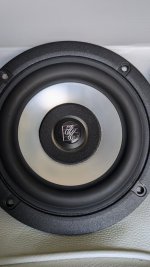
Selling price is 50 USD + Shipping cost via Paypal to local 48 CONUS
Spec is here:
https://www.fane-international.com/downloads/Fane-FC152F01-DS280417.pdf
There's a whole thread from DIYaudio forum talking about this speaker build
https://www.diyaudio.com/forums/full-range/308652-15-range-fane.html


I live in San Diego, CA so local pick up is more than welcome to save shipping cost.
This sale is only for US local. No international shipping.
Thanks,
IMG_9765

IMG_9766

IMG_9769 (1)

IMG_9776

IMG_9859

IMG_9860

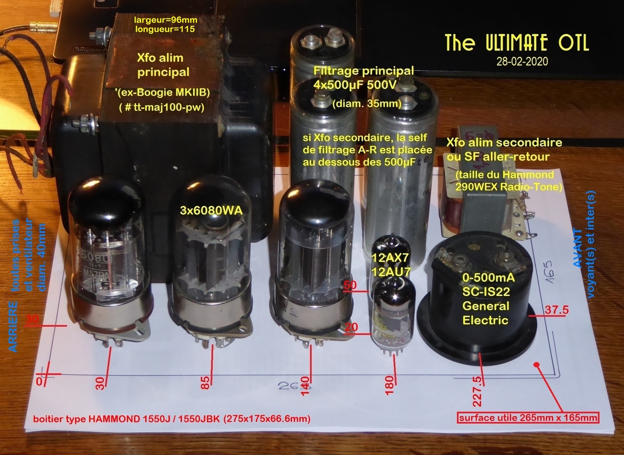
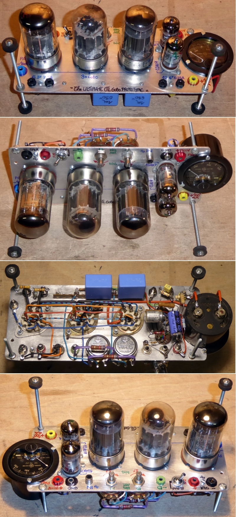
The ultimate OTL6080

Hi All,

I've been off for a while : no time, not much money to devote to... 🙁

My last Audio Hi-Fi build I posted was The ULTIMATE 300B :

19102109190725019416472725.jpg


In the same vein (same format, same chassis) I am building the prototype of what should be (one day) The ULTIMATE OTL6080 :

General layout of what should be a mono block :

u26kJb-P1090409.jpg


Amp section prototype only, for tests and qualification purposes, same disposition as layout :

4GMpJb-U-OTL680-proto-amp-section.jpg


I have to build the PSU prototype now, in the days to come.

Wait and See ! 😉

A+!

Adding a remote control to the SPL Volume 2 preamp

Hello everybody!!

A SPL Volume 2 preamp is coming my way, and I'll be looking into adding remote controlled volume to it.

Looking around, there's this kind of motorized volume control kits: https://www.aliexpress.us/item/3256802832503035.html

They seem relatively straight-forward, but there's not much space inside the SPL preamp for adding the control kit to it:

1723383681355.png


At any rate, would you think this approach is feasible?

TIA!! 🙂
Projects by fanatics, for fanatics
Get answers and advice for everyone wanting to learn the art of audio.
Join the Community
507,547
Members
7,876,319
Messages

Filter

Forum Statistics

Threads
405,695
Messages
7,876,319
Members
507,547
Latest member
Rattle_and_Hum