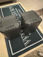
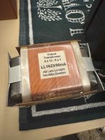
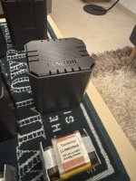
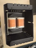
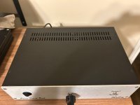
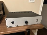
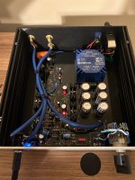
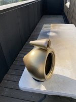
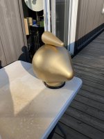
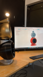
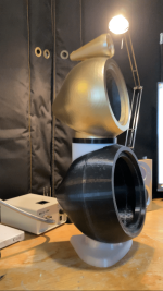
Anyone done business with Heissmann Acoustics lately?

I purchased some construction plans on Nov. 8th. I expected an e-mail with instructions on how to download the plans within 48 hours per the website. I didn't see anything after checking my e-mail including the junk folder. On Nov. 13th I sent them an e-mail at info@heissmann-acoustics.de with the Paypal transaction information. Still no response. So I'm wondering what's going on at Heissmann. Heismann did have an account here, but I think it's been deleted. The last activity was in 2021 and I get an error if I try to PM the account.

Thanks.

Idea: DSP xover to HDMI 7.1

I only know speakers as far as DIY competence goes so this can't be my project, but curious if the concept would make financial sense, and also if anyone else thinks it sounds good.

  • It's a stand-alone board/box with up-to-date digital input options, input of which is converted/mixed to a digital 2-channel stereo bitrate and depth suitable for DSP.
  • That digital stereo signal goes to a miniDSP type of EQ+xover with 3x2+1 output channels.
  • Those 7 output channels are sent to an HDMI output that will be accepted by an outdated 7.1 AVR. Now we have everything to run 3-way DSP speakers and a DSP subwoofer channel, right?

Reason I was thinking of this is that mid-to-high-end AVRs (consumer and pro) can be found cheap-to-free all over these days. Could a device like this be cheap enough to be worth buying for the approx. 100% discount on 7-8 channels of amp?

Coupling capacitor formula

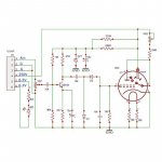
I want to check the value of the coupling capacitor needed for this schematic, with a 6SN7 with a plate resistor of 47K. The potentiometer in the image is actually a grid leak resistor of 220K.

I found this tool online: https://www.ampbooks.com/mobile/amplifier-calculators/coupling-capacitor/

I’m not sure what to use for “output impedance”, as the tube itself will be something like 7K.

IMG_0728.jpeg

Attachments

  • IMG_0727.png
    IMG_0727.png
    15.7 KB · Views: 38

‘Boxy colouration’ or internal reflections through cone

I generally really like the sound of my speakers but if I’m ultra critical I may be able to hear some coloration. This is really only audible to me on some spoken word on BBC on line radio where voices can sound a fraction like they’re in a tunnel. I am probably over stating this and it is also broadcast quality dependent of course. Its really difficult to pin point but for all their faults my previous Stirling LS3/6 BBC Ref didn’t seem to exhibit this to the quite the same extent. At least as far as I can remember.

My current 752 Freedom has one rear port and 3 front ones.

How would you go about trying to find out whether this is simply a result of the driver construction/xover or internal reflections through either the ports or the mid/bass unit itself?

If additional internal damping coild be the solution where would it most likely make sense and what material would be best?

Thank you

https://i.postimg.cc/YS9H51Mk/20230503_211023.jpg

https://i.postimg.cc/Qdb9gWdf/20230501_112519.jpg

For Sale 0.05% and 0.1% precision capacitors

I got those caps more than 2 decades ago and used them only for measurement compairments when sorting out 1% caps with my less precision capacitance meter.
Electronic Associates Inc. hermetically sealed capacitors.

6pcs 1uF, 0.05%, 25Vdc, 39.4x25.6x25.6mm (2x0.5uF precision matched by AE)
8pcs 1uF, 0.05%, 25Vdc, 44.5x25.4x15.9mm
8pcs 9uF, 0.05%, 25Vdc, 76.5x54.4x27.2mm
13pcs 2nF and 14pcs 18nF, 0.1%, 25Vdc, 14.4mm diam, 54.4mm long

Please let me know if you are interested in any of those, you pay only for shipping and pay for the caps whatever you find proper, i will donate that sum
to DIYaudio

Still up for sale

Attachments

  • DSCN1502.JPG
    DSCN1502.JPG
    203.6 KB · Views: 362
  • DSCN1498.JPG
    DSCN1498.JPG
    333.4 KB · Views: 363
  • DSCN1505.JPG
    DSCN1505.JPG
    295.1 KB · Views: 367

A new do-it-yourselfer

I am an amateur brewer, I do music engineering, I listen to music and I make amplifiers. I just joined you and I am here to learn your knowledge. Because I have a plan to make an amplifier. I found a schematic attached to a post and decided to make it and of course I have no knowledge. I would be happy for your help and please excuse my English. What do you suggest instead of 2sj74, I could not find it in my country and did you combine this JFET to N channel instead of P channel? I did not understand the R112 resistor? The outputs are N MOSFET, why is the input P JFET? Can't we make them all N channel? Also, I did not fully understand is this 24 0 24 source or 0 24? Thanks in advance.

Attachments

  • F8 First watt.png
    F8 First watt.png
    17.6 KB · Views: 102
  • Ekran görüntüsü 2024-09-25 022049.png
    Ekran görüntüsü 2024-09-25 022049.png
    50.3 KB · Views: 102
  • Ekran görüntüsü 2024-09-25 022133.png
    Ekran görüntüsü 2024-09-25 022133.png
    44.3 KB · Views: 110

High current supply for testing

Thinking about getting a higher current supply for testing amplifiers under load. Car amplifiers that is, 😉.

I have a prism sound dscope and am able to do power sweeps etc, been doing it for quite awhile.

I'm constructing 4 banks of a bit over 1000W capable 4ohm loads that are fan cooled. I'll be able to parallel the banks up later. They are 45ea of the vishay 2.2 ohm 25 watt resistors. 9 series/5 parallel fwiw. Should be pretty nice.

I currently have a tekpower 15v 60A (and 5A 30v tekpower for debug). Kind of limited for the higher power amps I'm repairing, especially if I want to test below four ohms.

Spark Usina makes an interesting offering out of Brazil. Will do 220A at 15v. Decent price.

I know everyone will suggest this and I've built server power supplies and have one. I haven't figured out how to bypass the overvoltage. So it's only good to 13.8v which isn't ideal. Pretty common to hit the overvoltage barrier with sever supplies I believe.. I used this one before I got the high power tekpower.

I have access to 220v 20A at my workbench fwiw.

Wondering if I'm missing another option? Would like to be able to do 200A at 15v at least. Needs to monitor and display both current and voltage too.

--------
Ended up buying x3 of HP dps-1200fb hstns-pd19 and modifying... This thread became kind of a how-to.. 🙂

PSU for class A amplifier

Greetings!

Together with a good friend of mine I am planning to build a class A amplifier.
This amplifier we are trying to build it supposed to be something special.
In this regard we did our best in order to achieve our goal.
So,...we started to design our own PCB's and first of them is a DC regulator based on LM338T and a CRC filter.
I will upload here a image with it just to know your thoughts.

The DC regulator it will be placed on the same heatsink as the amplifier board. So don't be distracted by their own small heatsinks.

Enjoy !

Attachments

  • Untitled.png
    Untitled.png
    72.8 KB · Views: 108
  • Untitled0.png
    Untitled0.png
    53.4 KB · Views: 103

WTB 2X used GRS PT2522-4

I'm in need of a pair of GRS PT2522-4 for a current project I'm pursuing. They don't need to be cosmetically perfect but functionally perfect is a must. The tweeters must also be located in Canada for ease of shipping and tracking abilities. If you have a pair in excellent but not necessarily cosmetically perfect condition that you'd like to unload, please message me with your expectations. As these are for testing/experimental purposes, I, like anyone in Canada currently, would like to keep things as affordable as possible within the confines of fairness to the seller and I.

Got some, lemme know.

Shane

4-channel Aleph J questions:

I'm in planning process of a 4 channel Amp for active speakers. The idea are to use a
  • miniDsp Flex Eight
  • a 4 channel Aleph for driving mid (Monacor SPH-165KEP, 89db in a closed 10l box) and tweeters Monacor DT-25, 95dB).
  • a 2 channel Class-D 100W for 2x 10" subwoffers. (another project, just for information)

Powersupply: I'm considering
2x Nelsson bipolar power supply, with 1x 600VA transormator (or 2x300)
4x Nelsson bipolar power supply, with 2x 300VA transormator (or 4x150)
It will depend on space in the chassi when everything else are in place.

Some questions regarding the Aleph J:
  • Will the miniDsp Flex Eight be able to drive the Aleph without a pre-amp?
  • Any recommendation for a chassis that can accommodate 4x of Aleph J (both to space and heat)?

Elac DS-S101-G network streamer

Free.....with Free U.S. shipping (lower 48)

I've been using this streamer for years and it's a great sounding piece that works with a free app from roon called 'essentials' it also works as a roon endpoint if you already have roon.
Here's where you need to pay attention.....since I upgraded my phone (S24)
the app no longer connects properly to the router (sometimes it does, then drops easily others not at all) I've tried everything possible (for me) and just decided to get a new streamer (cambridge CXN V2) that I'd been eyeballing that was half off for refurbished unit (1 yr warranty) on the cambridge audio ebay site. The new Cambridge unit works flawlessly so that rules out the router.
I don't know if it's actually the phone or the unit....tried full reset to no avail. Support for this app from roon is non existing and elac isn't much help either so you'd be on your own......If you already have or planning to get full roon it may work no problem with that.....or it may just be you'll set it up and will work flawlessly on essentials.
Worse case scenario if it is bricked (and not repairable) the case is really nice and one could probably gut it and fit a raspberry pi inside.

To give anyone interested a fighting chance I'll collect names (pm me) for say a wk and pull from a hat at the end.

Free/Free shipping (lower 48) is about giving something back to the community.

Bob

Attachments

  • 20240918_143716.jpg
    20240918_143716.jpg
    625.4 KB · Views: 94
  • 20240918_143707.jpg
    20240918_143707.jpg
    603.2 KB · Views: 100

Is it time to get more organised with 3d simulations for loudspeaker design?

As we can see in several current threads running 3d simulations to support speaker design is growing. Unfortunately the insights they bring are scattered all over the place and missed by most. Should we collect them and present in a coherent form that allows people to confirm the results and add to a growng body of work?

There is a current thread on approaches to on-wall speakers (happy to make a contribution). There is little on the vibration of cabinets (happy to make a contribution). There are threads on the details of ports (happy to make a contribution but not immediately). There is quite a lot of existing work on horns/waveguides. There is a current thread on speaker/baffle shape. There is a little bit on room acoustics. Etc...

A related topic to presenting and discussing the insights from 3d simulations is how a hobbyist can generate 3d simulations of speaker designs using freely available open source tools in a reasonably efficient manner. There seems to be a remarkably low level of activity and I am guessing it is because people are unaware of how to do it. Of course many have no interest in this sort of thing as part of their hobby but I suspect the number of people with an interest is larger than it currently seems.

Snubber board for IXYS SOT-227B diodes

Hi All,

I have built a couple of amps in the past using either the GPBC block type diodes or the PSU V3 diodes from the store.

I wanted something "fancier" than the block rectifier without going through the hassle (and cost of needed parts) to assemble the diode boards from the store.

So I cobbled together a small prototype board as attached mainly to confirm the footprint etc.

The SOT-227B should fit the perforated base plate of the shop chassis.

I have attached some pics that should be pretty self explanatory.

The boards are 26x39mm , 1,6mm thick and 1oz copper only on the test run and admittedly the resistor positionning is somewhat dodgy, I got lost in the 0,01mm grid in Kicad...

In someone is interested in a couple of boards for a built and willing to give me some feedback I'd happily send a couple of those out.

If this raises enough interest I could offer a group buy (of slighly modified boards in 2mm and 2oz) incl. the IXYS diodes for around 50% of the price at the major distributors (fellow DIYer has lifetime stash of those for whatever reason).

Looking forward to you thoughts.

EDIT: Pictures comming in 2nd post, forgot to crop them...

Attachments

  • VBO40-08NO6-1549538.pdf
    VBO40-08NO6-1549538.pdf
    534.9 KB · Views: 150
  • IMG_20210419_103804_01_768x1024.jpg
    IMG_20210419_103804_01_768x1024.jpg
    146.8 KB · Views: 365
  • IMG_20210419_182015_768x1024.jpg
    IMG_20210419_182015_768x1024.jpg
    158.3 KB · Views: 336
  • IMG_20210419_182304_768x1024.jpg
    IMG_20210419_182304_768x1024.jpg
    150.7 KB · Views: 319
  • IMG_20210419_182411_768x1024.jpg
    IMG_20210419_182411_768x1024.jpg
    127.7 KB · Views: 332
  • IMG_20210419_183437_1024x768.jpg
    IMG_20210419_183437_1024x768.jpg
    168.2 KB · Views: 326
  • IMG_20210419_183547_768x1024.jpg
    IMG_20210419_183547_768x1024.jpg
    162.7 KB · Views: 285

Measuring & comparing guitar - bass pickup frequency response - does "this" sound reasonable ?

as with measuring loudspeakers with REW/TrueRTA/etc. and a mic by:using an exciter coil as described at Github as 50 turns #26 wire on a single coil
(Strat/ Jazz bass bobbin) - there's a series resistor (value?) with the exciter coil and the coil driven by an amplifier

The exciter coil is placed against the pickup under test. The output of the pickup is terminated with a load like it would see from a guitar's pots and external amplifier input impedance. (some cable capacitance might be added to evaluate effect))

The pickup under load's output is fed to the audio interface to be evaluated by swept sine.

OK? - any mods to the exciter coil? - how much R in series with the exciter coil?

I need to find a cheap domestic source for the bobbins.

Altec 416-8B Midwoofers: Recommended Subwoofers

I sent my pair of GPA Altec 416-8B to Troy Crowe for testing. https://josephcrowe.com/blogs/news/altec-416-8b-in-100l-sealed

As you can see, due to the sealed box size at around 70Hz they probably won't play at much above 80db, if that much, at 11 feet away.
I thought of using a pair of these subs. Rythmik Audio servo subwoofer 12" F12SE Signature Edition

I'm well aware that the 416s were designed to be used in larger and ported cabinets. However, when these were built in 2016 I was following the lead of fellow diyaudio.com member Gary Dahl, who in order to minimize distortion levels put the 416s in those sealed 3 cu ft boxes to limit their low end response, and then extend system response using Acoustic Elegance subs/passive radiators. https://galibierdesign.com/wp-content/uploads/wa-trip_gary-d.jpg

But Gary mentioned here last year that he only uses the subs for home theater. For music, he claims to get ample bass response from room gain due to fortuitous speaker placement. I doubt if I will get that lucky in my room, hence my questions about using the Rythmik subs.

Until Troy Crowe builds the rest of the system-probably using this horn 3D CAD files --- Horn No.1994 -- ES450 Biradial for JBL 2446 2" Throat -I will have no idea how well the Altec midwoofers and the Rythmik subs will sound together.

I guess my main concern is if there will be any big tonality differences between the 416s and these subs if I'd have to cross at around 80Hz. I suppose the only way I could cross lower would be if I was satisfied with moderately high SPLs (~ 86db?) from the Altecs at ~ 70Hz in my 2660 cu ft room, however likely that would be. Equal-loudness contour - Wikipedia

Choosing a "sound quality" sub for 40 liters sealed

I wish to step up from my two sealed DCS205 8" subs. They do a fine job down to ~27Hz in room, but surely they aren't quite endgame. I'm going for two subs again, around 40 liters per box, under 1000€ in total. I prefer sealed with DSP (MSO is great) and I do appreciate response down to 20Hz even if the content is scarce - shouldn't be a problem, considering my experience with the 8 inch subs.

There seems to be plenty of nice options for the drivers, but it's difficult to pick one in the absence of Klippel reports or even repeatable HD tests.

Browsing for subs with a strong motor, reasonable Xmax and low end extension I landed on the RSS315HO-44, which seems to reach very deep naturally (Fsc/F10 36/22 Hz) and scores even better in HD at hifi-selbstbau than the highly praised SDX12 (another great option, though expensive). @mayhem13 has mentioned the HO-44 making noise in high SPL use which might not be my case, but it does make the HF-4 a more reasonable alternative. It doesn't quite have the natural low bass at 45/26 Hz, but not bad either, and scores almost as well in HD.

I then wondered if I should go for two 10" units instead for force cancellation. I browsed loudspeakerdatabase again and came across the Peerless XLS10 830452 which seems like a very well regarded unit. It doesn't model very deep at 49/34 Hz, but the Qtc comes out to just 0.479. Now, I don't know if there's a significant benefit in "natural" low end extension - surely there's some benefit in having the impedance peak where output is most required - but it occurred to me that the low Q "allows" adding mass to the cones. 30g extra gives them a Qtc of 0.626 and similar extension to the HO-44 while requiring less amp apparent power overall. Seems like a cool idea, but no idea if it's worth the trouble. SW26DBACs would be another commercially proven choice for dual opposed and no extra mass required, but looking at the AudioXpress Klippel results, I feel like the cost isn't quite justified.

Next I remembered people praising low loss suspensions for "sound quality" or "chest slam" - my alternatives so far fare pretty poorly in that regard. I browsed again, and came across the SB34SWPL76, which models similar to the HO-44 while having a lot looser suspension. Not a fan of the cone to frame ratio, but it's not a significant problem. There's little data on the performance, but it does have me curious. I wasn't surprised to also find stuff like Wavecor, Scan-Speak or Peerless NE series when having the criteria for Qms or Cms. If I could find the Klippel proven 32W on sale, I might just splurge on those...

Any suggestions appreciated, though I don't see much use in "I've used X and it sounded good" 🙂

Musical Fidelity V Link

I have a Musical fidelity V Link USB to SPDIF converter. No matter which Dac or which computer (Mac or windows) I use, the output locks only at 48khz. All my music is 44.1khz so the highs sound rolled off in this situation. It's the V Link 96khz model and I don't think it has any drivers for either windows or Mac. When I connect the unit for the 1st time, windows automatically installs it. Tried changing the sample rate to 44.1khz in the Audio Midi set up but insoite of everything the Dacs lock the sample rate at 48khz. Please let me know if there is a solution to this. I am unable to reach Musical fidelity support from their website to check on the issue.

Screenshot_20240926_004706_Samsung Internet.jpg

bias resistor failure following rectifier destruction

I have an old diytube getsetgo single-ended amplifier. It uses a 6.3V valve rectifier that shares a heater with one of the output valves (6A3). The rectifier valve came to some cataclysmic grief in terms of a cracked envelope. The design uses a cathode bias for the output stage. The bias resistors on one channel then burned up and the bypass capacitor got a hefty bulge. I've replaced the resistors and cap on that channel and there is still no sound. What else do you think got worked when the 'event' happened? Hopefully not an output transformer!
Thanks for any thoughts.

4" Full Range Transmission Line - Aucharm speakers

Hi guys!
I'm totatlly new in this field, I have done some research to learn the best cabinet I would build for my pair of chinese speaker 4" Aucharm DG-403 (1PCS 2019 New Aucharm 4'' DG 403 Full Range Speaker Driver Casting Aluminum Frame IIR Surrouding Mixed Paper Cone 4/8ohm 25W|Speaker Accessories| - AliExpress) which doesn't have many technical information on the store . So far, I found the TL more interesting, locazating the speaker 1/3 of the legth of the tunel to avoid the dip. So I used python to calculate dimensions given a design that I liked. According to the store the Fs is 72hz, so I end up with these two cabinets, the left tunned to 72hz and the right tunned to 50hz. I got a TDA7377 amplifier and a preamp with ES9018 decoder DAC with 12AU7 tube used probably for buffering. Every sigle piece of this system I found doing researches on youtube and forums, I'm completaly new in this field, therefore, I would appreciate so much any suggestion.

50.png


72.png


Cheers from Brazil.

Parasound NewClassic 2125 paower amp - Audible physica transformer hum - any suggestions?
Title typo - PHYSICAL transformer hum.. oops.


I'll be having a look the hum from my NC 2125 soon-ish, so thought I'd get any advice and suggestions from more knowledgable people than me.

I've tried it in a couple houses, with a Audiolab DC blocker, and it's the same in all cases - An audible vibration hum from what i can only assume is the transformer. Certainly sounds like it anyway. This is accompanied by a hum from the speakers, it's been a while since I used it but from memory it's a similar frequency. The speaker noise is low enough that the gain level can be reduced on the back of the amp such that it's barely audible, but all info helps eh.

It's been mild enough that placed in a storage room next to my listening room the last few years i just don't notice it, but now it'll be going in the living room in a new house it's audible enough to hear (and annoy) on quiet days.

Me: I'm capable of identifying parts, replacing larger components (SMD aint my level yet really) and have a very basic understanding of how an amp works, though not to the point where i can say anything more than 'the round thing is the transformer and the big caps are probably the filter caps'. I'm confidant and safe working with mains equipment.

So, at some point I'll be opening it up - what would you suspect? Transformer replacement? I don't know how old the amp is, but it's been about a fair while. Possible the varnish-like compound on the windings has decayed enough to allow it to vibrate?

Somebody a while ago suggested replacing the filter caps - this would be a cheaper easier first step, but I can't quite remember who suggested it and why, so thought it worth asking you who know.

So - any ideas would be really appreciated, where to start, common causes of such a hum, and potential fixes and their likeliness of being the cause.


Thanks for reading,
Jon

Design help request from a mate

My mate wants some help with his sound proof practice room and I want to make sure I'm on the right track with my advice to him.
He's a muso and needs to practice for a couple of hours each evening and more on the weekends when not doing gigs. His playing sax disturbs his wife who works from home.
I'm next door and I can hear him strangling cats when I'm in the kitchen also.
He is currently using his steel portal framed - steel clad shed and wants to stick build a small practice room inside it, but he also wants to be able to record his practice sessions to share with his music teacher and do demo tapes etc.
He is a carpenter so no problems with construction.
I've suggested framing up and cladding the outside with thick MDF and stuffing the space with rockwool or acoustic FG but not lining the interior with board, instead using a sound transparent heavy fabric to reduce bounce and reverb.

I've also suggested the usual practice of unequal dimensions and following the angle of the sheds roof.
Am I on the right track there?

Tuner's ears and the Western Electric 300B

Tuner's ears and the Western Electric 300B​

September 22, 2024 (Google Translated from MR Ohashi's Bolg)
I heard a very interesting story today.

At the request of an old friend, a piano tuner came to Nagoya for work and said he wanted to hear how old Tannoys sounded with a Western Electric 300B, so I invited him over.
Tuner's ears and Western Electric 300B_b0350085_21510126.jpg
By chance, I had just finished checking the characteristics and aging of PSVANE 300B to Western Electric 300B, so I thought it would be a great opportunity to interview him and find out how a sound professional working in a different field from us could distinguish between the two, which are both 300Bs but have a price difference of more than 10 times.

The CD he brought was Chopin by Pollini .
Tuner's ears and Western Electric 300B_b0350085_23052909.jpg
First, I compared the PSVANE 300B and Western Electric 300B specifications of the SV-S1616D, then did the same comparison listening test with the SV-91B. The volume is exactly the same, and the output is just under 1W, but the sound is quite loud on the Autograph.

When I was asked how I would express this difference as an audio expert, I replied that the Western sounds clearer because the overtones are well-ordered, do not clash, and have a more relaxed sound.
Tuner's ears and Western Electric 300B_b0350085_21510116.jpgThen, that person said,

"The reason why we tune pianos by human ears rather than a digital tuner is because tuning each and every note individually is not called tuning. Our job is to adjust the sound that is created when the hammer strikes the strings, the soundboard amplified, and the frame supports the sound. If you simply tune each string, the overtones will clash and make the sound muddy in a certain frequency range, or the volume will drop and make it difficult for the audience to hear. That's why we don't just play a single note, but play all 88 keys to find the overall tone of the sound; in other words, we try to adjust the tone and bring out the best in it. It's more like not only listening with your ears, but feeling the vibrations transmitted from your fingers with your body."

" he said. And

"In that respect, the sound of the Western 300B is very natural and comfortable with few dissonances. Actually, the sound of this CD is unnatural from around D#7 onwards, and the harmonics in the high range are slightly distorted. The cheaper 300B seems to compensate quite well, but the Western is more natural and the peak of the harmonics is much suppressed, although not completely

." He also said that the difference between the S1616D and the 91B is "the weight of the left hand", which was very impressive.

On my way home, I asked if they could tune my upright piano, and they said, "Your instrument has already been accustomed to a certain sound by the previous tuner, so you should not change tuners halfway through. The unique "sound" that has been created over time will die." I had never directly asked him about the work of tuning pianos, but I was impressed by the fact that we have a lot in common, even though we are in different industries.

SONY CX20017 and CX20152 Audio DAC Production

I don't need to introduce SONY company too much. He is the creator of SPDIF. I am unable to obtain the first generation CX890 from SONY. Because people who own CX890 are unwilling to sell. I can only purchase CX20017 or CX20152. Currently, few people in the world make fully balanced CX20017 or CX20152. You can feel different here. He is a truly balanced structure. At the moment when the sound was playing, I was attracted to him. The sound is very clean and full of musical sense. These chips will take you back to the 1990s.Now share with everyone.You will get his PCB at a very low price. But he is in China.If you are a friend of the European Union. Please provide the IOSS number, which consists of IM and 10 digits. The mailing time is about 10 days. All PCBs consist of four parts: audio input board, format conversion board, DAC decoding board, and power board. You can play app content through a Bluetooth chip (purchased in China, manufactured in Shenzhen), or use CS8412 coaxial to play CD content. COMBO384 can also be used to connect to a computer for playback, and there is also an external input IIS interface for connecting to Philips turntable playback. I will provide Taobao product connections. You can use Taobao's overseas warehouse to purchase. If you need assembly instructions and BOM list, please send an email: 410746700@qq.com,My store address: hikvocal.taobao.com
IMG_4283.JPG
IMG_4285.JPG
IMG_4286.JPG
IMG_4287.JPG
IMG_4288.JPG
IMG_4289.JPG
IMG_5148.JPG
IMG_7513.JPG

Tuner meter and stereo signal light on Sony STR-6045

Hi everybody,

I have a strange problem that does not make any sense to me and I thought I could use some help from the members of this wonderful forum.

I did quite some work and learning on this little receiver (Sony STR-6045) and it is sounds amazing now. But strangely after a day or two after putting back the cover, the radio signal meter just stops working and after a week the stereo light will just light up in between stations. One evening, things were back to normal and the next day, it was behaving like this again.

Every time I remove the cover and take some measurements (good stations will give about 130 mV on the stereo light), it will start working again after 2 minutes! And it will keep working for about another 2 days with its cover on.

What I did so far:

  • Changed the stereo incandescent light to a LED (see this post)
  • Verified that the needle of the meter was not stuck
  • Changed the electrolytic capacitor on the tuner meter circuit thinking it could have a problem charging.
  • Moved the receiver to different locations in the house in case all of this could be caused by weak signal.

I usually start by posting the circuit but since it is so weird, I just want to know if any one has ever seen such erratic behaviors.

Narsis / Kaneda MosFET Amp built

Narsis / Kaneda mosfet amp

Today I finished both channel of this little mosfet amp.
I am very-very happy with the result (with the sound).
Typical relaxed mosfet sound, laid back, relaxed, open mids (without any muddiness) and with great authoritative bass.
Warm tube like sound. More like SE type.
I do not have scope and other stuff to take a measurements! Please do not ask.
I will post the layout, the circuit etc. In case anyone interested to build it.
Soon I will post some picture of the built amplifier also.

Attachments

  • Narsis stuffing.png
    Narsis stuffing.png
    31.3 KB · Views: 1,109
  • Narsis 1.JPG
    Narsis 1.JPG
    30.4 KB · Views: 1,130
  • untitled Mod.JPG
    untitled Mod.JPG
    18.2 KB · Views: 1,054
  • Narsis Szines.JPG
    Narsis Szines.JPG
    19.6 KB · Views: 394

ARC SP-10 power supply voltage regulator problem - output is shorted to ground

See attached schematic.

Here's my problem: VR2 and VR3 work fine, but VR1 only produces ~4v measured from its output to its return line. I checked the resistance and it's showing 0.7 ohm from output to return, all others read high. Based on the attached schematic, what's the most plausible explanation? It's possible I overvalued one of the circuits, so assume components could have failed due to that. What could "fail open" and create a path to ground?

Attachments

DAC729 Audio DAC Production

DAC729 is one of the forgotten DACs, and it is the predecessor of PCM64. I think many friends like his voice, he is a real 18BIT chip. With 18 input pins, it has a fast speed, and due to its fast speed, the low frequency is very loose. I think I am very lucky. Can purchase 2 brand new chips. I made it.Now share with everyone.You will get his PCB at a very low price. But he is in China.If you are a friend of the European Union. Please provide the IOSS number, which consists of IM and 10 digits. The mailing time is about 10 days. All PCBs consist of four parts: audio input board, format conversion board, DAC decoding board, and power board. You can play app content through a Bluetooth chip (purchased in China, manufactured in Shenzhen), or use CS8412 coaxial to play CD content. COMBO384 can also be used to connect to a computer for playback, and there is also an external input IIS interface for connecting to Philips turntable playback. I will provide Taobao product connections. You can use Taobao's overseas warehouse to purchase. If you need assembly instructions and BOM list, please send an email: 410746700@qq.com,My store address: hikvocal.taobao.com
IMG_3793.JPG
IMG_3794.JPG
IMG_3795.JPG
IMG_3796.JPG
IMG_3797.JPG
平衡流程图英文.png

USB to coaxial all-digital converter circuit - what's required?

Background: I want to use my MiniDSP 2x4 to perform EQ duties, but I don't want to use its DAC. I want to take the digital signal from the USB output jack and turn it into either coaxial SPDIF or balanced AES/EBU (could also do optical I suppose).

Does this require a specialized IC? I don't totally understand the differences in format across the different cable types.

I know I could order one for cheap, but I thought it would be a fun project to build the converter myself.

AD7846 Audio DAC Production Record

For HIFI friends around the world, I love old chips the most. And we will never accept surface mount resistors and capacitors during production. Because for retro sound, there is nothing more perfect than direct insertion resistors and capacitors. I have produced almost all the chips that DAC can find. I spent a lot of money buying chips. But I think it's very worthwhile. Because I like music. I am looking for music that can inspire inner emotions. I also made AD7846 while completing the production of AD7546. I like the sound of parallel chips. I accept music with emotions. I like the speed of parallel port chips.Now share with everyone.You will get his PCB at a very low price. But he is in China.If you are a friend of the European Union. Please provide the IOSS number, which consists of IM and 10 digits. The mailing time is about 10 days. All PCBs consist of four parts: audio input board, format conversion board, DAC decoding board, and power board. You can play app content through a Bluetooth chip (purchased in China, manufactured in Shenzhen), or use CS8412 coaxial to play CD content. COMBO384 can also be used to connect to a computer for playback, and there is also an external input IIS interface for connecting to Philips turntable playback. I will provide Taobao product connections. You can use Taobao's overseas warehouse to purchase. If you need assembly instructions and BOM list, please send an email: 410746700@qq.com,My store address: hikvocal.taobao.com
IMG_3890.JPG
IMG_3892.JPG
IMG_3893.JPG
IMG_3894.JPG
IMG_3895.JPG
平衡流程图英文.png

Living/loving the hifi life!

Hi, there. I am focused on tubes, open baffles, single driver, full frequency speakers, and vinyl. It's been a busy year. I visited Icon Audio in Leicester, UK, and Lab 12 in Athens, Greece. I'm lucky to have components from both, and I have to say that the listening room at Icon is absolutely amazing. I listened to their KT88 and 300B amps, and it's an experience that I won't forget. Most recently, I restored my first turntable, a Technics SL B210, bought in 1984. Next, I am going to retube an LTA MZ2, using NOS GE tubes I bought from LTA. I am also looking for a 300B amp. My scratch list includes the Elekit tu-8900, and one from Leo Research in Singapore. Looking forward to learning from the community.

TEAC A-R610

Hi, I have as above an A_R 610, it has developed a problem where loss of sound/distortion appears on the right channel. pressing the speaker selector button in and out a few times temporarily (minutes to maybe hrs) sorts it. looking in the top all I can see is the bottom of a PCB to which I presume all the front panel controls are mounted. so unless a very simple job I can't repair it. Could spraying compressed air or contact cleaner in through the front sort it, or should I retire it?
Many thanks...

Sony STR-6045 - Low voltage on stereo light

Hi all,

I have been working on this amplifier for quite some time and I'm close to have it all restored. In my learning journey (I am quite a newbie in electronic), I have learned a few things but I'm still struggling at understanding some concepts.

To give you some background, I ran the amp in over voltage for a while until Moolie helped me out figuring that I had a broken regulator (23V instead of 15V - See this thread). This may have damaged the MPX circuit. I had to replace Q302, Q303 and Q304.

I have also stupidly broken the leads of a polystyrene capacitor (C320) that I replaced too (for those interested see this thread).

The manual calls for a 4.5V 40mA lamp. It was burned out. I replaced it with a 5V 60mA lamp (perhaps 50mA - I'm not sure).

Basically, the stereo light circuit is supposed to work like this:

STEREO lamp circuit Q303:

The STEREO indicator lights when the FUNCTION switch is set to the FM AUTO STEREO position and an fm stereo signal is received. The emitter of Q302 is connected to the base of Q303 which is normally cut off.

The circuit operates as follows:

When a composite stereo signal is applied to the multiplex decoder, the 38 kHz pulses produced at output of the frequency doubler yield a higher average current flow through Q302. This forces Q303 into conduction, lighting STEREO indicator lamp PL901.

And it is working but I get a very low voltage for the light (2.5V instead of 4.7V shown in the service manual) and therefore a very dimmed light.

Sony_STR-6045_MPX_circuit.jpeg


My questions:

  1. First, the basic question: How come when stereo operation is not detected the voltage is supposed to be 14.2V instead of 4.7V at the lamp and it is not burning out the lamp?
  2. I have 1.1V instead of 3.3V at the emitter of Q302 (freshly replaced 2SC710 with 2SC458), what could cause the lower voltage?
  3. I assume the 2.5V at the lamp is caused by the previous observation but could it be because I did not use the exact specifications for this lamp?
  4. What else would you recommend to verify?
Thank you all in advance for your help.

For Sale Difficult to find transistors and obsolete opamps

Due to unexpected financial obligations, I am looking through my inventory of transistors and opamps that I have purchased over the years and are unused, some which may be difficult to find or stopped manufacture years ago. Many of these purchases were either sourced through group buys on diyAudio or directly from trusted distributors, like Mouser and Digi-Key. Please check frequently because I will continue to add various actives here. In the case of any transistors that can still be sourced easily, I will likely offer a very reasonable discount for diyAudio members. Please contact me privately to discuss purchase and any questions that you have. I also welcome public comments and questions in this thread. Thanks for reading! Sonidos

  • 2sk170BL N jfets - 80 total pieces available for sale - selling 1 set of 10 pieces for $80 $60 total
  • 2sc5171 Tosh NPN driver transistors - 80 total pieces available for sale - selling 1 set of 4 pieces for $48 $32 total
  • LSK170B N jfets - pending. I measured and tagged every jfet with a piece of masking tape. Bad idea. Years later they have tape residue on them. I will be cleaning off the residue and preparing them for sale in the next week or so. These are sold in the diyAudio store and at Mouser, so I will be selling these at a nice discount.
  • Shipping $4 any amount in the US. For international orders, please contact me.

PXL_20240904_220110044.MP.jpgPXL_20240905_203815522.MP.jpgPXL_20240905_203918726.jpg

Acoustic Measurement: Choosing Window and Resolution: request advice

What window/resolution settings do you typically use for acoustic measurement of a speaker?

Using a borrowed Clio to run some tests with woofer in cabinet paired with AMT Heil, I need advice re: which settings will give results dependable for going forward with crossover designs.

I find that changing the resolution nets very different results for FR or Z in sine sweeps and also that when using Log Chirp or MLS , window type (Rectangular, Hanning , Hanning/2, Blackman & Blackman/2 ) and size settings (16K and 128K in these images) also nets different results for Log Chirp and MLS though no other changes are made to to the system set-up.

Particularly in the last image for sine sweep of a small horn (18sound XT120), the differences between 1/6 Octave and 1/48 Octave make me disbelieve both. (top two traces are FR and bottom two are THD)

Any pointers on most reliable settings to use in general would be greatly appreciated.

Thanks

Attachments

  • LgChp 16k.jpg
    LgChp 16k.jpg
    153.9 KB · Views: 75
  • LgChp 128K.jpg
    LgChp 128K.jpg
    146.9 KB · Views: 65
  • MLS  16K.jpg
    MLS 16K.jpg
    149.2 KB · Views: 67
  • MLS 128K.jpg
    MLS 128K.jpg
    162.4 KB · Views: 67
  • 1inCD - 18Sound Horn.jpg
    1inCD - 18Sound Horn.jpg
    105.8 KB · Views: 61
  • 1-6 Red DrkBlu  1-48 Pink SkyBlu copy.jpg
    1-6 Red DrkBlu 1-48 Pink SkyBlu copy.jpg
    139 KB · Views: 45

Log conversion for VU/PPM meter

So I am in the process to design a VU/PPM meter. A few years ago this was easy. take some LM3915's. use the dot/bar mode for PPM/VU. Then do some precision rectifier and use 2 different circuits with different time constants.
Unfortunately the LM3915 is EOL 😡 (I recently read even the NE5534 is EOL).
The design would use Rectangle leds 2.5mm X 5mm and I would plan to use 40 of them. It will give me some resolution and a 10cm graph.
I know that using the normal LM3915 would also be tricky but using a different reference you can put them 1db apart and get a bigger scale. it is tricky but still doable.
So for now I am thinking what I can do as the LM3915 is EOL.
A solution could be to use separate comparators and a led string driven with a current source. for 40leds this means 10 quad comparators and use them in a few current strings as 30v will just hold 10leds. Then for the dot mode it will need some gates to make this happen....it's possible but it needs a lot of IC's so not a really good option.
So next plan is to see what can be done using the lm3914.
It is the lineair variant of the lm3915. Daisy chaining them to 40leds is not a problem. The only tricky part is to convert the signal from log to lin and do a PPM and VU detection on it.

So any ideas for Log/lin conversion are welcome.
There where some fantastic IC's (that 2252 etc) but they are obsolete or over the top expensive.

-Using a MCU is out of the question
-Using lm3915's sourced from ebay etc is also out of the question.
I want something build with parts that are not EOL

Starter Guide on Renovating Turntable (Toshiba)

I've just acquired a Toshiba SR 300c Turntable and there ain't much happening with it. Plugged in motor doesn't turn. Is there any newbie guides out there to steer me into what I should initially check. I'm looking for this to be my first foray into TT renovation hoping to learn along the way. 🙏

Attachments

  • IMG_20240925_190626933.jpg
    IMG_20240925_190626933.jpg
    410.6 KB · Views: 59
  • IMG_20240925_190621165.jpg
    IMG_20240925_190621165.jpg
    407.6 KB · Views: 58
  • IMG_20240925_190615352_HDR.jpg
    IMG_20240925_190615352_HDR.jpg
    483.5 KB · Views: 61
  • IMG_20240925_190557319.jpg
    IMG_20240925_190557319.jpg
    476.6 KB · Views: 65

For Sale First Watt F3 Board Set (Jeff Young)

Hi,

i had from my last mini group buy round two (2 x) FW F3 board sets left.

IMG_6165_kl.jpg


Costs: 40€ each pcb set
parcel shipping in D without islands (tracked & insured): 6€
Shipping outside Germany: by arrangement

For a pair Lovoltech LU1014D add 15€ each F3 pcb set. Each LU pair is only sold together with a set of circuit boards!
(Requests for LU1014D only sales will not be answered)

IMG_6166_kl.jpg

Help with distortion on one channel of a vintage JVC JA-S11 amp

Hi, Now I've retired, I've been trying to (re)learn electronics - I had five years at tech college and Polytech 40 years ago and as things became more "swap and send off for repair" in my line of work (telecoms) my knowledge has degraded. To that end I bought a faulty JVC JA-S11 amp for pennies. I've solved some of the problems but I'm left with distortion on the RH channel (The relevant part of the schematic is attached). Basically if I put my scope on the output of the protection relay (Marked with a red X), I can see the tone is lower than the LH and is distorted. If I stick my probe on the output fuse (FS602 marked red OK)) it doesn't appear to be distored. Do you think the protection circuit could be causing this or am I barking up the wrong tree? Thanks in advance.

Attachments

  • Screenshot 2024-09-25 205225.jpg
    Screenshot 2024-09-25 205225.jpg
    97.6 KB · Views: 62

For Sale TDA1541(A)

Hi,

I'm collecting OLD CD players to salvage the DAC's for a next DIY project. I'm have some overstock which I'm willing to sell.
I have 2 TDA1541 + 2x TDA1541A.
All four are pulled from perfect playing Philips CD players. The 'A' versions I have from rather expensive Philips CD582's.

Price exl. shipping is: (prices updated 13/08/2023)
  • TDA1541: €30
  • TDA1541 R1 : €30
  • TDA1541A : €60/pc

Above pieces are very carefully desoldered from the PCB's, no bended pins or damage.
Have no idea what they are worth. The ones I'm finding on the internet are from questionable sources.

Regards

Attachments

  • TDA1541 col 2.jpg
    TDA1541 col 2.jpg
    483.1 KB · Views: 555

Toshiba SR 300C in need of resurrection

Hi folks,

I'm trying to give a second life to this Toshiba SR 300c which has been in storage for decades. The original belt disintegrated into a gooey mess. (A new one is on the way). The spindle is very difficult to rotate - I suspect the original grease/lubricant has muddied up and needs to be removed and replaced. The problem is there's no immediately obvious way to get the top cover off and get inside the mechanism to give it a good cleaning. It's sitting on a spring base. I removed three small bolts (circled in the image) but that didn't help. The only screws on the bottom of the unit are there to hold the feet in place. So I'm kind of stuck here. There are two tiny little pipes which are labeled as oil intakes (??). I put some 3 in 1 oil in there but that just made a mess and didn't help.

I can't find a service manual for this turntable anywhere. it's a 1973 model and has an attractive wooden base so if it's possible to save it I'd like to try it!

Any advise on how to get this thing apart would be very much appreciated. Any other advise would also be welcome - I don't have any formal training with this sort of repair work so I'm just trying to figure it out one step at a time.

Thanks in advance!


IMG_8429.jpg
  • Like
Reactions: ranshdow

MOSFET 2SJ118/2SK413

Hello
I have a problem with the ACCUPHASE P-266 power amplifier. The 2SJ118 / 2SK413 mosfet transistors were burned. I know that these transistors ceased to be produced a long time ago. I have a question, does any of my colleagues have such transistors in their inventory somewhere? I need a set for one tip, i.e. 3 pairs. Maybe you know where I could buy them? Thank you very much for all help and best regards
Gregory

My journey

I am now 64 and re-kindling a hobby of repairing and listening to vintage audio systems. I have a home electronics bench, and collecting enough test equipment to support my hobby.

In my young college days at Georgia Tech, I was a student of W. Marshall Leach. I built 2 of his amps as college projects, the Low TIM4A and the Double Barreled amp, which he preferred to call the Leach SuperAmp. I have these amps today. I also built a big speaker system designed by Dr. Leach - a big bi-amped speaker system based on philips drivers.

I have a fondness of Hafler and Dynaco equipment from the 70's. I have repaired several Hafler amps and PreAmps, and I am pretty familiar with the DH220. No tube experience yet, but I am interested.

Repair of Braun 1005 Loudspeakers

A friend at work has given me some Braun 1005 loudspeaker for repair after they have been in his loft for a some time.
Obviously he has a good loft or he protected them well as they are in very good condition for their age. He remembers buying them in the early 80s. Ideally he want to have them working again for his office space.

The woofers need a refoam and the one of the woofer domes and the midrange cone also has a dented dust cap. I have opened up one of them to get some info on the crossover. The inductor mounting screw and the pcb retaining screw are both made of brass which is a nice touch

The bass has a ferrite cased inductor which I measure as 3.9mH plus a parallel 47uF marked ElKo electrolytic. which i measured at 50.3 uF.
The small midrange cone is fully enclosed as a single unit , much like the sealed tweeters of old. It has three components in series with it 0.2mh, 6.8uF, a 7.2ohm resistor and then a 4mH inductor in parallel. I haven't measured it series resistance yet but I think it will be high as it is a very small inductor for a value of 4mH.
The tweeter is fed from a 3.3uF with 0.4mh inductor in parallel.

Right now I am awaiting replacement woofer foams from a company in Germany.

Today I measured the impedance of the drivers and then added that info with the Xover components into FineX. just to get a view on how the crossover was working. I now have some basic info to begin with, once the Bass cones have been re-foamed I will get some measurements done and see if anything else needs adjustment.

The tweeter is a bit of a concern as the one i tested was possibly a bit too quiet and its impedance plot doesn't show much of a bump. I wonder does anybody know if they were one of the early speakers to use ferrofluid in the tweeters.
It would be nice to get some supporting information from others here, after measuring the capacitors I am inclined to leave them as they are not out of tolerance and they seem to be well made the smaller ones appear to have a copper jacket. Any info regarding the drivers, are they all Braun's own designs?
I have tried internet searches but apart from some images I haven't found a lot yet. There does seem to be a similar model that used a 50mm mid dome. I do not know if the 1005 was just before that design?

I will post some images when i move them across from my phone.

The FineX info relates to the driver impedance and Xover values I measured the frequency response are not representative of the actual loudspeaker and the attenuation resistor's on the tweeter are not part of the design, i inserted them to see how flat the response could be.

Attachments

  • 20240918_190810.jpg
    20240918_190810.jpg
    457.7 KB · Views: 96
  • 20240921_085032.jpg
    20240921_085032.jpg
    589.1 KB · Views: 96
  • 20240918_190801.jpg
    20240918_190801.jpg
    692.8 KB · Views: 96
  • 1005.png
    1005.png
    34.3 KB · Views: 89

any recommendations for decent bone conduction transducers?

i came across this bone conduction transducer and had a look online but it doesn't seem like they are widely available. i guess i'm a little confused on terminologies here as a quick search for "bone conduction transducer" shows up very little - and some of them look like regular surface transducers.

in terms of terminologies are exciters and surface transducers the same? are bone conduction transducers the same as these or are there slight differences in how they are designed that define these differences?

does anyone have any recommendations for decent "bone conductors"?

thanks!
  • Like
Reactions: Johno

miniDSP quandary

I bought an Arcam AVR280 on ebay - its in good condition. It has 8-off line level inputs designed for SACD and DVD-A.
It does not have ARC.

Seemingly - it doesn't do HDMI either - not entirely according to spec. It seems to ignore LPCM in its two HDMI inputs; doubtless it does in fact process dolby audio.

It has a reputation for having decent amplifiers, so having it as a multichannel amp with volume control with passthrough mode on audio is attractive.

So .. playing with CamillaDSP as the DSP and using HDMI as a cheat is not an option. I have an Esi Gigaport eX so I can do (partially) what I was planning to experiment with, but it has a rather mixed reputation (see https://nathaliebeimler.com/tech/sound_card_esi_gigaport_ex.html and others). I also have a 2x4HD but I'd like to upgrade.

Ostensibly, a Flex Eight would be perfect if it would present itself as an 8-channel device, and allow (more or less) direct output to the DACs. But it only presents 2 channel input on USB, which is a shame. The measured performance of the Flex series at ASR seems fine. I do value the ability to run a crossover on the device.

So, I'm wondering about the HDMI eARC-equipped models, both Flex HT and Flex HTx. I do also have some power amps with balanced inputs (thanks Fosi!) and the flexibility of the HTx is attractive but I'm concerned - perhaps irrationally - about the 48kHz processing against the 96kHz of the Eight.

I'm not interested in Dirac. I've only done IIR with my 2x4HD, but I'd like to experiment with FIR, both the phase correct an IIR crossover, but also to do full FIR filters: I'm concerned that the limited compute in these units would be a problem compared with the comparatively unlimited capacity of modern PCs - even passively cooled ones. Its not as if you need a Threadripper or discrete GPU to do this.

Any advice? Anyone compared the Flex Eight with the others? When sourcing from PC, I'll be using FLAC ripped from CDs at 44.1. So either way an ASRC will be in play, as I understand the miniDSP architecture, even if I do the sample rate conversion in the PC and open the DAC interface at 48kHz.

If there's an ASRC chip in play and the source material is 44.1, is there any advantage at all of going to 96kHz rather than 48?

Sparkler Model S502 “Ether II" ― "Pure Analog", Smart Integrated Amplifier [new]

Sparkler Audio​

model S502 "ether II" ― "Pure Analog", Smart Integrated Amplifier [new]​

Each amp is custom made for your unique specifications

The price is $1,375.00​

Made in Japan (each unit is hand made by Mr Kazutoshi Tsukahara)​


Specifications​

  • Power Supply: worldwide, depend on market (IEC 3 pin AC inlet), AC110~120V, AC220~240V (factory assembled)
  • Line Input: RCA jack (unbalanced, 10kΩ), analog line input × 3
  • Input Selector: inert gas sealed relay switch (contact: gold-silver)
  • Mute: on (mute) / off (play)
  • Volume Control: ALPS RK27 mechanical potentiometer
  • Power-amp: fully discrete, 9 BJTs, "optimized gain" design
  • Voltage Gain: 0 (mute) .. × 22 (28 dB)
  • DC Offset: less than ±30 mV (muted, thermally stable state)
  • Frequency Response: 5 Hz ~ 340 kHz (-3 dB)
  • Output Power: 2 × 15 watt (8Ω), universal speaker terminals (φ4.0 mm)
  • Dimension: W270 × H67 × D163 mm - B5 notebook size (excluding protrusion)
  • Weight: 2.54 kg (without power cable)
  • Accessories: power cable for IEC 3 pin AC inlet, alternate fuse, user's manual

Sophisticated Internal Structure ― Fully discrete power-amp.​


Completely eliminated the element that causes the stagnation of the music signal.​


Top Panel​

Color variations of handmade Japanese paper​


From left to right: 1.white, 2.cream, 3.plum, 4.sky-blue, 5.purple, 6.olive, 7.beige. Please choose your favorite color for top panel when you purchase order of this product.

Monotone Panel​

Hi everyone!

I am a mechatronics engineer, currently living in San Francisco, CA. I've always had a passion for audio, but have been reluctant to spend a ton of money on gear -- since modern equipment has gotten so good, at reasonable prices. I guess that is about to change...

I've been hunting for a bookshelf speaker project, and I am frankly a little overwhelmed with all of the options. I need some help from the knowledgeable folk on this forum to select a suitable speaker for my first DIY build. Look forward to learning from, and contributing to, the community!

Does this look correct ?

IMG_7739.png
IMG_7740.jpeg
Hi gents ,
I’m really not liking some recently acquired speakers and I’m now scratching the bottom of the pot as to why they don’t sound as they should.
One reason could be that the new caps I fitted are still being run in ( Mundorf Ecap )
Also I’m not understanding if the crossover is correctly wired compared to the drawing ?
I did notice the 15R wire was too close for comfort so I moved them apart when I changed the electrolytic caps .

Modern large format horns: what's out there?

Ive run Altec 604s for years and I love their sense of speed and large image size. I'm also naturally curious and I know 604s are a heritage design.

I'm wondering if you could put things "on my radar". In particular I am curious about larger horn diaphragm sizes and neo magnets. I wonder what sort of detail retrieval and low end extension I could get out of a modern horn setup. Coax or not is not necessarily important.

What's out there? B&C? TAD? What do you people use?

Need to reduce toroidal trafo output

I need to reduce the output of a toroidal transformer by a few volts. Rather than strip some turns off will it work if I wrap the appropriate amount of turns needed around the outside of the transformer and put this in series with the primary? Does it matter where it is wrapped or can I just evenly spread it out? As long as I use large enough wire for the current draw I should be in good shape correct?

Fischer heatsink - cooling tunnel for active cooling

Hello,

I have for sale a brandnew Fischer LA107254 cooling aggregate.
Length is 254mm. More info: https://www.fischerelektronik.de/we...l;jsessionid=031339EFFBFEADC0D695442130A991F6

Plan was, long ago, to build a very high power amp with this aggregate.

Do me a good offer, and it is yours.
Due to size, I highly prefer to ship within EU.

Regards

Attachments

  • Fischer LA1 07 254.png
    Fischer LA1 07 254.png
    79.4 KB · Views: 133
  • IMG_5678.jpg
    IMG_5678.jpg
    559.3 KB · Views: 128
  • IMG_5679.jpg
    IMG_5679.jpg
    476.5 KB · Views: 125
  • IMG_5680.jpg
    IMG_5680.jpg
    512.9 KB · Views: 134
  • Like
Reactions: JRKO

Where might my very first William Neile prototypes have appeared?

It is already some years ago that I tried to find a company to make a prototype following my first William Neile ALO profiles.

The company in question had previously made a good impression on me and I therefore offered to pay the material costs for the prototype with the permission to produce a number of horns to be determined free of charge after evaluation by me. So I send him my design and many months later I finally received these status updates:

Video from CNC milling (zip),

and these pictures:
image_6483441 (1).JPG
IMG_7862.jpeg

There was only one small open question concerning the adapter, but this was a minor issue as a simple thin metal plate would do the job.

Then I got what I would call a fake tracking number. All my mail and sms request did not got any further answer. The guy suddenly became very silent. I never received any prototype!

So the valid question from my side is: Have them appeared somewhere? If so, this is a stolen design.

The only positive thing for me is that my calculator had a programming error which produced slightly wrong profiles and later another breakthrough was found by using different flare functions. But besides this, those horns already had very good loading and DI control.

Please don't ask for the company name. I will not disclose it.

Attachments

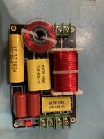
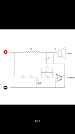
Wharfedale Linton 85 crossover upgrade

Hi, I wanted to upgrade the crossovers of a Wharfedale Linton 85th. I was trying to find out what the signal path is before reaching the driver so I found a schematic online and various images. Looking at the schematic it looks like after the signal reaches the tweeter, it goes through R2, C3 and then through L1 for the second time before go back to the circuit's minus. This seems a bit odd and I was wondering if the polarity of the drivers could be displayed incorrectly here. Why would there be components after the drivers? Can someone explain?

1643448066334.jpg.f3718dafcb17df26feb1f0c94ef61183.jpg


Here is an image of the path on the crossover board.

cvv4fe11.jpg
Projects by fanatics, for fanatics
Get answers and advice for everyone wanting to learn the art of audio.
Join the Community
507,483
Members
7,873,682
Messages

Filter

Forum Statistics

Threads
405,555
Messages
7,873,682
Members
507,483
Latest member
kuttisrank