Hello Community,
I hope this message finds you all in good health and high spirits. I'm reaching out to this knowledgeable forum with a humble request for assistance that holds significant importance to me.
I recently registered here, driven by my passion for electronics and music, to embark on a project that's close to my heart: crafting my very own audio amplifier. This journey has been incredibly rewarding so far, but I've reached a point where I could use a helping hand from experienced minds who understand the intricate world of electronics design and PCB layout.
I must admit that the learning curve has posed some challenges, and my autistic traits have added a layer of complexity to this process. I have always hesitated to share my personal journey, as I've encountered instances where discussing my condition led to misunderstanding or undesired pity. But today, I've decided to reach out because I believe there might be individuals here who can empathize with my journey.
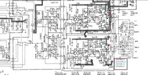
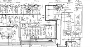
This journey has brought me to the "Apex AX11", a project that struck a deep chord within me due to its intentional omission of a variable resistor and its unique approach to grounding. However, despite my enthusiasm, I've encountered challenges that have left me feeling somewhat stuck. While it's conceivable that the creator of this schematic may be a member of this forum, I remain uncertain about his current level of activity.
In essence, I'm hoping to connect with someone who understands the complexities of dealing with both electronics and autism. Any support and guidance, no matter how small, would be immeasurably valuable to me.
I've dedicated time to studying schematics and electronics, often navigating the journey alone. The process can be incredibly frustrating, especially when the path forward isn't clear. This is where I now find myself, seeking to navigate the realm of components selection, schematics and PCB layout.
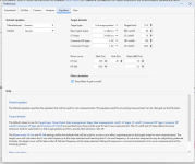
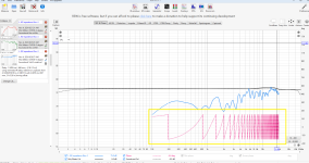
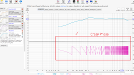
I discovered EasyEDA, a software that breathed new life into my project by offering ready-made component designs. However, my struggle now centers on translating my schematic into a coherent PCB layout. I find that as I move components around, lines appear to shift connections unpredictably. While I understand that components ultimately interconnect, this uncertainty leaves me concerned that I might unintentionally make errors.
In short, I'm reaching out for assistance. Opening up and seeking help is challenging for me, but my intuition tells me that the incredible minds of this forum might hold the solutions I seek. This project means the world to me, and I believe that the understanding and knowledge within this community can help me overcome these obstacles.
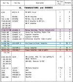
To provide some context about the project, I've made a few component substitutions:
BC546 to BC546ABU
MPSA92 to KSP92BU
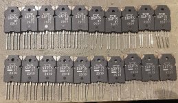
BD249C to TIP35C
BD250C to TIP36C
MPSA13 - Did not find a candidate
I'm seeking your valuable input on whether these component swaps are suitable for the audio amplifier design. Additionally, do you recommend any adjustments to resistor and capacitor values to ensure compatibility and optimal performance?
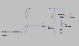
I've also noticed a particular detail within the schematic that has prompted a query. In regard to the speaker (-) input, I've observed an arrow denoted as GND. Could you kindly provide clarification regarding whether the speaker (-) input should be linked to this designated GND arrow? Furthermore, I'm inquisitive about whether the ground stemming from the input should be connected to the left-ground point. Alternatively, is the GND originating from the power supply intended to be connected to the GND point on the right side? Additionally, should both the (+) and (-) speaker inputs be connected to the Output?
I extend my deepest gratitude in advance for any insights, guidance, or assistance you might offer. Your willingness to help me on this journey is a gesture that I deeply appreciate.
Thank you for taking the time to read my message. Your kindness and expertise mean more than words can express.
Warm regards,
Prognosis


