Numerous videos have been posted on YouTube where people describe the impact of discreete opamps in there D-amps like Fosi and Topping etc.
but in the context of Diy amp boards I could not find any reviews.
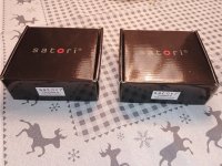
Knowing first hand what a discreete opamp can do in the output stages of two of my DACs, I was excited when Burson Audio approached me to review there V7-C and V7-V in my Class D amp boards.
Many would never consider putting about $170 worth of opamps into a pair of $120 diy Chinese amp modules, but I find it intriguing to see where this can get me sonic wise.
In the next couple of weeks I will put the Burson opamps into three different Class D amp boards and report my personal impressions.
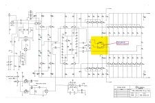
1.TPA 3255
2. Infineon Merus MA12070
3. Infineon Merus MA5332MS
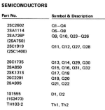
As the latter two got smd based opamps I will supply them with diy adapters.
All this will take a few weeks or even months depending on my work schedule.
In the spirit of diy I will later on also run the discreete opamps with external power as I think that the onboard regulators on most d-amp boards are of poor quality.
My impressions describe the difference between the original opamps and the Burson Audio V7 and are of course subjective and relate to the context of my system and room.
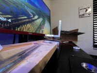
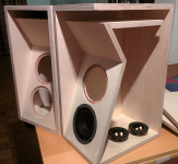
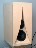
As a source I am using the Wiim Ultra with it's internal dac to keep things simple. The speakers I choose for these reviews are the Quad 21L as they are able to throw an impressive three dimensional sound field if the recording is done well. A deep soundstage is IMO exactly what most stock d-amps are lacking compared to good class A or AB amps.
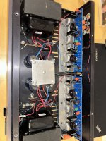
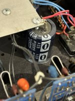
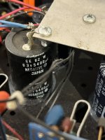
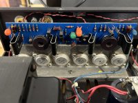
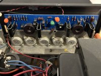
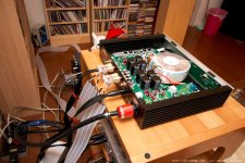
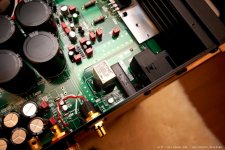
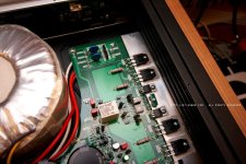
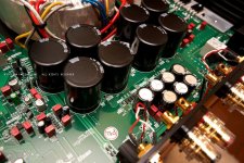
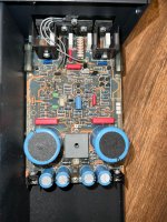
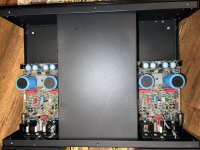
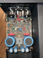
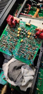
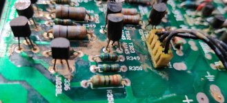
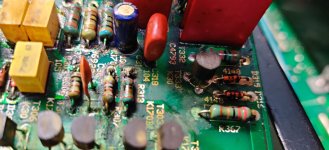
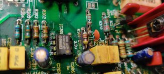
Now on to our first unit the Zero Zone TPA 3255 boards. As we diyers know these Chinese amp boards are seldom equipped with genuine passive or even active components. I made it my habit to change all caps including coupling caps but in the case of the Zero Zone boards I cept them stock for the review.
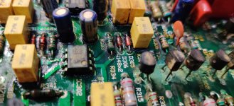
From the first note on after the change to the Burson Audio V7C there was no doubt that the boards reached a new level of performance.
The bass has more authority and control. Nuances come through that I previously did not hear as clearly defined. Also bass drum hits while having more impact are not as overpowering as with the stock opamps.
Instruments in general sound more real and live like.
They are also more carved out and there is more room between them. For the first time I hear adequate depth information on a TPA3255 based board. Not as deep as with my AKSA or EL84 tube amp but to the point that I could hear different planes on well recorded material. Another positive change is how much better cymbals sound. No it's not like you are there but much closer to the real thing than with the stock opamps.
Now to the last observation that in my book is very important: Dynamics. Not being able to play my horn setup at the moment I really appreciate any gains in dynamics. Boy this is the most obvious change to the stock opamps. Everything comes alive big time. Sudden orchestral fortissimos are a joy and mabe this ability to effortlessly deliver dynamic swings is the secret why cymbals sound more real now.
In the past I have done lots of things to get class d amps to sound more real: Transformer coupling, Skipping the whole opamp stage, better coupling caps ect. These Burson discreete opamps transformed my TPA3255 amps like nothing before.
It's to bad I had to do this review in single ended mode as that's the only mode the Wiim Ultras internal dac supports. All the d amps I tested perform much better when driven fully balanced. Most Chinese d amp boards are only pseudo balanced designs and that's why I normally skipped the whole opamp stage.
Fortunately the Zero Zone boards are fully balanced if you bridge two pads.
I will report back on how the Zero Zone boards perform fully balanced once I get my external r2r dac board converted to differencial operation.
Also I still have not tested the V7 vivid in the Zero Zone boards but will report the difference between them and the V7 classic later.
Take care,
Klaus


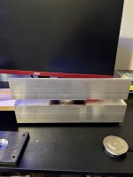
 wish me luck in advance. The only thing missing are tin snips and some long bolts and nuts to secure the SIT-Sandwich in place.
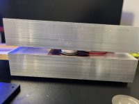


