Hello DIY friends,
As you may or may not be aware. I recently acquired a pair of Tokin 2SK183 from Ebay.
I have searched everything that I can get my hands on regarding these transistors from this site or on the web.
As far as I am aware the only other design using the 2SK183 I have seen on the web is from this website (http://www.ne.jp/asahi/evo/amp/2sk183cspp/rep.htm).
I have no plans to follow that design, except to copy how the designer managed to build a contraption for the Source and the Drain, as I posted here and here.
He used a thick Square piece of Aluminum, I plan on using the L-brackets instead. I am rather worried a bit about heat dissipation, for obvious reasons. If anything I may have to create a proper babysitter for this amp.
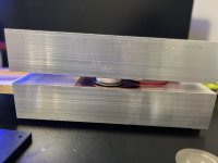
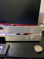
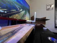
The plan is to create a SIT Sandwich. The Drain and the source are attached to 1mm copper plates, which are then attached to an Aluminum L-Bracket I purchased from Amazon. The Aluminum brackets is then attached to the heatsinks.
The hope is after I finish my SIT sandwich, then I can ship it to a member and he can do some curve tracing for me.
After that, I need to choose a design. Off the top of my head, I prefer to keep this project simple. Either a lightbulb amp (common Source or Drain) or a choke-loaded follower. I have a set of Warbler PCB's that I got from @schultzsch , I am unsure if that will work/be problematic.
Of course, even before I get to that point, I need to have the SITs tested and identify operating points, bias, etc.
I was going to purchase the aluminum and copper plates from onlinemetals.com but right before I was about to purchase, Onlinemetals decided to increase the price of the shipping, which to me was not worth it. So I got the L-Brackets, Copper Plates, and Keratherm thermal pads straight from Bezos Bookstore.
Is there a high chance that I will make a fool out of myself?
Are the 2SK180 and THF51S easier to work with and have already proven designs on this site?
 wish me luck in advance. The only thing missing are tin snips and some long bolts and nuts to secure the SIT-Sandwich in place.
Some porn below....
Best,
Jose
As you may or may not be aware. I recently acquired a pair of Tokin 2SK183 from Ebay.
I have searched everything that I can get my hands on regarding these transistors from this site or on the web.
As far as I am aware the only other design using the 2SK183 I have seen on the web is from this website (http://www.ne.jp/asahi/evo/amp/2sk183cspp/rep.htm).
I have no plans to follow that design, except to copy how the designer managed to build a contraption for the Source and the Drain, as I posted here and here.
He used a thick Square piece of Aluminum, I plan on using the L-brackets instead. I am rather worried a bit about heat dissipation, for obvious reasons. If anything I may have to create a proper babysitter for this amp.
The plan is to create a SIT Sandwich. The Drain and the source are attached to 1mm copper plates, which are then attached to an Aluminum L-Bracket I purchased from Amazon. The Aluminum brackets is then attached to the heatsinks.
The hope is after I finish my SIT sandwich, then I can ship it to a member and he can do some curve tracing for me.
After that, I need to choose a design. Off the top of my head, I prefer to keep this project simple. Either a lightbulb amp (common Source or Drain) or a choke-loaded follower. I have a set of Warbler PCB's that I got from @schultzsch , I am unsure if that will work/be problematic.
Of course, even before I get to that point, I need to have the SITs tested and identify operating points, bias, etc.
I was going to purchase the aluminum and copper plates from onlinemetals.com but right before I was about to purchase, Onlinemetals decided to increase the price of the shipping, which to me was not worth it. So I got the L-Brackets, Copper Plates, and Keratherm thermal pads straight from Bezos Bookstore.
Is there a high chance that I will make a fool out of myself?

Are the 2SK180 and THF51S easier to work with and have already proven designs on this site?

 wish me luck in advance. The only thing missing are tin snips and some long bolts and nuts to secure the SIT-Sandwich in place.
Some porn below....
Best,
Jose
Attachments
Last edited:
Nice set of vfets you got there. Once you find a good way to hold them down and throw away the heat you are good to go.
The ps pcbs that you got will handle 30vdc on the input so don’t go above that.
For the first tests of the circuit you could use the puck mosfet with the gate protector diode connected accordingly, after confirming the bias is working properly you can reverse the diode and mount the big guy.
What you need to do is to reverse the gate protection diode of the vfet, the contrary as it is for when you go with mosfets.I am unsure if that will work/be problematic.
The ps pcbs that you got will handle 30vdc on the input so don’t go above that.
For the first tests of the circuit you could use the puck mosfet with the gate protector diode connected accordingly, after confirming the bias is working properly you can reverse the diode and mount the big guy.
I think I understand what you mean. I believe I have seen ZM do that when switching between MOS and SITS.... I think XA252 or elsewhere.What you need to do is to reverse the gate protection diode of the vfet, the contrary as it is for when you go with mosfets.
The Amy Alice PCB? TBH, I am a dodo with that!The ps pcbs that you got will handle 30vdc on the input so don’t go above that.

I am cheap, so I think I may decide to use a Microwave MOT just to see what it sounds before I commit large bucks for something like the Hammond 193v.
Anyway, I may be getting a little bit ahead of myself. Will keep you posted!
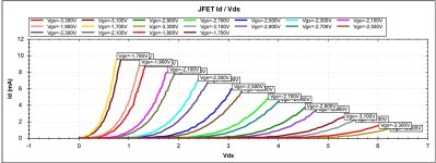
Nice! I'd be happy to run your sandwiches on my tracer.The hope is after I finish my SIT sandwich, then I can ship it to a member and he can do some curve tracing for me.
I like choke loading because it works as a CCS load in the AC/audio domain but does not produce a lot of heat for DC biasing. That's why I went with chokes in the SuSy T. PuckFo amp.After that, I need to choose a design. Off the top of my head, I prefer to keep this project simple. Either a lightbulb amp (common Source or Drain) or a choke-loaded follower.
I like to get this stuff done at local workshops. My own workshop is not exactly well equipped with proper metal working tools, and the workshop guys are usually much better at doing this kind of work. Oh, they often also have some surplus metal pieces which can be used for what I need.I was going to purchase the aluminum and copper plates from onlinemetals.com but right before I was about to purchase, Onlinemetals decided to increase the price of the shipping, which to me was not worth it. So I got the L-Brackets, Copper Plates, and Keratherm thermal pads straight from Bezos Bookstore.
Your approach makes sense to me and there is a lot of potential for good things to happen with this!Is there a high chance that I will make a fool out of myself?
There are a bunch of designs using the 180/182 and 51 here on diyAudio and elsewhere. I guess they are easier to work with because they don't need a sandwich -- but it looks like you've got the SIT-wich figured out.Are the 2SK180 and THF51S easier to work with and have already proven designs on this site?
...
Some porn below....
How sure are you that your 183 parts are legit?[/QUOTE]
Practically everywhere you replace a device that has a positive gate bias voltage(mosfet) with a negative one(sit)I think XA252 or elsewhere.
Yes, A2Cmx-V, it has a dcdc onboard that generates the negative rail. This has a max input vdc of 36v so from here the limit for the max voltage on the input. If you didn’t order the parts until now this dcdc became obsolete and we will need to search for a replacement.The Amy Alice PCB?
When starting to order the parts just let me know what is out of stock and I will search for replacements.
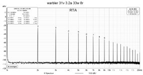
I listened to the Warbler on low impedance and low spl speakers but also on high spl and high impedance ones. It’s a nice sounding amp.
Attachments
Choke loaded followers seem to be all the rage these days!I like choke loading because it works as a CCS load in the AC/audio domain but does not produce a lot of heat for DC biasing. That's why I went with chokes in the SuSy T. PuckFo amp.

In all seriousness I kind of understand the concept of using the choke as the loud. I believe it also gives you some leeway on the rails, meaning that it allows for swinging higher voltage because of the inductance. Drawbacks is bandwidth, and they can be heavy as hell.
I also think so. My comment is more being lighthearted/ sarcastic. I genuinely like playing with amplifiers. This is all just for fun for me.Your approach makes sense to me and there is a lot of potential for good things to happen with this!
in the sit thread I did some cursory measurements of the length, width, and height. I need to get some calipers to do some precise measurements. My only current concern is that I believe there is a thyristor with the same package and name.How sure are you that your 183 parts are legit?
Either way, in order to properly test I still need the Sandwich. Hopefully I can rig a small test just to verify that it is a SIT, before the Ebay refund expires, then I can get the sandwich curve traced.
perfect. I’ll let you know!If you didn’t order the parts until now this dcdc became obsolete and we will need to search for a replacement.
When starting to order the parts just let me know what is out of stock and I will search for replacements.
Oh yeah. Certainly my wife and daughter will yell at me to turn it down! Are you using the RME for the FFT/THD measurements?I listened to the Warbler on low impedance and low spl speakers but also on high spl and high impedance ones. It’s a nice sounding amp.
Iirc there is the pro version which does that much better than the focusrite. Until now the only time when the focusrite wasn’t enough was when I tried to measure the low thd version of the PoP.
You could do some tests at low power to prevent overheating without the sandwich. With a bit of luck thats enough to check for the SIT behaviour of your parts.Hopefully I can rig a small test just to verify that it is a SIT, before the Ebay refund expires, then I can get the sandwich curve traced.
If you have two adjustable bench PSUs (one for drain-source voltage+current, one for gate-source voltage) you could do some rough curve tracing using pen and paper. Just keep a finger on the SK183 to check the heat.
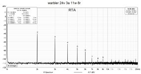
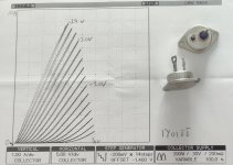
Un few years ago I bought two THF-51s selected with the Id/Vds. This is a graph from a Tokin. The other graph is almost identica. With an PEAK DCA75 the two SITs have this Id/Vds. Only 10mA and 7V.
Attachments
Choke loaded followers seem to be all the rage these days!
not for me Bubba!
That's so predictive and trouble-free path .........

anyhow, after initial solving of mechanicals, take care of driving that gate with big Cojones - meaning proper follower with decent Iq
if you care to share ebay source for these, feel free to send me a PM
I like those but a bit expensive for me right now.With an PEAK DCA75 the two SITs have this Id/Vds. Only 10mA and 7V.
I have one bench supply, guess its time to trace the lines the hard way!

Technical challenges are fun when you are technically proficient, me on the other hand… technically non-proficient at the moment.not for me Bubba!
That's so predictive and trouble-free path .........

take care of driving that gate with big Cojones
Already ordered zm… already ordered! Prudent to skip the lime.


If you are interested, wait until I test them to verify they are the genuine article.
Best,
Jose
Sounds fishy!  I kid of course. I thought about that, but I am trying to use what I have available.
 I kid of course. I thought about that, but I am trying to use what I have available.
Hey folks,
I haven't forgotten about this project. I have all of the parts required, except I'm not sure if I have the correct thermal grease between the SIT and the copper plates. I currently have Corsair TM30 Performance thermal paste in hand. Would that work?
Best,
Jose
I haven't forgotten about this project. I have all of the parts required, except I'm not sure if I have the correct thermal grease between the SIT and the copper plates. I currently have Corsair TM30 Performance thermal paste in hand. Would that work?
Best,
Jose
- Home
- Amplifiers
- Pass Labs
- 2SK183 SIT-WICH
