MarkAudio Alpair 11MS

Hello!


A little question about the MarkAudio Alpair 11MS.

I see on their website there is a ‘big’ dip (see screenshot) around 400Hz.
Can this (maybe) be a ‘measurement-artifact’ or can I 100% expect this same dip when I buy this driver and build it in a cabinet?
Do people here have some experiences with this driver and the dip?

Reseason for asking. I have (due to roommodes) a big dip around 245Hz, and with a big dip around 400Hz this created (I think) a fairly big dip in an important mids-erea.
Not ideal!


Thank you! 🙏🏻

Attachments

  • IMG_7787.jpeg
    IMG_7787.jpeg
    134 KB · Views: 79

Build a conventional 2 way speaker

Hi all. An acquaintance procured some Dynaudio car woofers and is obsessed with building conventional 2 ways with them. I am looking for the flow chart to help begin this journey. I am currently recovering from back surgery and I have to find my t/s parameters but i honestly have no starting point. does anyone have a thought flow process in achieving this goal? Thanks in advance

Garage clean up

Dears,
After years of hoarding I am left with no space in my garage to install work bench for router and other messier construction works. So many things for which to use I would need several human lifes, so time to get rid of it.
It would be my great joy to pass bulkier items, but than again I know these are most difficult (and costly) to pack and ship, so please cherry pick what you need. I really hope that this stuff will be up-cycled and continue life.
Nothing what I will list is fake, components and parts are really old.
In second post I will make one "please read first " note.

Question about crossover design

I have a question for someone smarter than myself(everyone) ; )
I have a few Dunlavy SC-1's and plenty replacement drivers for each.
I have recently purchased a few Scanspeak 25W/8565-00 10"drivers and have been considering building cabinets to house a 10" woofer above and below an SC-1 to make it similar to an SC IVa , Or as I already own a Dunlavy built HRCC crossover (driver matching aside) Build an HRCC center channel and I have enough Scanspeak 10" woofers left to build a pair of "pseudo" Dunlavy Alethas, They are similar to an SC-IVa
The difference is an Aletha has a single 10" woofer firing down and a SC-IVa has 2 10" woofers firing forward.
My general question is: would doubling my inductor value and cutting resistor values in half get me in the ballpark of using just 1 woofer instead of two?
I could possibly drive the woofers separately and do my crossovers on the input of the amp.

I know most people are sick of hearing about people attempting to clone Dunlavy speakers due to the fact that the drivers were heavily QC'ed then matched, hand tuned crossovers then again dialed in inside anechoic chamber, but I think I can atleast get close enough for ME.

Thank you for your time
Johnny

8" 2-way conversion

Hi DiYers,

After a couple of false starts, I'm trying again to do my first custom multi-way DiY project (so far, I've built one set of markaudio full range floorstanders). I have a pair or Mission 770 'Freedom' speakers and one of the woofers is bust. So, I thought it would be fun to use the cabinets to build a new and improved speaker! The cabinets are suited to a 8" + 1" 2-way setup. (Mounting holes are 188mm and 75mm diameter respectively.) The net internal volume of the cabinets (having subtracted the volume of internal bracing/reinforcements) is 33.37 litres. The diameter of the hole in the baffle for a port is 63mm.

I have been searching for a "proven" design which I could briefly simulate in unibox and then recreate for myself. But I can't find anything appropriate where the drivers are available! So, before I give up, my question is: do you know any "proven"/tested designs which might work for a cabinet like this?

My constraints/preferences are:
  • I'm on a bit of a budget (ideally don't want to be spending more than £200-300, but can stretch if that's unrealistic)
  • Wanting to minimise structural modifications to the cabinets – I don't mind expanding the port/driver holes a little to make components fit, but I'd like to keep that kind of thing to a minimum
  • I listen to a broad variety of music: folk, techno, modern classical, pop, AOR, you name it. So I'd like a versatile speaker.
  • My "listening room" (bedroom) is untreated and, given the precarity of the private rental market in London, that's not going to change any time soon. So I don't want an excessively "fussy" speaker, if that makes sense. Relatedly, I don't always listen from the same part of the room. In fact, I like to listen from all over the room – at my desk, on my bed, walking around, etc. To have a sweet spot is great, but I suppose a super directional speaker wouldn't be the best idea.
  • Bass extension is important to me
  • I'm not necessarily interested in the flattest frequency response. I want a speaker that's fun to listen to (which might, for example, mean slightly exaggerated lows/highs?!). When I've listened to great speakers in the past, I've appreciated deep bass response, detail/clarity, and expansive stereo fields.
  • The point, I guess, is that I'm not an audiophile per se, but a music lover and DiY enthusiast undoubtedly.

Although I'm on a budget, I know these things don't always come for free. If there are good speaker kits for me to look at, I'd be open to going down that route. But the idea of copying a more DiY design, putting a crossover together, etc., is more appealing to me.

Thank you in advance for any help you're able to offer!

Lewis

Schematic to LTSPICE questions

Hi everyone! I'm a bit bored at the moment since I don't have anything broken to repair, so I'm playing around with LTSpice. I have two questions, and I'd be grateful if someone could help me out.

1. I have been trying to replicate the left preamp channel of my vintage receiver (a Sony STR-6045) and I am not successful at getting the voltages showed on the schematic. The preamp is called "Equalizer Amplifier Section" in the attached schematic. I'm attaching the ltspice file here.

In my LTSpice file, I have also added a 1Khz source of about 0.25 Volt RMS from the auxiliary jack.

Capture d’écran du 2024-11-02 17-42-49.png


2. I have been reading the excellent tutorials from Mooly and particularily this post: https://www.diyaudio.com/community/...from-beginner-to-advanced.260627/post-4047521. I wanted to a add a model for a replacement transistor that I used before (a KSC1845). In the tutorial, it shows that when the model is used, the information is updated when right-clicking on the transistor. On my simulation, most of the info is empty. I'm doubting it is used. What I am doing wrong?

Capture d’écran du 2024-11-02 17-37-40.png


Nothing is critical here, this is just for personal learning but as always, I big thanks to anybody who can provide solutions or suggestions.

Attachments

How to run TINA-TI on your Mac - for free!

I'm pretty stoked. I have found a way of running Windows applications, including TINA-TI, on my MacBook Pro with the Apple M2 silicon. That seems to be a pretty common desire, so I thought I'd put a guide together on how to make that work.

I have used vmWare Fusion in the past and really liked it, so that was my first go-to. Unfortunately on the M2, Fusion installs the ARM version of Windows 11. That seems to run really well, but for some bizarre reason TINA-TI won't run on Windows 11 ARM. So I decided to give Wine a go instead. That worked! The image below shows TINA-TI running on Mac.
Tina-TI on Mac M2.jpg


Here's the process:
  1. Download Wineskin Winery from Github: https://github.com/Gcenx/WineskinServer?tab=readme-ov-file
  2. Double-click the downloaded file to extract it and double-click the extracted app to start the Winery.
  3. Install a Wineskin engine. I went with the WS11WineCX64Bit23.7.1_D3DMetal-v1.1 engine.
  4. Create an empty .app wrapper. This takes about a minute.
  5. Download or locate the Windows software you would like to install.
  6. Double-click the empty .app wrapper to launch the installation process. Click Install Software and then Choose Setup Executable.
  7. Point the file browser to the installer file for the Windows program that you wish to install. Click Choose.
  8. Then install the program as you would under Windows. You'll have to grant permission to access the Desktop, Documents, and Downloads folders. That's normal.
  9. <tada.wav> You now have a Mac app that contains your Windows program. You'll find the root directory of your Mac mounted as Z:\. If you need to access network or USB drives, mount them on the Mac as normal and browse to Z:\Volumes within the Windows app.
Enjoy.

If you need a bit more step-by-step guidance, including screen shots along the way, please find my writeup here: Running Windows Programs on Mac – Neurochrome.

Tom

NAD C275BEE ideas for troubleshooting

This amplifier have problem with right channel amplifier board, left works fine. I have replaced some defective components as shown but now the amp runs for about 10-15second then it blows a few part in the "red" area.

Problem is that i dont have time to measure before it blows again.
Bulb and variac does not help.
My idea is to disconnect something in circuit to eliminate some parts or maybe bypass "turn on board" so i can use variac.
I am thinking that some active component starts to drift in value when it warms up.
I quickly turn on amp and when it goes out of protection i turn it off within a few seconds before it blows up and there is no DC on output and none of the small components are hot in the red area.

I am stubborn and any help is appreciated.

Attachments

  • nad_c275bee.JPG
    nad_c275bee.JPG
    392.7 KB · Views: 125

Tannoy Legacy Arden Tweeter

Hello DIY Forum Community,

I'm seeking some guidance on repairing a burned Tannoy Legacy Arden Tweeters. Could anyone tell me the original impedance and inductance specifications for these tweeters?

Additionally, I am considering rewiring the voice coil. What differences in performance or sound should I expect if I use round wire instead of flat wire for this purpose? Also, where can I buy flat wire for this application?

I also have an idea to replace the plastic waveguide with one of the same measurements made from copper. Any suggestions on this modification? Will it give any benefits in reproducing high frequencies?

I appreciate any insights or advice you can provide.

IMG_2869.jpeg

E-MU 0404 USB 2.0 and some "artifacts peaks" on left channel

Hi,
I hope so to submit to the right discussion.

I use the emu like a measurement tool for measure dac's, amps e.t.c

I have a problem with the noise on left channel of my emu 0404.
There are always some "artifacts of peaks" at 8KHz, 10KHz, 12KHz and so on.
The right channel is without problem.

Because my english is not good, I have attached an ARTA noise measuring capture with external loopback (analogue line out -> line in), but the same happens and without any connection, only FFT record of noise.

I have seen the same behaviour and to another used emu 0404 usb at the same left channel with the same peaks!

Any suggestion what is the reason?

attachment.php

Attachments

  • left.jpg
    left.jpg
    100.8 KB · Views: 3,196

Your rating sound quality of compression drivers?

Hi to everyone.
Initially, I found information that the best HF and MF are planar and isodynamic emitters, the best of which are AMT (Heil as a type of emitter), then searching for which of them is the best, I found that Beyma TPL is better than the rest, (excludes RaaL in last octaves) continuing to search I found that some users it is not as good against the best compression drivers, on a beryllium membrane.
I have collected a lot of information on the search, both here and on sites in Google. If anyone is interested, I can throw the contents under the spoiler, what I managed to find, although I am sure most will find it meager and uninteresting.
Therefore, I decided to create a separate topic.
I ask everyone to speak out - your driver rating, and in what frequencies, for example, it is clear that 3 inches have a better response due to less weight, and 4 inches have more power and a lower cutoff frequency, (what are the conditions in general, because for example I found that some people prefer the sound of a driver without a horn) but this is all theory, and what kind of sound is interesting.
  • Like
Reactions: MrKlinky

What's goin' on - with NFS

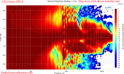
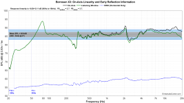
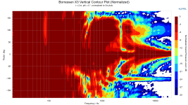
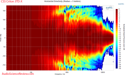
This week appeared two reports of tower speakers, measurements done with Klippel NFS. Both show surpisingly loud response of 800Hz (midrange driver range) vertically at around 110deg which means on top of the tower! Speakers are 3-way with double woofers, but different layout of mid/tweeter. What the heck? Edge diffraction or panel resonance? Or artefact in NFS synthesis?

https://www.audiosciencereview.com/...ds/css-criton-3td-x-kit-speaker-review.58467/
the other is Erin's Audio Corner of Borresen X3 (in Patreon), not yet public.

The CSS has been measured also in anechoic chamber and response is different there, without ripples.
Borresen axial response is smoother at that region.

CSS Criton 3TD-X Tower Floorstanding Kit speaker anechoic frequency response measurement.png CSS Criton 3TD-X Tower Floorstanding Kit speaker horizontal directivity measurement.png CSS Criton 3TD-X Tower Floorstanding Kit speaker vertical directivity measurement.png

Borresen X3 FR_Linearity.png Borresen X3 Horizontal Contour Plot (Normalized).png Borressen X3 Vertical Contour Plot (Normalized).png
  • Like
Reactions: mayhem13

Basic routing question

I recently received some flat packs from Speaker Hardware and overall, they did a very good job.

The main issue is they didn't cut the woofer hole rebates with a big enough diameter, so the woofers will not drop in. Bottom line, I have a widen the rebates a bit. The woofer holes themselves are the correct diameter.

I understand how to do this using a jasper jig, but how do I do it without being able to create the pivot point for the jig?

They also forgot to do the round overs on the enclosure edges, but that is not a problem for me and my less than great routing skills.


woof2.png

Attachments

  • woof.jpg
    woof.jpg
    375.4 KB · Views: 42
  • Like
Reactions: olsond3

Hello i’m Montagna and I will learn so much

Hi I’m from Italy. I read about you and I see that your forum was amazing.
I’m just start now in electric issue but I’m a musicians and in the past I’m the owner of rec/mix/mastering studio. Now it’s the Moment to go deep inside the electronic device for music. I just repair something but i would like grow up maybe with you. Let me know

Sound System for Classroom

Hi, I teach in Thailand and want to upgrade the sound system in the classroom. It's 34'x20'x8', cement walls and windows along two walls. I'd like recommendations for a 6-8 channel system, powered or passive mixer with powered speakers. I show Youtube videos and use two Bluetooth microphones. I want to completely replace all components. Any recommendations please?


classroom-1.jpg
classroom-2.jpg

Isolation transformer & Setting up an electronics workbench Newbie question

Hi, I just got myself a 1:1 transformer and watched several videos suggesting what NOT to do regarding the neutral connection.
Since neutral and earth are joined at the distribution panel it makes sense that the transformer secondary neutral should be isolated from the primary neutral.

Question 1: does the socket on the secondary get a ground connection at all? Or do i just wire Live and neutral to it?

Question 2: if I wanted to have this setup on a separate breaker box, How and where in the circuit would I wire an RCD?
Since it is isolated from mains how is it supposed to measure the residual current leaking to ground if there is no ground?

I understand that one needs to touch both sides of the secondary to get shocked but it still sounds sketchh and potentially dangerous. So is there a way to trip a breaker on the transformer secondary for extra safety?

Help! New guts for vintage speaker... Full range or coaxial? Markaudio? Ideas welcome!

Hello DIY audio. Long time reader, first time poster. Please be kind 🙂

I have a thing for the vintage aesthetic. I love how old gear was made with love, is repairable, has lasted 50 years+, is a form of recycling. Etc etc. That said, although I have experimented happily with many old speakers, its more the amplifiers & receivers that i actually listen to (with newer speakers).

Recently I bought some Sansui SP-25 wooden lattice speakers for £30 all in with one driver open circuit. I deliberately bought them like this in order to update with a nice full range driver, so that i can enjoy the vintage look, while pleasing my ears.

Firstly i have never built any speakers. I am a novice. I do know there will be compromises. The lattice will create reflections, which I can live with, I am more worried about that 27mm baffle lip. Perhaps I can line it with felt?

Driver suggestions please! And any tips or tricks that might lessen the existing boxes shortcomings!!

Please see photos attached for internal / relevant dimensions etc.

I look forward to any help!

Attachments

  • 20241023_123050.jpg
    20241023_123050.jpg
    537.9 KB · Views: 87
  • 20241023_123050.jpg
    20241023_123050.jpg
    537.9 KB · Views: 84
  • 20241023_123110.jpg
    20241023_123110.jpg
    164.5 KB · Views: 80
  • 20241023_123127.jpg
    20241023_123127.jpg
    530.7 KB · Views: 88

Carver SF-10-CW rattling

Hey guys, the sub in my Carver Knight Shadow is making a rattling sound on some frequencies at louder volumes. It even rattles when the sub is being played out of the box. I find no breaks in the cone, spider or cap seal, to my eye. When i push down on the sub, the DC resistance goes to 0. Pushing up it gets a variable reading as I would expect. Is this a sign of a defective driver? The rattle sounds like something is being hit against the cone, getting louder as the volume increases. I would like to inspect inside the dust cap but have no idea how to get the cap off. I encourage your thoughts for remedy.

IMG_4720.jpg

Elekit 8200 loud hum, then blown internal fuse

Hello all
My Elekit 8200 suffered some kind of electrical surge that tripped the breaker on the circuit that it was plugged into. When I turned the amp on all I got was a loud hum in the left speaker, nothing in the right speaker. The tube heaters came on. I turned it off, and then turned it on again. Same loud hum, noticed that the green LED was AMBER now. In about a minute I smelled some heat then it shut off by itself. The internal fuse was blown and resistors #19 and #21 were BURNT!!

Any ideas on how to procced? Is there anyone who can diagnose and fix board?

Thank you -
Bill Tecosky

greetings to all members from Italy!

I'm Francesco and I live in the area near Lake Garda in the province of Brescia, I'm 60 years old and have been retired for a few years and
I cultivate a great passion for high fidelity and dedicate my time to repairing hi-fi equipment and electronic constructions.
I have a fierce inclination towards analog vinyl players with particular attention to the pulley drive system of the platter, mainly of the Lenco brand turntables, for which I have carried out some studies aimed at improving performance with a technical solution regarding the motor electric which is giving good results.
I have a listening system with handcrafted electronic components, assembled without great demands, but still of good quality in terms of sound quality.
the power of the chain is played by the high efficiency acoustic speakers from Lowther placed in the loaded horn cabinets designed by Ian Hedlund, and a dedicated Class A amplifier
I take this opportunity to send greetings to anyone who can read these lines,
a big hug Francesco 🙂
  • Like
Reactions: krivium

Hi from UK

Hello. My name is Andy and I am 49 years old from the UK. I got into tubes about 2016/17 at which point I built a Bottlehead Crack and of course got drawn into the obsession resulting a few months later and with a much lighter wallet a heavily modded Crack and some very nice tubes. I have 2 TS5998 which will hopefully last until I can no longer hear and I have bought some really nice ECC82.

I mean mid range grails, not the uber priced ones. Siemens chrome plate, Marconi (Mullard) 1959 B329, Brimar CV4003 and many more. Most I paid (before this week) for any tube was £33 for the Siemens. I got the TS5998 for £40 the pair so was very lucky. I just broke that record a few days ago and paid £50 for a K61 1959 Halo wavy glass which I am yet to receive. Branded Cossor so yet to be identified in terms of actual factory.

My favourite ECC82 is a Mazda foreign smooth long plate which after some research turned out to be EI Yugoslavia but it makes my ears sing and thats what matters. That one probably cost me less than a tenner. No-one wants the Mazdas.
  • Like
Reactions: Globulator

Help request: DIY 1u 4x WiiM Pro Plus rack + faceplate

Hi - I'm hoping to build a 1u 4x WiiM Pro Plus case for a CI application, but need advice, so my fingers are crossed that I've come to the right place.

Here are the design goals:
  • 1U form factor
  • 4x (8ch) WiiM Pro Plus to match a 1U 8ch CI amp
  • Airplay 2 support (rules out a possible Origin Acoustic CI 4x WiiM that has yet to pass FCC testing)
  • 1 power plug & 1 eth plug to the 1u appliance to minimize rack wiring & save on rack switch port capacity
  • Eth-only streaming - no wifi necessary
This is for a house-wide audio system with the need for 6 of these 4 WiiM devices, saving 6U over a 2 WiiM per 1U setup, which would be a big plus and might mean not having to get a second rack.

Does anyone have any experience with 3d printing custom face plates for rack-mounted solutions or advice on where to go to get a prototype built?

My hope is that we'd just need to replicate the port section of the Standard WiiM backpanel in a 4-wide setup. With a case, the WP+ is 5+ inches, but the PCBs and the backpanel ports are just under 4" wide.

The ultimate setup would be to un-clamshell the WiiM internal PCBs and get 8 WiiMs into a 1U rack setup, as I have no need for WiFi or Analog I/O, so the custom backplate could just expose the bottom half of the WiiM backpanel. Not sure what that would do for heating, though.

1731955623463.png


Thanks in advance for any help / guidance!

  • Poll Poll
Your horn choice for a BMS4590 coaxial compression driver


Hi,

I am planning on building a new pair of speakers for my room. The woofer size will be 12 inch. I am having trouble on deciding if the ZXPC k510 or the ZXPC 18 x 10 horn will be a better choice. The k510 is much cheaper to ship to Europe and is a bit smaller. I wonder if the 18 x 10 horn is worth the extra money and space (wider speaker) for better sound quality.

What horn would be your choice for the BMS 4590 coaxial compression driver and why?

Parasound JC-1 amp failure

I had one of my amps burned up in flames. Major failure with burned traces and shot output transistors. Clouds of smoke with flame coming through the top cover. Scary stuff... Oh well, so is life. This happened back in 2020. Messaged Tony at Parasound and placed the order for new Main and Driver boards. The parts are not obtainable through reputable stores and the cost buying from Parasound wouldn't make it worthwhile effort at the time. When I tried to install the mainboard I realized that the new board is not compatible with the chassis and there is interference with protection board. So I had to replace the bars transistors are mounted to with the old ones. I have used the thermal grease recommended by Tony which I bought at mouser. Fired the amp up, adjusted bias, let it sit for 1 hour monitored bias, all good.
Fired it amp played music for 2 hours and it burned again. This time I was able to pull the power plug pretty quick. Looks like all output transistors are gone (brought 4 probe ohm meter from work), all emitter resistors on SC3264 side are gone. One emitter resistor R72 on the SA1295 side is gone as well. Looks like protection board tried to stop this uncontrolled non-sense until Q2 and R6 were burned in flames and 50V C69 got swollen from excitement seeing the firework show. Some other low power resistors are gone (R24, R137) and it doesn't stop there as there is a problem with the driver board.

Family health issues kept me away for quite some time attention. Now I am back to audio hobby and would like to give this amp a third chance. Wrote to Parasound about a year ago but the ownership has changed. The new quote for both boards was substantially higher. 🙁. Contacted Parasound recently (same email) but no reply. Filed the form online and got reply they don't sell parts. 🙁. A few days ago I noticed they have opened an online store with replamenet boards 🙂 The cost of boards is almost 3x of what I have paid initially... 🙁(( Since I have nothing to loose I would like to try to repair this guy but buying a replacement board at that cost make no sense as I can obtain a used amp for that price (likely cheaper).

The biggest question who is selling the parts for JC1? How closely do they need to be matched?
a) output transistors 2SC3264 and 2SA1295
b) fets: 2SK1530 (Q38) and 2SJ201 (Q37)
c) (Q1) 2SK3421 and (Q30) 2SA3058. Haven't checked them yet...
d) Driver board Q32 IRF610 and Q31 IRF9610
e) Any recommendations for emitter resistors brand and nominal value (metal oxide)? In the schematic they are 0.1Ohm, but I have heard they have switched to 0.15Ohm later on. Strange color code. I forgot what mine measured at (those that are still alive).

Another interesting observation the complementary output pair 2SC3264 and 2SA1295 on the new board I bought in 2020 had the last letter covered with the paint on all transistors. On my working amp with the old board I have 2SA1295 95Y and 2SC3264 5NY. I removed the paint on the transistors on my "new" main board and saw 2SA1295 65O and 2SC3264 64O (and 65O). Not sure if I understand this correctly, but O vs Y is hfe rank per datasheet. Does it even matter? I think it does since they were covered with paint 🙂 https://www.semicon.sanken-ele.co.jp/sk_content/2sa1295_ds_en.pdf

Please help or tell me to forget about it...

Long time lurker....

Hi, I've been lurking for a while picking up all sorts of bits of amazing information - this place is how the web should be (and sadly, it's how many more bits of it used to be!)

I'm in the process of making the "DIY 4 Phase Sinewave Generator for Turntable Motor Drive" ... though that one keeps getting put on the back boiler as life gets in the way. Will put the finishing touches to it soon.

Nyquist theorem and noise measurement

Good morning,
I would like to make a noise measurement using a soundcard with adequate sampling at a good spectral resolution.
Speaking with a radio amateur I was told that according to the Nyquist theorem if e.g. I want to make a measurement on a 50KHz bandwidth, I need at least 96KHz set, i.e. double the sampling frequency, to have a reliable result.
Now maybe mine is a stupid question from a new expert in signal theory, but if the BW of my amplifier on which I carry out measurements was 70KHz, how should I behave in this regard. Should I filter further down to 50KHz or below?
This is because for the calculation of nV/√Hz of interest to me, the frequency response is involved (with a correction factor perhaps if there is no "brick wall").

However, having fiddled around a bit, I have already seen for myself that common soundcards above 20-24KHz then tend to go down a step, due to an LP filter of the DAC, and so on until the end of the bandwidth.
So I wonder if it still makes sense to sample above 20KHz (even if feasible) if the measurement essentially doesn't change much.

Thank you

Faulty Tweeter or Crossover (PMC TB2+)

One of my speakers is showing a big dip in the high frequency range. I initially though that it would be a failing crossover capicitor. I had a look at the crossover and it seems quite simple, with one film 3Mfd cap (a Bennic XPP polypropylene film, I assume the highpass tweeter) and one 20MFD electrolytic (an Alcap electrolytic). I understand that polypropylene caps rarely fail, and I thought tweeters generally either worked or they didn't.

Does anyone have any ideas?

These sweeps were taken independently by the way.
SpeakerDip.png

Hello!

Hello everyone,
I am an Italian diyer with a passion for music, cinema, electronics (mainly Audio) and cooking,
just to name the main ones.
Unfortunately I am really expert only in the last one.
I hope to learn many things and maybe teach some, and with a bit of luck, build things that work (well).

Greatings,
Marco

Using Fender Deluxe Transformer in a 5F1 Champ—Concerns with High B+ on 5Y3GT Rectifier

I'm building a Fender Champ 5F1 but only have a 290BBX Deluxe transformer on hand, which has a higher B+ than the typical 5F1 transformer. I know this will raise the plate voltage across the circuit, and I’m curious about the impact on the rectifier tube, especially since the 5F1 is Class A and runs the 6V6 at high continuous current.

Will the higher B+ voltage from the Deluxe transformer place excessive strain on the 5Y3GT rectifier, potentially shortening its lifespan or causing overheating due to continuous high current in Class A operation? I’m open to adding resistors after the rectifier to bring down the voltage for the rest of the circuit, but I’d like to understand if this would adequately protect the 5Y3GT. Any advice or experience with similar setups would be appreciated!

EVA foam for performance speaker enclosures

I was very inspired by xrk971's thread Foam Core Board Speaker Enclosures? - diyAudio

When that thread started it was aiming at low cost, rapid building as the motivation for using foam. But it occurred to me that the right foam might actually be a better building material than wood for speaker enclosure. Wood is inherently a resonant material; it is used for musical instruments because of it resonant nature. Foam on the other hand is often used for soundproofing. Hit a piece of wood and it makes a medium to high pitched resonant sound. Hit a piece of foam and it sounds dead. As wood get denser, the sound it makes rises in pitch.

The Celestion SL600 and 6000 speakers from the 1980's also used a very different thinking for the enclosure. These speakers used a lightweight aluminum honeycomb material called aerolam.
Celestion System 6000 loudspeaker system | Stereophile.com[/FONT]
Celestion SL600si loudspeaker & DLP600 digital equalizer | Stereophile.com
And quoting from that article

The cabinet is unique to the SL600Si (and similar to the SL700) in being fabricated from a 0.5"-thick, metal-honeycomb aircraft flooring material. While low in mass, thus minimizing energy storage, it is sufficiently stiff enough for the resonances of its panels to be pushed almost two octaves higher in frequency than with a conventional wooden cabinet. The contribution to the overall sound from the flexing of the enclosure walls will thus be moved away from the region where instruments and voices have their energy maxima, and will also be lower in level. The result should be a low delayed-resonance signature, with correspondingly low levels of midrange coloration. Because the walls of the enclosure will now be virtually transparent to midrange sound, it is filled with carefully graded foam to absorb as much of the woofer's backwave as possible.
I always thought that celestion was onto something here with: low mass, low energy storage, and shifting the wall resonance away from the midrange.

Also when we build speaker enclosures out of wood, we have to line the walls to damp reflections, and fill the box to absorb the sound (make it non-transparent), and we have to add bracing and mass to the wood walls to damp resonance and vibrations. We have to apply all of these technique to compensate for the fact that wood is a resonant material with a pitch often in the middle-to-high-band frequencies.

As I looked around at different foams I realized that the ideal speaker enclosure material might be
- low mass
- semi-ridging / semi-flexible to have a low resonance frequency
- low energy storage
- sound absorbing (non-reflective)
- vibration absorbing
- and with a low resonant frequency (since a perfect sound absorber does not exist)

I found a foam called EVA which appears to have all these properties.
EVA Foam | popular Closed Cell Foam
intecfoams UK EVA
  • Impact and vibration absorption
  • Acoustic and thermal insulation properties
  • Buoyancy with low water absorption
  • Suitability for thermo-forming and thermo-moulding
EVA is also very easy to work with. It is one of the main materials used in costume building because of it's easy workability. Exacto knifes, glues, and heat guns allow for easy shaping into any form (curves, domes, facets...)
Creating a Costume/Cosplay from E.V.A Foam : EVA Foam & The Differnt Types Youll Use.
And EVA can be wet or dry sanded to create smooth surfaces, bevels, waveguides..
EVA foam also laminates very well to create thick panels. And I believe that the laminated EVA, with the multiple boundary layers, may have additional benefits.

I am posting this in the fullrange section because I think the fullrange crowd is open minded to experimentation, but I believe from my builds so far that EVA foam works just as well in multi-way designs.

I have two builds currently using EVA foam. A full-range sealed box with an FF105wk driver, and a 2way high-end build using a Satori MW16 and RS28f tweeter with a custom shaped waveguide and an LR2 crossover. I will be posting more details about these builds and my building techniques.

Some preliminary panel property testing. I will explore this more in the future once I can build a better testing apparatus.
Panel resonance tests:
http://www.diyaudio.com/forums/full...rmance-speaker-enclosures-16.html#post4456901

Panel transmission tests:
http://www.diyaudio.com/forums/full...rmance-speaker-enclosures-24.html#post4467017

Mattes flower speakers : OB fullrange using high density EVA foam for flower shaped baffles (shared by user Mattes, Oct 2018)
full range flower
with the 18" bass flower
My first flower petals experiment


I also started a thread on my multi-way experiments with EVA foam speakers over here OB compact 3way nearfield monitor
Hello from Oklahoma

Hello from Edmond, OK. I joined this forum because I have a Klipsch R-112SW that has developed the dreaded thumping sound. I am interested in finding someone that can repair whatever is wrong with amplifier/power supply. I have removed the panel from the subwoofer and conducted a visual inspection of the circuit boards. I do not see anything immediately obvious such as burned resistors or bulging capacitors. Any help would be great appreciated.

I spent 31 years in the Nuclear Navy in the submarine community. I started out in subs as an Electrician's Mate and later became an officer. I am now fully retired and no longer have the desire to tinker around with things like repairing circuit boards.

Thanks, Jim

The device that sums the signals, what does it called?

I'm searching for a device that could sum two signals together. Those signals are the outputs from the active crossover, high and low frequencies signals. I'd like to mix them together again after filtered. The purpose is because I still want the full-range signal but just want to adjust the levels of low and high frequencies independently. For example, the crossover point is set at 85Hz, above and below 85Hz will be independently adjusted levels.

1) What does the device that do this task called? a mixer, multiplexer, etc.?
2) Is it the same thing as the "stereo to mono audio converter"?

Ray Media RMC RL- s881. For McIntosh MCD201 CD player not working i want help about to find this

Hi, i have McIntosh mcd-201 cd player, my issue is i can't find his mechanism i have new laser lens. But can't find hole mechanism even not find in Google and nothing in replacement for Raymedia RMC RL-s881, please help about replacement or same mechanism finding...
IMG_20240213_233359336_HDR.jpg

Attachments

  • IMG_20240213_225254283_HDR.jpg
    IMG_20240213_225254283_HDR.jpg
    307 KB · Views: 218

MosFET gyrator in LTSpice

Hi,

I've put a generic gyrator diagram in LTSpice. This should simulate a choke with 47H and 60 Ohm.

The reason for this is that I want to "see" how much an AC signal on top of the DC is filtered by the gyrator. The input is 600 VDC with 0.5 Volt AC and a load (R4) of 500 mA.
I would like to use the probe in LTSpice to check all points of the diagram for voltages, currents, etc., but when I click RUN I get a list with parameters.
There is no parameter for the output AC voltage in this parameter list, so I still cannot check if it works.

I attach my .asc file and I hope someone with better LTSpice knowledge can make the proper adjustments to get this running.

Regards, Gerrit

Attachments

Starting my study on horns for compression drivers

good morning a friend of mine wants to set up a small disco in his basement
He knows even less than me about hifi but he would like a speaker with a horn on the mid-highs and he asked me to study the horns
I have a really strange question but I have to ask it
I have identified three main elements in a horn Horn, magnet and diaphragm
In my opinion in order of impact on the sound the horn comes first then the diaphragm and finally the magnet
Am I right?
Another question What would be the best xover frequency for a 2 ways speaker with a 10" woofer ?
i see commercial speakers crossed very high at 5kHz Is it not too high ? is it the best choice ?
thank you very much

Advice on bracing for travelers by Holtz and Campbell

Screenshot 2024-11-09 171726.png

What would be the best way to go on about this? In the illustration its 1 inch from the sides even though it says 2 in the document ( I think the illustrations are reused from the finalists which are a similar speaker)? I'm a bit lost on it since that would significantly reduce the cutout area. the dimensions of the brace are 24cm x 34cm. the effective dimensions are 24cm x 30cm since lengthwise 4cm is sitting directly under mid driver tunnel bracing. What do you think about going with an ellipse or circle cutouts with the same surface of the illustrated? Should I just do 2 inches on the sides and leave the middle without any additional bracing? Or just do the window thing?

Op-amp (or any feedback amplifier) stability and source impedance

Hi all,

On the thread https://www.diyaudio.com/community/...citor-for-a-fet-input-amp.419886/post-7843781 there was an off-topic discussion about source impedance and op-amp stability. It is obvious to me that for an amplifier with series feedback at the input and shunt feedback at the output, a too high source impedance with the wrong phase has the same kind of impact as too low load impedance with the wrong phase, because they are in the loop gain equation in a similar way, but apparently everyone else disagrees. In order not to contaminate the other thread too much, I start this one.

Attached is an explanation of my point of view, which was also posted in the other thread. As I wrote it in the middle of the night and wanted to get some sleep, I took a couple of shortcuts. I'll try to fix that over the next couple of days.

The replies to it were:


Best regards,
Marcel

Edit: the latest and hopefully greatest version of the report is here: https://www.diyaudio.com/community/attachments/sourceimpedance-pdf.1382244/

Attachments

  • Like
Reactions: Masca64

  • Locked
Single Ended, 40 VDC, 2 A, TO-220

More as an encouragement, and also to push the common imaginary boundaries in terms of parts and sound...

Roughly ahead:
A TO-220 generally sounds "better" than a TO-247. Cross-sections and shape are the main cause. The power and load specifications seem to discourage many audio enthusiasts from putting high loads on TO-220s. But don't worry: as always, first try;-)
It is also important to avoid connecting parts in parallel, as this leads to rounding and blurring of the sound. In addition, the practical layout of a paralleling is not considered by the vast majority, which in turn worsens the sound.

Here are two Single Ended to see: a BD711 (officially 75 watts and 12 A), a TO-220 power resistor and a trimmer each, at 35 VDC and > 2 amps. One input and one output capacitor. Nothing else. Sounds great;-) Although these BD711 are not audio suitable transistors.
Transformer here > 800 watts. I have a few 150 mF, 35 VDC electrolytic capacitors. A changeover switch with a load resistor is suitable as a switch-on delay. Quite pragmatic;-)
The heat sink is of course somewhat larger, capable of cooling around 300 watts passively and many thousands of watts actively.
It may well be that a water cooling system with radiators as heat sinks is cheaper than the one you see. I think I presented such a system - for such large projects - here almost 20 years ago. If you use anodized aluminium, a mica plate could be omitted. I also have powder-coated heat sinks that make a mica disk unnecessary. Anyone who has ever experienced the difference in heat dissipation...-)
And the sound, the distortion behavior of the heat sinks also modulates the current, i.e. the signal, i.e. the sound. I would advise consideration here.

With such an amplifier (textbooks at the front;-) you can let off steam with parts and their sound. It is worth testing a large number of them to get maximum performance. Because don't forget: every part modulates the signal with its character, which is not indicated in lines and numbers;-)
What always will remain: a clear, clean, contoured, powerful, max. dynamic sound, not feasable with analog pp.

One day I want to try where the load ends, replace the load resistor with a transistor, build the thing balanced, maybe one or the other...
... 2 x TO-126 instead one TO-220;-?
I'll report;-)

But first of all, this thread has been started to encourage.

Attachments

  • DSCN0613.JPG
    DSCN0613.JPG
    532.2 KB · Views: 316

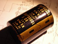
Fake ELNA LAO 10000uf/80V from E-Bay seller

WARNINGS for "sharpseller2000" on E-Bay.
He sends out fake ELNA LAO 10000uF/80V capacitors.
On the picture in the advertisment he shows almost look-like-real ELNA LAO, but when you get it, it is a completely different capacitor!!
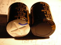
Marking on the fake is ELNA LA5 but color of the sleeve and print is not by ELNA standard.
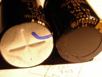
After cutting of the insulation pad on the top, there is a deeply pressed cross on the aluminium can top. Not the ELNA sword like rupture engravings.
(You can also see the marker pen mark, where the new counterfeit sleeve negative should be)

Picture No 1 is what sharpseller shows in his advertisment
Picture No 2-4 is what you get when you buy it
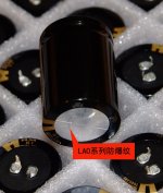
Picture No 5, 6 and 8 is how ELNA LAO should look like.
Picture No 7 is a real ELNA LA5 capacitor in black sleeve with white printing

Price I paid for 10 pcs is USD80. I have had a long discussion with him, but he don't admit they are fakes. Just other Japanese ELNA LAO he says, because his supplier says so.
Even when the fakes he sent have LA5 printed in gold printing on them and have no ELNA can.

The last "offer" I got from him is a USD30 + postage USD32 in refund, if I return the fakes to him!! That means I would lose USD50 and have no capacitors at all!! And I dont belive at all, he will refund anythiong. Just try to stretch out the time so I will miss the opportunity to give him a negative.

"hi there,
refund will be just fine as i always do .
but my supplier is asking products return then i can get my money back. to be honest, i may not be as professional as you are, but i trust my supplier. will find out what is happening later.
before it .should i give you half refund $15 first? and after products return, then refund the another $15 half and the return postage as well.
hope we can solve the issue, don't worry about it.
regards
Harry"


I don"t trust him about anything, have now given him a negative feedback and dont expect any refund.

I also appriciate if other cheated DIY:ers here, share their experiances of other E-Bay sellers in this thread

JohanB

P.S.
Mesurements of the faked caps shows around 8200uF and they withstand 80VDC + 10% without leaking more than 10uA. ESR is around 50mOhm. What I can understand they are of some Nichicon series (because the cross stamp) or other no-brand Chinese manufacture.

Attachments

  • $_57.JPG
    $_57.JPG
    432.5 KB · Views: 2,575
  • FakeElna 002.jpg
    FakeElna 002.jpg
    765.8 KB · Views: 2,514
  • FakeElna 003.jpg
    FakeElna 003.jpg
    826.5 KB · Views: 2,458
  • FakeElna 004.jpg
    FakeElna 004.jpg
    748 KB · Views: 2,393
  • RealElna-3.jpg
    RealElna-3.jpg
    125.3 KB · Views: 2,415
  • RealElna-4.jpg
    RealElna-4.jpg
    11.6 KB · Views: 1,446
  • RealElnaLA5.jpg
    RealElnaLA5.jpg
    89.2 KB · Views: 1,460
  • RealElnaLao.jpg
    RealElnaLao.jpg
    137.1 KB · Views: 1,387

Meanwell gst160a whining and squealing through speakers

Hey everyone,

Please note I’m not an expert and this could be an obvious issue. Please take that into consideration as I’m learning.

So I’m putting together an amp using a wondom jab5 and a mean well gst160a

I know the amp is working because when I use a different power supply (mean well rsp 230 27) it works fine, there is a very faint white noise coming from the speakers but it’s very quiet.

But when I use the gst160a I get slightly louder white noise and if I connect an aux cable I get a horrible electronic squeal.

More info:

The power supply is connected using a kpjx panel mount to a power switch and then to amp.

My amp enclosure is plastic. It’s a 3d printed part.

I’ve also tested it outside of the enclosure with just all the parts loose and far away from each other.

I believe it’s related to the power supply as my other power supply doesn’t have this issue. (Note I don’t want to use the other power supply as it has a noisy fan which drives me mad).

Any ideas would be very helpful.

The jab 5 manual recommends the mean well gst160a so I’m suprised it wasn’t just plug and play.

Thanks so much

Will

DIY Case w/Thick Aluminum Front Panel, Switches, Pots, & Terminals

SOLD

DIY Preamp/Amp/DAC Aluminum Enclosure Case w/Switches, Pots, & Terminals

This is on the 'bay (with lots more pictures), which gives buyer protection and much lower shipping costs; currently no bites at $19 minimum bid.

Find by searching for "Preamp/Amp/DAC Aluminum Enclosure Case w/Switches, Pots, & Terminals"

Black anodized front panel is 17.25 in. wide X 2.4 in. tall X 0.26 in. thick

Internal dimensions are 17 in. wide X 5 7/8 in. deep X 2 in. tall

Height with feet is 2.7 in.

Top and bottom cases are 14 gauge aluminum (0.068 in.)

Already mounted on front panel are:

- 1 ea DPDT (ON-OFF-ON) power switch; see picture for ratings

- 2 ea DPDT (ON-OFF-ON) signal switch

- 2 ea DPDT (ON-ON) signal switch

Already mounted on rear panel are:

- 5 ea red-coded RCA jack

- 5 ea black-coded RCA jack

Also included but not mounted are:

- Illuminated pushbutton power switch (push on/push off)*

- Green pushbutton switch, NO (normally open)

The video shows the cosmetic condition of the front panel; note that at the bottom edge below the middle switch there's a little bit of missing anodize that I touched up with a black felt tip pen.

Also, the left and right edges of the front panel got scraped in storage, so I refinished them with a surface-conditioning wheel and painted them with a marking pen.

* I tested the illuminated switch for function; it lights up (upper and lower termnals), but I'm a bit puzzledby the switching terminals (the three in a horizontal row).

It can be either NO or NC by using the center terminal and one of the edge terminals, but the "on" resistance is 60-ish ohms; not sure what to make of that but I'm not really an electronics guy.

Attachments

  • 1731994644913.png
    1731994644913.png
    628.4 KB · Views: 199

JFETs - how to keep healthy soldering

I am not lucky soldering JFETs and MOSFETs, although I am careful with static electricity and such.

Now I can vaguely remember I read a long time ago FETs were sold with the three leads, gate, drain and source clamped together with a peace of metal to protect it. After soldering the metal was supposed to be removed.

Is that method still advisable?

Any other advise?

Thanks!

Phono preamp from the LT1115 datasheet

Hi all,

I would like to build the phono preamp from the LT1115 datasheet, the schematic shown on the first page of the document. This will be used with a Dynavector 20X-L (.3 mv - moving coil cartridge).

I have a few questions about the circuit:

The 2N4304 FET used to bias the LT1115 output in class A is no longer available, which component could I use to replace it? what about replacing it with a current source diode like the 1N5305 or even using a LM334 adjustable current source.

If I change the FET how can I calculate the value for the resistor in series with it? I can always go by trial and error... 🙂

Which component would be the best option in order to keep the noise level as low as possible.

What is the purpose of the 3n9 capacitor connecting the output to the ground? What about the 25K resistor marked as RL?

There is no coupling capacitor in the output of this circuit, should I add one, or is this not necessary with this topology.

What is the purpose of the 2200uF and 4.7uF (film) caps in parallel that connect part of the feedback loop to the ground?

Can I power this with +12 / -12 instead of 18 volts? what would be the drawbacks? If 12 volts is possible I could try to power it with batteries....

Thank you in advance,
Luis

A Hafler inspired solution for the phantom center image problem

For years I've been pursuing a way of getting better stereo sound like you get when you use a divider wall between stereo speakers to eliminate crosstalk and interference patterns. One way to do this is to add more channels using a matrix. A simple and well known matrix is to turn L and R signals into L-R, L+R, and R-L. What no one has ever told me is that this simple array will do amazing things if you space the speakers apart properly and listen at an appropriate distance. Center panned sounds only play through the center speaker, so there are no interference patterns so that solves the phantom center problem. But what happens when a sound is panned hard to the right or left? For a right panned signal you end up with the array playing a -R in the left channel, a R in the center and another R in the right channel. This of course creates interference patterns, but good ones! They work to create the proper stereo separation and never cause a null to cross our ears! This is because there is a null in the center of the sound field instead of a lobe. So each ear gets an appropriate stereo lobe! Each ear gets a lobe - so punny!

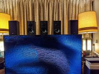
Here's a picture of my current array using basic little Sony SSCS-5 speakers

5SpeakerStereoArray.jpg

You can see I'm actually using 5 speakers here. The center channel plays full range down to 100Hz. The inside left and right play down to 600Hz. The outsides play 600Hz and down. This just helps to boost the stereo effect as the wavelengths start to get long compared to the width of the array. 3 speakers works great. 5 just gives it a little something extra and I happen to have lots of speakers and amp channels available.

Watch this video to see how the interference patterns produce excellent stereo throughout a huge range of frequencies. I used Falstadt's great ripple tank simulator to demonstrate how the effect works over a huge range of frequencies. http://www.falstad.com/ripple/Ripple.html. The three dots at the top of the screen represent an appropriately spaced array of 3 speakers playing a hard right panned signal. The circle down below represents the listener's head with strong signal reaching the right ear and weaker signal that is phase delayed reaching the left ear - as it should be. As I play a wide variety of frequencies you can see that strong stereo separation is maintained and no null from interference patterns ever crosses the right ear. You do get some weakening of the signal as the frequency goes down due to the center null widening so you can boost up the side channels in the lower frequencies or add a wider spaced set of speakers for the lower frequencies. I actually do both.

Login to view embedded media
So what happens with slightly panned signals? The same thing except the lobes are not as different, so no matter the panning there are no unwanted nulls from the interference patterns at the listener's ears.

Also notice what's happening off to the sides - not a lot of energy to light up early side wall reflections.

So how does it sound? I'm elated! It's great! It's not phase-y or weird. The sound stage is natural and oh so clear and smooth with beautiful separation and clarity. It's a revelation. On recordings with wild stereo effects they get really wild like they should. I don't see myself ever going back to a two speaker setup for high quality stereo playback. I tried having the outside speakers playing regular stereo from 600Hz down and it's just a downgrade. This is MUCH better IMHO even in lower frequencies where it looks like it's falling apart and just turning into mono. It's blowing my mind.

As a general starting guideline I recommend spacing the speakers at about 1 foot apart center to center for the 3 center speakers and put the listening position about 8 feet back. You'll hear some good stuff with just 3 speakers but you may need to put a low frequency boost on the side speakers to correct the tone for side panned sounds. You can do this by playing correlated pink noise and panning it left to right. Adjust the lower frequencies on the side speakers until the pink noise sounds similar in tone and volume across left, center, and right of the sound field. Experiment with spacing and listening distance. It's surprisingly flexible.

One difficulty is how to setup the matrix array. I use my Mac mini running Audio Hijack to do it in the digital domain. This allows matrix mixing and access to all 8 channels of my Denon receiver over HDMI. You can do a basic 3 speaker array using a 2 channel playback system by creating a L+R signal for the center speaker and a L-R signal for the side speakers. I run the L+R signal into the right channel, and the L-R into the left channel of the amp. The left channel runs both side speakers in series or parallel. Just wire up the right speaker opposite of the left speaker and it works!
I don't recommend mixing line level signals in the analog domain unless you have appropriate signal mixing hardware that that properly buffers everything. YMMV but my results were lackluster just using Y-connectors. I also don't recommend hooking multiple amp channels up to the same speaker unless you really know what you are doing. If you are using low pass and high pass crossovers on the outboard speakers like I am, watch out for phase reversals. Suddenly your soundstage is backwards!

12/30/2022 Update. After trying a lot of things I'm back to just 3 speakers. With proper spacing and the voids filled in between the speakers to minimize edge diffraction this really produces the purest sound and best imaging. I think I was tricked by the increased overall volume of adding more speakers. So there's something to that. If you have a lot of the same kind of speakers lying around and they can't play very loud, 7 of them playing at once makes a noticeably higher playback level possible than just 2 or 3 of them, and you can get some really great imaging. Turning up the volume a little to make up for the fewer speakers and I'm actually hearing better sound overall. This is great news because it's easier to set up as there are no time delays required and so a simple 2 channel amp and 2 channel dac can be used to power all 3 speakers. You just have to get the stereo signal matrixed into L+R and L-R signals. I heard one person say that the electric summing and differencing causes irretrievable loss of information. It does if you just take the L+R signal by itself, or the L-R signal by itself. But if you mix all the signals, including the inverted L-R, which gives R-L, everything that should reach the ears does. And, much less of what shouldn't.

Sourcing a PCM1702U

Hello 🙂

I'm looking to obtain one or two PCM1702U chips ideally U-K, after researching I understand they are obsolete. I have looked at obtaining an Denon DCD to strip out the original BB 1702. However I subsequently confirmed they don't actually have 1702, a couple of web sites had suggested that they do 🙁 Looking at other devices that might have 1702 its clear they are only on top end kit and as such its not cheap to pick up a retro device only to strip out the DAC's...

I'm based in the UK, has anyone had any luck obtaining copied chips? and if so please let me know.. or does anyone have a couple that are known to work?

Clarification regarding quality/fake chips (clearly the chip obsolete, and my assumption is the fake chips are just a copy albeit not quality checked nor will they have been laser etched i.e internal parts that make up the internal circuit and that produce the high level of quality output

Regarding the fitment of the chip.. I need a U (SOP), there are J which are inserted into the boards. Is it possible to source a SOP to DIP for a 20pin U to J (as I understand the wiring is slightly different?!)

Silly Question... but if a DAC is only converting Digital bits into Volts for an OP Amp to process... can i not just bypass the DAC and insert an alternative board.. that can process Data and Clock signals? (its a silly question)
Capture.JPG


sorry for all the questions 🙂

FS: Nichicon LKG Super Through Capacitors, 4700uF 63V

I have 8 of these Nichicon Type III Super Through with gold plated terminals, for the highest audio quality.
Initially I had these in one of my amplifiers but decided I need higher voltage, so I need to buy 100V capacitors.
Basically these are like new, barely used
I am asking $10 each plus shipping.

Attachments

  • Photo 2023-05-23, 2 54 39 PM.jpg
    Photo 2023-05-23, 2 54 39 PM.jpg
    312.3 KB · Views: 363
  • Photo 2023-05-23, 2 53 34 PM.jpg
    Photo 2023-05-23, 2 53 34 PM.jpg
    276 KB · Views: 330

Recommended "audiophile" speaker design at $500-1000 in parts (excl. cabinets)?

Recommended "audiophile" speaker design at $500-1000 in parts (excl. cabinets)?

Hello, fellow audio enthusiasts! My strive for ever-better music reproduction led me to a point when I'm interested in the level of sound quality that I can't realistically afford at retail. So I'm looking for a DIY design and I would be very glad to hear any recommendations in the target price range ($500-1000 in parts, without the cabinets). And by a "design" I don't mean a full kit; just build plans + easily obtainable parts as of now.

I have a small room, 20 meters sq. (215 ft. sq.). I don't have a preference as for bookshelf vs. floor-standers. I like the look of floorstanders and have the space, but if the speaker's F3 is above 35 Hz then I don't see the point in making it floor-standing since it requires a subwoofer anyway. I can't pull the speakers away from the front wall far enough, 80 cm between the front baffle and the wall max. (OK, maybe 90 cm if it's worth it!). I suppose this makes any open baffle designs unviable?

Basically, I'm looking for the best sound quality, clarity, imaging/soundstage and listener engagement possible in the price range. Which designs would you recommend for my shortlist?
P. S. A simple cabinet design (no odd shapes and curves) is a plus, but not a strict requirement.

Discrepancies in inductance measurements of identical transformers

Hello there,

about a year ago I purchased a pair of mains transformers for my Aleph J amp. According to the production data they must be from the same batch. Today I accidentally discovered that they are different, I mean the inductances are different.
The inductances were measured with a DER EE DE-5000 LCR meter at 100Hz. The values are as follows:
Transformer 1:
230V input - 6500mH​
18V out 1 - 121mH​
18V out 2 - 119mH​

Transformer 2:
230V input - 8900mH​
18V out 1 - 190mH​
18V out 2 - 188mH​

Although it is difficult to measure an iron core inductor, the error should be identical for both transformers. Is it not? Moreover, the measured inductances does not match the voltage ratio of the transformer (L1/L2=(V1/V2)^2).

How shall I interpret the results? Is there anything to worry about? Shall I try different measurement methods?

Both transformers are specified for 230V input and 2x18V output. I connected them and measured the output voltages:
Transformer 1:
230V input - 228.7V​
18V out 1 - 18.8V​
18V out 2 - 18.9V​

Transformer 2:
230V input - 229.3V​
18V out 1 - 18.8V​
18V out 2 - 18.9V​

As far as I can tell, if the inductance were different, the output voltages would be different. I am definitely missing something here.

P.S. I noticed that the "transformer 1" is clearly noisier. You can tell that it has more hum.

Attachments

  • IMG-20241117-WA0018.jpg
    IMG-20241117-WA0018.jpg
    161.6 KB · Views: 59

Replace Mospec BD907 in amp

Hi,

I received an amp and 2 days after, my amp blown. The problem was that my MOSPEC BD907 was broken. So I asked my local store a replacement part, and they gave me a MJE3055t. I replace the part and my amp is still on safe mode.

I asked someone to repare it and after verification, he said that I absolutly need the same MOSPEC BD907 or my amp will always stays on sade mode.

I can't find the same part at good price on the Internet.

Someone at digikey says that this part : onsemi 2N6487G will do the job to replace my Mospec Bd907.

Can someone help me with that? I don't want to spend too much for this amp and if someone can tell me what to with that it would be appreciated.

Thank you! (Sorry for my english i'm french)

Attachments

  • 17302385515227883914485615106365.jpg
    17302385515227883914485615106365.jpg
    645.2 KB · Views: 93
  • 17302385736831568331836000785213.jpg
    17302385736831568331836000785213.jpg
    630.9 KB · Views: 89
  • 17302385920825994050631614161925.jpg
    17302385920825994050631614161925.jpg
    325.1 KB · Views: 85
Projects by fanatics, for fanatics
Get answers and advice for everyone wanting to learn the art of audio.
Join the Community
507,634
Members
7,881,161
Messages

Filter

Forum Statistics

Threads
405,908
Messages
7,881,161
Members
507,634
Latest member
kwong1