For Sale Los Angeles only: three complete different Radian coaxial speakers

Hello,

I bought these Radian speakers locally as I was interested in the 8" coaxial as a center channel in my home theater/music setup, but (joke's on me!) the smallest one was a 12", not an 8". So I have, in Los Angeles only because they're all big and heavy, in ascending order of size, all prices firm:

Radian RPX-112P
coaxial 12" monitor (as in cabinet with angles, not rectangular)
PDF specs: http://www.kozystudio.com/audio/pdf/rpx-112p_b.pdf
$207

Radian RPX-115P
15" coaxial monitor (trapezoidal cabinet))
http://www.kozystudio.com/audio/pdf/rpx-115p_b.pdf
$241

Radian RPX-815, can't find information on it anywhere but it is an incredible 3 way speaker
8" coaxial driver
15" woofer
enormous port, at least 6", possibly 8"
rectangular cabinet; it's not a monitor but a main stage speaker, and a very competent one.
$287


Cheers,
Tal

Attachments

  • radian trio.jpg
    radian trio.jpg
    456.6 KB · Views: 41

ZOTL LTSpice Model

I am intrigued enough by the Berning ZOTL amp to actually try and build one. But before I do a working LTSpice model to understand the design was an necessity for me. So I created a model that matches his patent. I am sure there is many stuff left out of the patent that is important but discovering those in a simulation beats finding out on the bench. So this first attempt is an idealized model, switches instead of FETs, idealized transformers, but a real tube model (6NJ6 screen driven). So being totally new to ZOTL and screen drive this may be an interesting journey. The model does work (I think).

Next steps is to optimize ideal model then bit by bit put in real components....

1746648636353.png


1746648666511.png


1746648742751.png

low noise Pre-Amp / DAC power supply MJE15034 TL072 Regulator based on STUDER 900

For anyone buying one of the above kits from ebay / Hongkong /audiophonics (where I bought for 45€) the following problems and solutions may be interesting:

- Problem: I need +/- 12V dc from the supply, however when the jumper was soldered to the middle M position I hit the end of the potentiometer at 12.6V. Solution: also connect the H position together with the M position (both 33kOhm and 14 kOhm resistors are in parallel then - this is safe because the low L position reseistor would be even smaller at 3.3kOhm). In that way, the adjustment range goes below 12V 🙂

-Problem: I did not read the description properly and ordered a -12/0/+12 transformer. However this supply board needs two primary coils not a center tapped coil. Solution: Luckily my transformer had two coils that were connected, and digging into the connectors where the two coils where connected, I could separate them 🙂

PS: here is the exact description of the item on ebay:
MJE15034 TL072 Regulator Power Supply Kits based on STUDER900 for Pre AMP DAC
on audiophonics:
Linear Dual Power Supply board MJE15034G Low Noise 5V à 24V 2A
my transformer, which is not the correct choise but could be fixed:
Transformer R-CORE 30VA 12-0-12V + 1x9V

8 used 10,000uF capacitors

Link to Mouser page: https://www.mouser.com/ProductDetail/KEMET/PEH200MD5100MB2?qs=oAgV09qeUCuUXNBAwPxQXA==
These have been in constant use for about 10 years in my Honeybadger until I replaced the whole power supply. notice that I cut the mounting posts off the bottoms.
I'll include the connectors to use them as power supply smoothing caps.
DSC_0012.JPG
DSC_0011.JPG


$100 via PayPal for all 8, shipped to CONUS.

WTB Looking for a pair of Lowther PM6a Low-Ken cabinets by planet10

I am looking for a completed pair of Dave's Low-Ken cabinets for the 15-ohm silver voice coil Lowther PM6a as detailed here. Prefer to find someone in the midwest USA within reasonable driving distance of western Illinois. Have contacted a remote speaker maker about this in the past, but shipping alone was going to run $500-1000 which seemed outrageous.

I am fine with financing a build, as it is unlikely that someone has a pair of these cabinets sitting around unused given how niche of a design they are. I don't trust any local cabinet makers to build speakers since i have had poor luck with contracting work of all kinds in my town and would prefer someone who has experience building speakers.

Choke sizing in PSU vs physical space

I've read here and there "get the most henrys you can fit in your chassis" when it comes to chokes. Lets say I want an LCRCLC filter, and I want the supply to be relatively stiff to around 300mA. I find a 16H 300mA choke that fits mechanically for L1, and great, I can also fit another 16H 300mA choke for L2. Why on earth would I buy a 5H or 9H 300mA choke when these 16H guys fit just fine? The Duncan PSU model shows significantly less ripple with 16H chokes. Am I missing something when it comes to compromising choke henrys against chassis restrictions? The larger chokes also don't need as large capacitors. I asked AI to compute an ideal reactance capacitor size for an LC filter at 120hZ with 16H choke, it came back with a nice 110uF, nice that is DC link territory size wise film caps. With a 5H choke it computed a capacitor size much larger which puts me into using electrolytics, which I am holding on the non-compromising side. Everything is a compromise at some point even against the mechanicals of the chassis. Should I buy these 16H chokes, or go back to the drawing board?

For Sale Pair of 12” SBAcoustics SB34NRXL75-8

Hello.
For sale a pair of 12" SBAcoustics SB34NRXL75-8. Another hidden Gem from Sbacoustics with an Incredible value for the money.-
They can be crossed up to 500Hz..

Some reviews and measurements here.

https://www.diyaudio.com/community/...rxl75-8-vs-sb29nrx75-6-vs-sb29nrx75-8.402671/

They are New. Holders for a project that I won’t build, this is your chance to get the at a very good discounted price.
Will be shipped in proper custom made boxes.

Bargain price: Asking 380€ + PP fees + Shipping at cost for the pair (around 25€ within EU)
Retail value is 309€ each right now


Irreverent ... SE and Balanced preamps, presentation

As title sez - one name, two preamps.

Irreverent SE, logically, being for single ended signal arrangement, so 5 RCA inputs, and one RCA output; I'm usually mounting doubled RCA outputs, wired simply in parallel.

Irreverent (no suffix), balanced signal configuration, any number of 5 inputs can be arranged as (permanently) SE/RCA, balanced output can be wired to one or two (parallel) XLRs, or one XLR and (parallel) RCA

Irreverent is nothing else than unnecessary complicated Fancy Iron Pre, having all the bells and whistles on board (big one), with integral 128 steps resistive attenuator, governed with little Arduino Gizmo and there is shiny TFT and heavy remote.

Dazzling, Shiny and Overwhelming characteristics speech: Fully dual mono (custom made 20VA Donut for audio circuitry is having separate secondaries for channels; custom made 10VA Donut feeding all things Logic and switching), ultragigamega shunt regs, OhYeah! Toshiba For Audio JFets serving in buffers, precious Fujitsu relays for everything what's switched, volume attenuation constant Rin 24K, 128 steps of 0.56db each, ranging from -71.7 to 0db, and then (whadasurprize) autoformer (Cinemag or Jensen or Edcor repeaters) gain, settable to either +6 or +12db, yadayada.......

Button on front, fiddle left-right to set volume, push for incremental cycle through inputs 1 to 5.

I'll present files for SE only, balanced is more or less same with appropriate subcircuits doubled (buffers, attenuator)

TDA7292 Output DC Offset

Hey all,

I made a TDA7292 amplifier circuit by the book. Used star grounding separated out from the PCB. I have used the same PSU setup to test LM3886 and it worked perfectly fine.

When playing music whenever a deep bass note comes the amp output locks to -10 to -15Vdc. I noticed a pop and the sound would start to clip. Then I noticed my speaker driver heating up which has never happened before. I then measure the current and voltage and realized there's a DC offset at the output. I checked the input as much as I could but cant find any way a DC input could happen.

Here are the deets:
+/- 24Vdc from two SMPS connected in series with reverse diodes (the same setup worked for LM3886)
Designed for 16ohm load, tested at 8ohms too - the issue persists
Used some input RC filtering to cap lower and upper frequencies
Signal and Power grounds are connected outside of the PCB
The issue does not occur at very low overall volumes
Ive checked all the ground connections, all seem okay. The audio cable seems to be fine too.
Ive soldered 3 different boards with IC's purchased from Digikey and a local source (probably a copy) all have the same issue. I suspect something in my design is wrong but cant figure it out.

Attachments

  • TDA7292 - Assembled.jpeg
    TDA7292 - Assembled.jpeg
    171.9 KB · Views: 98
  • TDA7292 - pcb back.jpeg
    TDA7292 - pcb back.jpeg
    125.4 KB · Views: 84
  • TDA7292 - pcb front.jpeg
    TDA7292 - pcb front.jpeg
    202.6 KB · Views: 79
  • TDA7292 - Power.jpeg
    TDA7292 - Power.jpeg
    178.4 KB · Views: 94
  • TDA7292 Schematic.jpeg
    TDA7292 Schematic.jpeg
    92.3 KB · Views: 95

Free Stuff in Victoria BC

Landord has made it untenable for me to keep this stuff so it is all free … but you have to come pick it up.

A bunch of working vintahe drivers, a set of Maeshowe horns (sans drivers), Hawkford Memorial Monolith (sans drivers), A attempt at an MI speaker with rebuilt vintage Stromberg Karlson PP tube amp and a Philips 12” FR in cabinet (could use a tweeter — lots suitable).

Will add items as i come across inventory and pictures as i can take them.

It will be here for about 2 weeks and then anything left goes to 1-800-Junk which would be sad.

UltraTouch, and a lot of bits.

Some stuff not quite as time critical, ie a couple woofer projects and a nicely finished set of Trapezoid ML-TLs with push-push EL-166eN.

I am also blowing out a lot of new drivers cheap:


dave

Need a little xover help

Picked up a pair of Bozaks at Goodwill for $100. I beleive they are the 302-A with the barlizer walnut cabinets.
The xover seems odd to me. I think someone added the electrovoice horn to these but I am not sure. I drew up the xover and yes it is 100% correct. I am an engineer and know how to do such things. The lack of resistors and such seems odd to me. Can someone in the know more than myself take a look and advise as to what is here?

Thank you so much.

Attachments

Help with noise floor issue caused by pot?

I have a tda7498e amp board that has a high noise floor and the only was I can describe the noise is as a staticy hiss. This is coming from the amp board itself because it happens whether the inputs are connected or not. I am using a 36v 10a SMPS to power it so to rule out noise from the power supply I tried it with a tpa3255 amplifier board and its quiet on that board. The tda7498e has noise with every power supply I tried including 2 different laptop 19v psu's and an unregulated ring transformer. I think I narrowed it down to the 50k volume pot on the board, or at least the pot is contributing or interacting somehow. When the pot/volume is turned all the way down the noise floor is extremely quiet/almost non-exsistant but as soon as you start turning the volume up the noise gets louder and louder. I then tried removing the pot entirely and placed a jumper on the board connecting the pots pins 1 & 2 and the noise is still there! So now I am stumped as to what to do next. The circuit is based on the datasheet layout except for the addition of the 50k pot.

The pot is in between the 1uf and 1nf caps.

Attachments

  • Screenshot 2025-05-31 at 18-50-31 Datasheet - TDA7498E - 160-watt 160-watt dual BTL class-D au...png
    Screenshot 2025-05-31 at 18-50-31 Datasheet - TDA7498E - 160-watt 160-watt dual BTL class-D au...png
    114 KB · Views: 140

Resistors

Celebrating the resistor!
Parts can be fascinating, even simple passives with their parasitics making even a resistor a complex component.
I have some vintage passives, and some of the production/packaging amazes me, such that some are individually packaged - even with hand written labels in each bag.
Being one that enjoys the uncertainties of a circuit character depending on parts, (mostly for guitar amplifiers), it is nice to see the parasitics and their effects are easily measurable.
Lets just say there is no wonder these vintage resistors give a 'vintage' rounded/warm sound. The larger the resistance value, the more the capacitance effects the resistance, obviously, and the lack of inductance in these parts certainly makes the C very dominant. Modern metal films seem to have more inductance, perhaps intentionally to compensate for the capacitance. ?
The 0.25W CCs are actually pretty good, only 0.1-0.18pF, about as good as modern (boring?) MFs. Values below 1kohm are pretty much flat up above 10MHz. The low values are very good with only the lead inductance, less than a modern MF. Of course, a CC have other issues, but for many uses the small size CC can be very good resistors indeed.
Beyschlag 2W 150kohm and 1800ohm has 0.7 - 0.9pF in parallel.
AB 2W CC have almost 3pF in parallel, rolling off the resistance a little over 10kHz! (Note the grid is 10kohm/div! - yellow trace is resistance)
BTW, the Electrosil 2W tin-oxides look very well made, are non magnetic, and measure well. Any info on those? I try to find some out on the web, not much to be found.

Attachments

  • CC_box.jpg
    CC_box.jpg
    329.9 KB · Views: 288
  • Electrosil_oxfilm.jpg
    Electrosil_oxfilm.jpg
    258.5 KB · Views: 285
  • Beyschlag.jpg
    Beyschlag.jpg
    265.8 KB · Views: 275
  • RAF_CF_individual.jpg
    RAF_CF_individual.jpg
    256.5 KB · Views: 268
  • 025CC.jpg
    025CC.jpg
    243.7 KB · Views: 275
  • AB2WCC_10kHz.jpg
    AB2WCC_10kHz.jpg
    265 KB · Views: 411
  • 05CC_100kHz.jpg
    05CC_100kHz.jpg
    241.2 KB · Views: 190
  • 025CC_100kHz.jpg
    025CC_100kHz.jpg
    257.7 KB · Views: 171
  • Electrosil820_100kHz.jpg
    Electrosil820_100kHz.jpg
    283.7 KB · Views: 169
  • BC150k_10kHz.jpg
    BC150k_10kHz.jpg
    227.8 KB · Views: 168

FFT + Multi-Tone Discussion

A good multitone test will stress an audio device in more meaningful ways. Two issues however- first is getting tone sets that don't have harmonics and IM produts on top of other tones. Second is the diagnostic component- figuring out where the circuit needs attention from the frequency domain is difficult at best. The residual from a notch can reveal a lot about where in the cycle and where in the circuit the non-linearity lies. I'm attaching some info on "Spectral Contamination" that may be helpful.

Attachments

Return-to-zero shift register FIRDAC

Hi all,

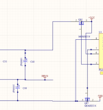
Attached is a preliminary schematic of a return-to-zero FIRDAC I intend to build. No idea when I will find time to design a PCB, stuff it and debug it, but I'll get there eventually. It will be a DAC that can only handle raw DSD. If it works well I may or may not decide to also make a PCM version that uses an FPGA board to convert PCM to sigma-delta modulates.

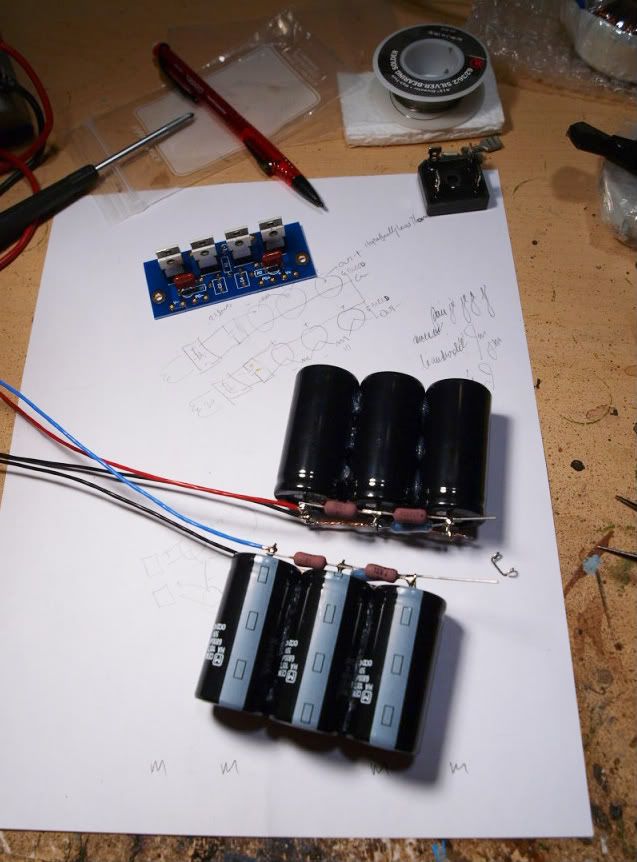
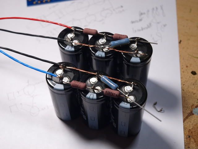
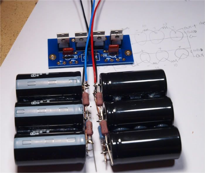
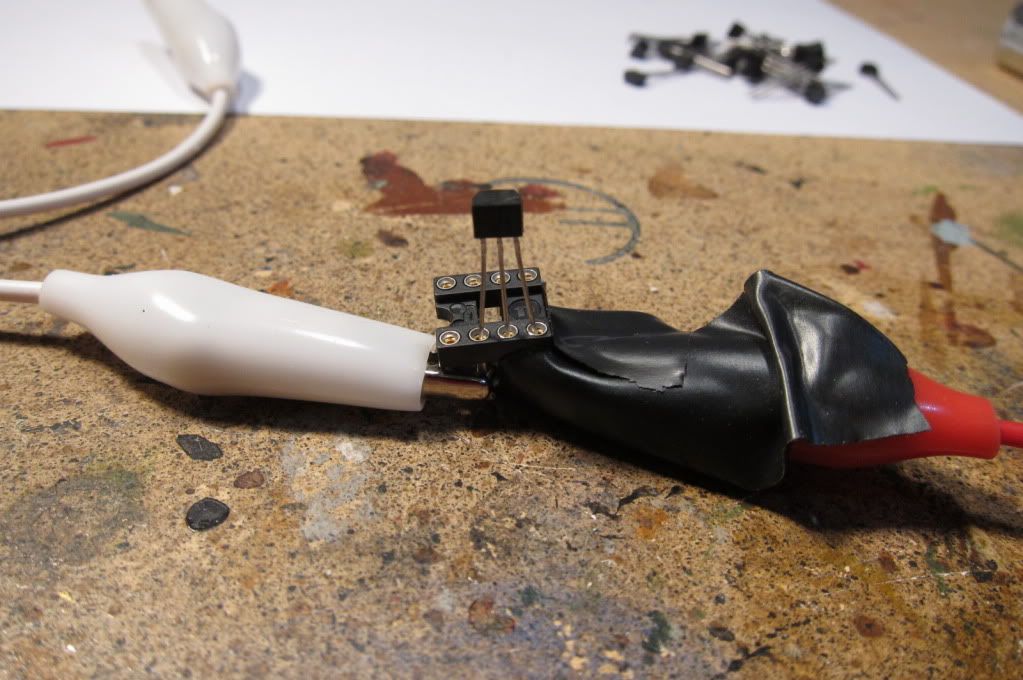
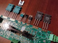
The circuit with the stacked dual transistors on page 2 is (or at least should be) a low-noise bandgap reference. I have the concept from D. F. Hilbiber's article in ISSCC Digest of Technical Papers from 1964, see https://www.diyaudio.com/community/...ith-ic-voltage-regulators.359652/post-7021353 It should have better noise performance than almost all modern bandgap references, because those almost always amplify a VBE difference by a large factor instead of stacking 
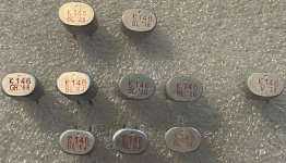
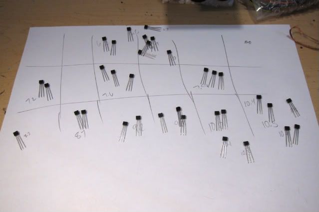
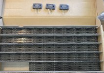
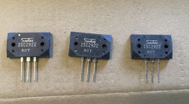
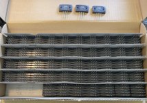
VBE differences. Only half the transistors are needed; I can't predict whether the BCM56DS or the NST45011 stacks will work best and they don't have the same footprints, so I want to reserve space for both.

The reason I can't predict whether the BCM56DS or the NST45011 stacks will work best is lack of information about the base resistance of the BCM56DS. It's a matched pair of medium-power transistors, so chances are that the base resistance is low, but I can't be sure of that. The NST45011 is specified to have a 1 dB typical noise figure at a 1 kohm source resistance when biased at 0.1 mA, which implies a base resistance of about 130 ohm, which is not bad but not very good either. (There are matched transistor arrays from THAT and Analog Devices with good and clear noise specifications, but I find those much too expensive.)

The fifth page has a clock doubler and a return-to-zero circuit, among other things. JohnW doesn't like the RTZ circuit I used in 74AHC02 and 74AHC08 DAC with 97 dB(A) dynamic range because he is afraid that the switching of the flip-flop may disturb the gate output signal when the flip-flop isn't slow enough. To avoid that issue, in this circuit, I split the RTZ logic from the actual DAC.

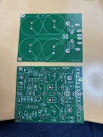
74LV574A's connected as shift registers on the third and fourth pages are the logic circuits used as DACs, they have low-noise reference supplies that are separate from the RTZ logic supply. As they run on a doubled clock and there are zeros inserted between each pair of data bits, simple shift registers work as RTZ FIRDACs. It's like the DSC2 DACs, but with return to zero. It's a balanced four-tap FIRDAC, balanced to keep the load on the reference supply as data-independent as possible. For matching reasons, I've connected the 74LV574A flip-flops in an ABABABAB style, with a second 74LV574A in BABABABA style.

Regards,
Marcel

Edit, 12 May, 1 October, 14, 15, 22 November 2022, 1 and 12 February, 26 May, 16 July, 1, 3, 6 and 8 August, 17 and 18 September, 15, 17 and 22 October 2023, 6, 10, 21, 29...31 March, 1, 8 and 15 April, 2 and 18 May, 28 July, 26 October, 1 and 7 November, 2, 3 and 9 December 2024, 9, 11, 15 and 16 January and 8 June 2025:
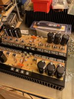
See posts #20 and #21 for the version (DAC3_5.pdf) I built and did some measurements on (using NE5532's rather than OPA1678's in the filter because the latter were out of stock), see post #1931, https://www.diyaudio.com/community/threads/return-to-zero-shift-register-firdac.379406/post-7483396 , for the latest BOM and schematics, and see post #241 https://www.diyaudio.com/community/threads/return-to-zero-shift-register-firdac.379406/post-7175580 and its links for the latest layouts. The latest schematic versions are DAC3_10_holdtimefix.pdf and DAC3filter_6.pdf. Versions 9 and 10 of the DAC layout (with or without hold time fix - the fix only consists of four resistors with updated values) are meant for 0.21 mm PR7628 prepreg, the earlier versions for 0.36 mm. See post #272 https://www.diyaudio.com/community/threads/return-to-zero-shift-register-firdac.379406/post-7182183 for the (old-fashioned) KiCad files.

I corrected the literature reference in this opening post.

Measurements:

The most relevant measurements are in posts #35, #60 (noise floor), #75, #79, #88 and #764 (distortion and noise floor driven from an Amanero), https://www.diyaudio.com/community/threads/return-to-zero-shift-register-firdac.379406/post-7403333 The measurements of post #764 were done by Hans Polak. Some measurements by bohrok2610 on a variant of the DAC can be found in post #955, https://www.diyaudio.com/community/threads/return-to-zero-shift-register-firdac.379406/post-7417293 and post #1090, https://www.diyaudio.com/community/threads/return-to-zero-shift-register-firdac.379406/post-7419240 , and an overview of measured noise floors in post #1092, https://www.diyaudio.com/community/threads/return-to-zero-shift-register-firdac.379406/post-7419247 It seems that the noise floor is quite sensitive to far-off phase noise and spurious tones on the clock. Later measurements by bohrok2610 on his variant with an improved board layout can be found in post #1928 and a few posts below it, https://www.diyaudio.com/community/threads/return-to-zero-shift-register-firdac.379406/post-7481890

See also bohrok2610's measurements on low-signal-level distortion and 10 kHz distortion starting at post #2467, https://www.diyaudio.com/community/threads/return-to-zero-shift-register-firdac.379406/post-7635702

For comparison, using the same sigma-delta modulator, the DSC 2.5.2 has low-level distortion with a similar looking spectrum, but about 20 dB worse, see https://www.diyaudio.com/community/threads/simple-dsd-modulator-for-dsc2.370177/post-7407497

On the other hand, ska managed to make a DAC with a similar spectrum but about 20 dB lower distortion products, apparently using a very simplistic approach. The sigma-delta modulator design is different, so the difference might be due to the DAC itself or due to a different dithering scheme in the sigma-delta modulator or both. The information about ska's design and layout is sparse, but there is some information spread out over posts #3834, #3837, #3844, #3847, #3850, #3851, #3863, #3865 and #3887. See also ska's thread about the same DAC, but with a better sigma-delta modulator, https://www.diyaudio.com/community/threads/discrete-fpga-dac-project.407618/

The measured noise of the bandgap reference with BCM56DS is smaller than the calculated noise with the NST45011, so the BCM's are the winner. Hence, in version DAC3_9, the NST45011's have been removed.

Hold time fix:
Measurements from Markw4 showed that the delay of U22, U24, U26 and U27 was only 1.7 ns, shorter than the anticipated typical delay and quite close to the 1.5 ns minimum hold time required by the SN74LV574As. Reasons may be the fact that I designed the circuit using TI data but switched to Nexperia for U22...U27 because the TI parts were not available, and that U22...U27 see a smaller capacitive load than the 50 pF used for the datasheet measurements. To fix this, R124, R127, R129 and R131 have been increased from 39 ohm to 270 ohm.

The prototype is fully functional with the original 39 ohm, with 270 ohm and even with 560 ohm. This last value is not recommended because it could lead to set-up time issues, I just tried it as an experiment. The noise floor with 270 ohm resistors is in post #1927, https://www.diyaudio.com/community/threads/return-to-zero-shift-register-firdac.379406/post-7481723

Supply currents:
The measured supply currents of the prototype at 27 Mbit/s are in post #88, https://www.diyaudio.com/community/threads/return-to-zero-shift-register-firdac.379406/post-6999623 Add 50 % to have some margin for exemplaric spread.

Supply sequencing:
There are some supply sequencing requirements, fortunately ones that can easily be met. Again see post #88, https://www.diyaudio.com/community/threads/return-to-zero-shift-register-firdac.379406/post-6999623 , for details.

Alternatives to components:
The TQ2-12V relays can be directly replaced by Zettler AZ850-12 relays, which are sold by Conrad (among others).

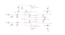
The latest filter design has NE5532's instead of OPA1678's in the second and third stages of its schematic, because the prototype also used NE5532's. Both should work, as the filter was originally designed for OPA1678's.

The OPA210 and OPA2210 could be replaced with OPA209 and OPA2209, respectively. They are very similar, although some specs of the OPA209 and OPA2209 are slightly worse. If neither OPA2210 nor OPA2209 is available, OPA1602 should also be usable as an alternative.

Header length:
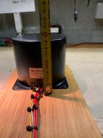
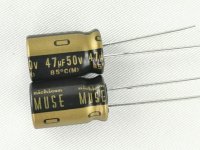
The headers connecting the filter PCB to the main PCB have to be relatively long because of the height of the capacitors used in the reference buffers. I hope the ones suggested in the latest BOM are the right size, I guess they are as I didn't get any complaints.

Skipping the last filter stage if DC offset doesn't matter:
You can skip the last filter stage if some DC offset is acceptable, for example because the offset is blocked somewhere further down the signal chain. On the filter board, you can then skip U6 and U13 with the surrounding components and connect the outputs of U5 and U12 straight to the 49.9 ohm resistors. Ray (nautibuoy) made filter boards without the last stage, see posts from #647, https://www.diyaudio.com/community/threads/return-to-zero-shift-register-firdac.379406/post-7365893

Output signal level:
A 0 dB DSD sine wave produces a differential output voltage of about 2 V RMS.

.dsf test files:
See post #762, https://www.diyaudio.com/community/threads/return-to-zero-shift-register-firdac.379406/post-7403044 , for .dsf files with repetitive silent patterns, these can be useful for measuring just the analogue circuit noise (without the effects of the ultrasonic quantization noise). See post #2610, https://www.diyaudio.com/community/threads/return-to-zero-shift-register-firdac.379406/post-7643831 , for a Pascal program that generates a non-repetitive silent DSD512 .dsf file. With small modifications, the Pascal program can also generate a tone.

The program and .dsf file attached to post #2696, https://www.diyaudio.com/community/threads/return-to-zero-shift-register-firdac.379406/post-7652259 , are meant for checking to what extent a DAC generates intermodulation products between idle tones around half the sample frequency.

Variants:
Besides Ray with his simplified filter board layout, there are others who designed variants:

post #429, PCM variant for Raspberry Pi by Thorp, https://www.diyaudio.com/community/threads/return-to-zero-shift-register-firdac.379406/post-7272503

posts #955, #1923 and #1928, single-board version by bohrok2610, https://www.diyaudio.com/community/threads/return-to-zero-shift-register-firdac.379406/post-7417293
https://www.diyaudio.com/community/threads/return-to-zero-shift-register-firdac.379406/post-7481890

post #1847, latest version of Markw4's mix and match between my DAC and stuff from Andrea Mori and others, https://www.diyaudio.com/community/threads/return-to-zero-shift-register-firdac.379406/post-7455840 See also his summary post #1880, https://www.diyaudio.com/community/threads/return-to-zero-shift-register-firdac.379406/post-7457164

bohrok2610 did some experiments with the filter to reduce the harmonic distortion at 10 kHz from about 0.003 % to even less, see post #2238, https://www.diyaudio.com/community/threads/return-to-zero-shift-register-firdac.379406/post-7620060 for an overview, and see post #2380 https://www.diyaudio.com/community/threads/return-to-zero-shift-register-firdac.379406/post-7625079 for information that is more recent than the overview, and that seems to refute my hypothesis in post #2238, although a later measurement seems to confirm it.

The schematics of the filters he tried are here: https://www.diyaudio.com/community/threads/return-to-zero-shift-register-firdac.379406/post-7635719 and here (well, a description actually): https://www.diyaudio.com/community/threads/return-to-zero-shift-register-firdac.379406/post-7680453

He also did many most interesting experiments related to distortion at low signal levels as well as 10 kHz distortion. There is a whole series of posts related to this, starting with post #2467, https://www.diyaudio.com/community/threads/return-to-zero-shift-register-firdac.379406/post-7635702 An attempt at explaining the results can be found in my post #2485, and an extended and updated version in the pdf file attached to post #3265, https://www.diyaudio.com/community/threads/return-to-zero-shift-register-firdac.379406/post-7686002

Markw4 made a DAC board layout with some extra test points, see post #2620, https://www.diyaudio.com/community/threads/return-to-zero-shift-register-firdac.379406/post-7645321

Hans Polak suggested making the FIRDAC longer by cascading the two SN74LV574A's. A longer FIRDAC is less sensitive to the phase noise floor (not to be confused with close-in phase noise), but doing it according to Hans's proposal has the disadvantage that the suppression of data-dependent reference current gets worse. A calculation shows that the suppression around odd multiples of half the sample rate (where you need the suppression most because of idle tones) theoretically remains intact, see post #3428,
https://www.diyaudio.com/community/threads/return-to-zero-shift-register-firdac.379406/post-7729904 All in all, I cannot predict whether Hans's version would be an improvement or a degradation.

If you are good at lifting SMD IC pins, it can be made on the original PCB, as Hans pointed out in post #3433, https://www.diyaudio.com/community/threads/return-to-zero-shift-register-firdac.379406/post-7730150 He explained in more detail how to lift pins in post #4038, https://www.diyaudio.com/community/threads/return-to-zero-shift-register-firdac.379406/post-7887181

2A3SET tried Hans's suggestion and subjectively likes the result, see post #4047, https://www.diyaudio.com/community/threads/return-to-zero-shift-register-firdac.379406/post-7896594 More information about 2A3SET's set-up, including a fully passive reconstruction filter, can be found in posts #4052 ... #4060.

I started working on a filter with more passive filtering, but so far never really finished it. That is, I made a prototype with one working channel on perfboard, but never made a PCB for it. See posts #3028, https://www.diyaudio.com/community/threads/return-to-zero-shift-register-firdac.379406/post-7672339 , #3138, https://www.diyaudio.com/community/threads/return-to-zero-shift-register-firdac.379406/post-7681475 , and #3304, https://www.diyaudio.com/community/threads/return-to-zero-shift-register-firdac.379406/post-7692816

However, bohrok2610 did build and measure the DAC with a filter with more passive filtering based on post #3028 but implemented with an OPA1632, see post #3100, https://www.diyaudio.com/community/threads/return-to-zero-shift-register-firdac.379406/post-7680453 He didn't see much (or even any?) improvement.

Calculations:
The way the original filter was designed is documented in sections 1 ... 5 of the attachment of post #3028,
https://www.diyaudio.com/community/threads/return-to-zero-shift-register-firdac.379406/post-7672339 Section 6 contains calculations on how to combine a passive LC filter with an MFB stage.

The attachment of post #2269, https://www.diyaudio.com/community/attachments/jitterfirdac_en-pdf.1282828/ , might be useful for people who want to design longer FIRDACs.

Quasi-multibit digital sigma-delta modulator:
The low-level distortion products bohrok2610 found do not occur when the digital input signal comes from a properly dithered quasi-multibit modulator. See post #4043, https://www.diyaudio.com/community/threads/return-to-zero-shift-register-firdac.379406/post-7895559 for the latest version of an implementation on a cheap FPGA.

Unfortunately, there are still some bugs in this version. The state variable limiting turns out to be inadequate for the SevenofNine mode and the modulator sometimes produces excessive noise even when it is not in SevenofNine mode. To be continued...

Suggestions for further improvements:
Even though the DAC works quite well, there are suggestions for further improvements all over the place in this thread, too many to link to in this opening post. I've commented on some of them in post #3526, https://www.diyaudio.com/community/threads/return-to-zero-shift-register-firdac.379406/post-7747974

As mentioned, another potential improvement would be to make the FIRDAC longer to make it less sensitive to the phase noise floor (not to be confused with close-in phase noise). When this is done by using longer shift registers while keeping all measures to cancel out data-dependent reference current in place, it should reduce the audio noise floor you get with an imperfect clock.

first PA build reccomendations

Hello people,

I am a begginer in DIY Audio and i am looking to build my first PA system. I am in need for a complete setup reccomendation. My requirement at this point is to cover outdoor events for about 200 - 300 people and the budget is around 5-7k euros. We play electronic music mostly Techno, House, Trance etc. The PA will be mainly powered by generators. As a base to build from i was thinking of something like 4x18 inch subs (with a quick search the xoc1 th-18 caught my eye, any other suggestions are welcome off course). So from there... what else will i need in terms of mid and hf speakers? What would be a complete setup with amps included?

Thanks in advance ✨

Audio Research VM-220 Tube Cages Needed

Howdy folks!. Im in search of a pair of tube cages for my Audio Research VM-220 monoblock tube amps. Being that these cages are hard to find, is there anyone out there who custom builds or makes aftermarket tube cages for high end tube amps?. Please let me know, as I’m in desperate need of a pair. Thanks very much.

Attachments

  • IMG_0875.jpeg
    IMG_0875.jpeg
    679.8 KB · Views: 61

Panamax M4300-EX weird ground loop do I need a new one?

I have 7 devices plugged in, if my preamp (tube based self built) and chip amp (LM3886 self built) are in the "always on" bank I get ground loop hum. I get it if either is in the "always on" bank. If I put them both in the switched bank the ground loop goes away. Changing the way the other 5 devices are plugged in doesn't change the hum.

This started a few weeks ago so something has changed and I wonder if something internal in the Panamax is the issue. It is dead quiet with the amp/preamp in the switched band but I wonder if I should just replace it. I bought it years ago pretty cheap used.

I don't really care much about the filtering I just need a decent strip of outlets. Any recommendations?
M4300 hum.jpg

Cathode followers stage and interstage transformer

I was wondering if something along these lines might work well. I have 2pair of well made small signal type transformers. I was considering a 12AU7 as a cathode follower with an out put around 400ohms impedance driving the 600ohm side of my interstage transformer and then taking the 25ohm side of said transformer to drive my output tube. Well what type of performance/general behavior I might I observe- not so mush will it work as opposed to how well it would work

Attachments

  • IMG_2439.jpeg
    IMG_2439.jpeg
    842.4 KB · Views: 108

3D-Printig of transformer bobbins

Hi,

flanged bobbins for winding conventional iron core transformers are becoming increasingly hard to find in the right sizes and implementations. I'd like to examine sliced OPT winding and compare with conventional interleaving. Hence, I need bobbins with three or more chambers. Is fused deposition modeling a viable way to make them, despite the thermoplastic filaments? Which material would be preferred here? Or is stereolithography in general the better way, 'cause the resin doesn't need melting and the component isn't necessarily thermoplastic?

Best regards!

Hello everyone

Hello everyone,

I am Hans from Germany.
I've been into DIY audio in my youth, but as time went on, life happened, and priorities changed.
I've now arrived at a point in my career (engineering adjacent, btw..), where I can dedicate more time to non-work related things, which eventually revived my interest in DIY audio.

Scrolling through the forum, I was impressed by how elaborate some DIY electronics projects have become.

I'm mostly interested in digital electronics, dsp, switching amps, and PSUs.
Hoping to gain some inspiration for my own future projects 🙂

Hans

Help with Ian Canada streamer kit

Hi all, hoping someone might be able to assist me here. This is my first venture into DIY audio.

I’ve purchased a raspberry pi streamer kit from Ian and am having issues getting it to play music/ my DAC to recognise it.

It is this kit here: https://iancanada.ca/products/flags...rk-music-streamer-kits?variant=47606889185580

The one that comes with the HDMIPI Pro II

I have my Holo Spring 3 i2s set to Alt 2

Have Ropieeexl installed and roon can see the endpoint with certain HAT settings (I’ve been using Raspberry pi default i2s).

This is the HDMI cable I’m using: https://www.jaycar.com.au/concord-0...hHlge7agwbTutWWPfyrPlS_dAV6MKYBSqKNcsiolhPbNv

I’m using the ifi ipower mk2 to power it.

Here’s a few photos of the build in case there’s something visually that I might have done wrong

Thanks all

IMG_2894.jpeg
IMG_2895.jpeg
IMG_2896.jpeg
IMG_2899.jpeg
IMG_2900.jpeg
IMG_2904.jpeg
IMG_2903.jpeg

Sphinx Project Fourteen help wanted

Dear all,

Recently a Sphinx amplifier entered my workshop. It is a model 14 with 2 tubes and Mosfet's in the amplifier stage. These are the 2SJ50 and the 2SK135, very famous in Holland in the 80's when Elektuur came out with the Cresendo amplifier for diy purposes and these mosfet's.
The tubes are ECC88

The reputation of the 14 is not so good. Later, Sphinx made a rebuild which was more reliable. The biggest problem is the design of the PCB and the power supply for the tubes. But the sound is fantastic!

Well, my question, does anybody have a diagram for this amp?

Thanks in advance for the help and i'll keep you folks posted.

Ah, the problem is loud hum and oscillation.

Attachments

  • IMG_1714.JPG
    IMG_1714.JPG
    778 KB · Views: 677
  • IMG_1715.JPG
    IMG_1715.JPG
    794.2 KB · Views: 525

Thorens outdoor plug-in Power Supply (AC/AC Adaptor) for TD 180-280-316-318-320-321 suited for Wall AC Power Plugs - various Advices and Questions

There are different wall wart AC/AC adaptor power supplies over the world according this service manual for TD316-318-320-321 and Phantasie: - go to
https://archives.doctsf.com/documents/afficher_document.php?num_doc=106001&num_fic=1
(on page 14)

discovered under
https://archives.doctsf.com/documents/index.php?num_serie=56&marque=1296

1) order code 4 150 083 (Euro 220V 50Hz)
2) order code 4 150 078 (Japan 95V, 50/60Hz)
3) order code 4 150 077 (CSA 120V, 60Hz - maybe a miss print - it must actually be "USA" for the United States - maybe not, if CSA stands for Canadian Standards Association - so I think)
4) order code 4 150 064 (UK 240V 50Hz)

Even on the genuine Thorens versions of these plug-in power supplies are not to read this Thorens order code (at least concerning the European versions) - but instead the Thorens order code this:
1) FRIWO (German Brand for power supplies) Type "FW6199", 16V~/160mA (actually it must be "Series FW6199", because under this series were many other voltages available)
2) BARTEC (also German Brand for power supplies) Typ "A7-1231-1508", 16V~/160mA
All this versions for 220V~ input.

Because a friend of me want to have no cheap copies from China and no SMPS version as replacement I tried to take a closer look at this versions.
I discovered thereby that even the 50Hz transformer versions manufactured in Germany are sealed rather than screwed together (go to image 1-6). This has the disadvantage that if a thermal fuse blows or there are contact problems, there is no way to repair it without violating safety regulations.
By chance I noticed that there is also a screwed version from FRIWO (series FW6299 order code 4569100) with the same voltage, but with a higher maximum current delivery capacity, which is more of an advantage but in any case not a disadvantage (made for TIPTEL "LETTERA-F")

However, the different voltages in stopped mode (i. e. without load) must be taken into account on TP1 - see service manual for TD316-318-320-321 on page 9 and schematic diagram on page 10+12. As long the main capacitor C101 (1000/25) behind the rectifier unit GR101 was replace by a higher voltage (I recommend for C101 in general a 63V version include a bypass WIMA MKS between 0µ33 and 0µ56 resp. 330n-560n) there are no issues to expected.
OTOH - due the fact, that the input voltage of the FW6299 version is 230V~ (instead 220V~ of the FW6199 version) go to image 7-11.
the deviations in voltage to the mentioned values in the service manual are probably not too great.

I ordered one for him in a 16V~ version from screwed FW6299 series in used condition and he had good experiences with it (same version as in the attached images). Actually this plug-in power supply version is original made for this answering machine: Tiptel model "LETTERA-F" - go to
https://www.lipinski-telekom.de/fil...06-21_Anrufbeantworter_Tiptel_LETTERA_F_V.pdf
Due the fact, that there are offers of the complete set-up are cheaper, it is sometimes better to looking under this naming instead under FW6299 and 16V~.

Now I have check a 14V~ version (also series FW6299 order code 4569120, made for Tiptel 270 cord phone go to image No 12-15) and here the measured AC voltage values on a TD320:
AC-values at 233VAC mains voltage: 14,8V~ without load and 14,3V~ with running turntable motor on 33rpm and 45rpm
DC-values at TP1 (C101) : 0V without load and 17,9VDC with running turntable motor on 33rpm and 45rpm
The 0V without a rotating motor is caused by the fact that my TD320 model has a newer circuit board in use compared to the version in the service manual. In opposite to the older versions the speed selector switch is the on-off switch at the same time and interrupt the PCB trace between the AC pins and rectifier input.
Go to the images in post #16 under
Thorens TD 320 Power Supply
here on this forum.

P.S.: Under
https://aukro.cz/napajeci-adapter-pro-gramofony-thorens-pro-ject-16v-0-5a-7085015872
are mentioned this brands and models as compatible to this THORENS in wall AC power supply with Thorens order code 4 150 083 - OTOH there are to find partly different order codes in the service manuals:
PRO-JECT AD4120-16.0-500
PRO-JECT PRO-NT16/500
PRO-JECT 1 XPRESSION III COMFORT
PRO-JECT DEBUT III
PRO-JECT XTENSION 12 EVOLUTION
PRO-JECT XTENSION ORTOFON RS/AS
THORENS 4 150 083
THORENS FW6199
THORENS Z 4 150 083
THORENS TD 146 (50Hz: 4 150 060 FW5003 10V~ 300mA, 60Hz: 4 150 077, page 8 - page 24 show voltages on testpoints)
THORENS TD 147 (50Hz: 4 150 060 FW5003 10V~ 300mA, 60Hz: 4 150 077, page 8 - page 24 show voltages on testpoints)
https://archives.doctsf.com/documents/afficher_document.php?num_doc=105996&num_fic=1
TD145/160/165 (Series I) TD145/160/166 (MK-II ISOTRACK)
https://medias.audiofanzine.com/files/ve-thorens-145-166-service-480347.pdf
THORENS TD 166
THORENS TD 166 MK II
#https://medias.audiofanzine.com/files/ve-thorens-145-166-service-480347.pdf
THORENS TD 180 50Hz: Z4 150 083
https://archives.doctsf.com/documents/afficher_document.php?num_doc=105997&num_fic=1
THORENS TD 2001 50 Hz: 4 150 083
https://elektrotanya.com/thorens_td_2001.pdf/download.html
THORENS TD 2001 BC
THORENS TD 280
THORENS TD 280 MK II
THORENS TD 280 MK IV 50 Hz: 4 150 083
https://archives.doctsf.com/documents/afficher_document.php?num_doc=105999&num_fic=1
THORENS TD 295 MKIV
THORENS TD 3001
THORENS TD 3001 BC
THORENS TD 316
THORENS TD 316 MK III
THORENS TD 318
THORENS TD 318 MK III
THORENS TD 320
https://archives.doctsf.com/documents/afficher_document.php?num_doc=106001&num_fic=1
http://thorens-info.de/html/federung.html
THORENS TD 320 MK II
THORENS TD 321
THORENS TD 321 MK II
THORENS TD 325
THORENS TD 520 50 Hz: 4 150 084 (page 8 serv.man)
THORENS TD 520 MK II 50 Hz: 4 150 084 (page 8 serv.man)
THORENS TD 521 50 Hz: 4 150 084 (page 8 serv.man)
https://archives.doctsf.com/documents/afficher_document.php?num_doc=106002&num_fic=1

Under
http://thorens-info.de/html/seiten-ubersicht.html
you will find a good model overview (line up) of the whole Thorens record player range.
But I am looking for an overview of all motor control PCB's and their versions.

I don't understand, why for the TD146+TD147 the power supply sticker of FW5003 show only 10V~ although the service manual mentioned higher voltage values (Thorens order code 4 150 060) - check out the attached images No 16-19 and this images under
http://www.hifi-forum.de/viewthread-26-17011.html#11 (TD147 don't rotate sometimes)

Attachments

  • Thorens-FRIWO 4 150 083 FW6199 16V-160mA-I.webp
    Thorens-FRIWO 4 150 083 FW6199 16V-160mA-I.webp
    104.1 KB · Views: 87
  • Thorens-FRIWO 4 150 083 FW6199 16V-160mA-IV.webp
    Thorens-FRIWO 4 150 083 FW6199 16V-160mA-IV.webp
    100.4 KB · Views: 86
  • Thorens-FRIWO 4 150 083 FW6199 16V-160mA-II.webp
    Thorens-FRIWO 4 150 083 FW6199 16V-160mA-II.webp
    94.3 KB · Views: 84
  • Thorens-FRIWO 4 150 083 FW6199 16V-160mA-III.webp
    Thorens-FRIWO 4 150 083 FW6199 16V-160mA-III.webp
    27.8 KB · Views: 83
  • Thorens-BARTEC 4 150 083 A7-1231-1508 16V-160mA-II.webp
    Thorens-BARTEC 4 150 083 A7-1231-1508 16V-160mA-II.webp
    35.9 KB · Views: 82
  • Thorens-BARTEC 4 150 083 A7-1231-1508 16V-160mA-I.webp
    Thorens-BARTEC 4 150 083 A7-1231-1508 16V-160mA-I.webp
    65.2 KB · Views: 82
  • FRIWO FW6299 4569100 tiptel 16V-300mA-II.webp
    FRIWO FW6299 4569100 tiptel 16V-300mA-II.webp
    327.9 KB · Views: 85
  • FRIWO FW6299 4569100 tiptel 16V-300mA-I.webp
    FRIWO FW6299 4569100 tiptel 16V-300mA-I.webp
    384 KB · Views: 78
  • FRIWO FW6299 4569100 tiptel 16V-300mA-III.webp
    FRIWO FW6299 4569100 tiptel 16V-300mA-III.webp
    93.4 KB · Views: 82
  • FRIWO FW6299 4569100 tiptel 16V-300mA+LETTERA-F.jpg
    FRIWO FW6299 4569100 tiptel 16V-300mA+LETTERA-F.jpg
    24.1 KB · Views: 84
  • FRIWO FW6299 4569100 tiptel 16V-300mA+LETTERA-F-II.webp
    FRIWO FW6299 4569100 tiptel 16V-300mA+LETTERA-F-II.webp
    144.7 KB · Views: 81
  • FRIWO FW6299 4569120 tiptel 14V-270mA.webp
    FRIWO FW6299 4569120 tiptel 14V-270mA.webp
    99.3 KB · Views: 85
  • FRIWO FW6299 4569120 tiptel 14V-270mA-II.webp
    FRIWO FW6299 4569120 tiptel 14V-270mA-II.webp
    62.4 KB · Views: 88
  • FRIWO FW6299 4569120 for Tiptel 270 14V-270mA.webp
    FRIWO FW6299 4569120 for Tiptel 270 14V-270mA.webp
    176.8 KB · Views: 88
  • original-netzteil-tiptel-4569120-output-14v-270ma-fuer-tiptel-270.jpg
    original-netzteil-tiptel-4569120-output-14v-270ma-fuer-tiptel-270.jpg
    62 KB · Views: 86
  • Thorens-FRIWO 4 150 060 FW5003 10V-300mA-I.jpg
    Thorens-FRIWO 4 150 060 FW5003 10V-300mA-I.jpg
    168.5 KB · Views: 83
  • Thorens-FRIWO 4 150 060 FW5003 10V-300mA-II.jpg
    Thorens-FRIWO 4 150 060 FW5003 10V-300mA-II.jpg
    166.6 KB · Views: 89
  • Thorens-FRIWO 4 150 060 FW5003 10V-300mA-III.jpg
    Thorens-FRIWO 4 150 060 FW5003 10V-300mA-III.jpg
    227.1 KB · Views: 87
  • Thorens-FRIWO 4 150 060 FW5003 10V-300mA-IV.webp
    Thorens-FRIWO 4 150 060 FW5003 10V-300mA-IV.webp
    110.6 KB · Views: 84

NICHICON capacitors KZ MUSE , FG FINE GOLD series for sale

I have for sale some NICHICON CAPACITORS

KZ SERIES MUSE High Grade( Obsolete capacitors )
FG SERIES FINE GOLD ( Obsolete capacitors )

Original photo

Payment: PAY PAL
Registered priority ( box + antistatic bags )
Shipping to EUROPE 7,5 USD
Rest of the worlds: 8,50 USD

If you buy for 50 USD or more shipping is free.

Multiple purchases - ONE shipment

Minimal order quantity = 30 USD


KZ series ( PREMIUM GRADE CAPACITORS )


1) 47uF/50V 0,42 usd each
2) 100uF/25V 0,45 each
3) 100uF/50V 0,58 each
4) 220uF/25V 0,58 each
5) 470uF/25V 1,00 each

FG series ( HIGH GRADE CAPACITORS )

1) 100uF/63V 0,80 each

Attachments

  • KZ 47uF 50V małe.jpg
    KZ 47uF 50V małe.jpg
    91 KB · Views: 55
  • KZ 100uF 25V małe.jpg
    KZ 100uF 25V małe.jpg
    69.9 KB · Views: 56
  • KZ 220uF 25V małe.jpg
    KZ 220uF 25V małe.jpg
    81 KB · Views: 56
  • KZ 470uF 25V małe.jpg
    KZ 470uF 25V małe.jpg
    67.8 KB · Views: 58
  • KZ 100uF  50V małe.jpg
    KZ 100uF 50V małe.jpg
    94.3 KB · Views: 56
  • FG 100uF 63V małe.jpg
    FG 100uF 63V małe.jpg
    105.1 KB · Views: 56

Sound, Vision and a Social Enterprise Idea

The purpose of this thread is to share an idea and engage with diyAudio community's members before deciding to commit. In short, it's an idea to sell Hi-Fi amplifier PCBs and donate half of the profit to OneDollarGlasses social enterprise and half to that of a participating members' own choice.

As age takes a toll on eyesight, I recall a month-long stay in the Kashmir region enjoying high alitutude trekking. On that adventure I came across families working as a cooperative with two or three generations sharing the work of intricate carpet weaving. 40 years on this memory still sticks with me: 1) because of my deteriorating eysight; and 2) the less savoury memory of so-called Do Gooders' crying Foul about Child Labour abuse. I recall seeing happy families put food on the table and spend the spare cash on sending their kids to school. With an optician likely beyond budget and hours away by bus, children, with their keen eysight, helped save families from hardship. Juxtaposition, those who had lost family or friends begged on the street!

On the theme of eyesight, I take my hat off to Martin Aufmuth the founder of OneDollarGlasses [https://www.eindollarbrille.de/en]. The social enterprise he founded enables people living in remote areas to get a skill (measure vision and construct glasses) and provide a service promoting welfare in remote communities by providing hand-made prescription glasses. Accusation of child labour in the 80's & 90's might have been less vociferous if ageing parents could see well enough to continue the art of intricate Persian-style weaving. Give a man a fish and he'll feed himself - teach him to fish and he'll feed a family. OneDollarGlasses teaches vision assessment, spectacles constructing and enterprise enabling an income and provision of glasses to those in need.

I have an amplifier design which I believe will be of interest to those seeking to self-build. My vision is to establish a small number of hubs in N and South America, Europe, Asia and Australasia. Essentially, the Gerber file would be made available to hub leaders who would sell PCB online in their respective regions. I would like to lead but not micro-manage in order allow allow flexibility for this idea to grow in a way that is manageable by those who participate. Should you have an interest in participating, please reply. I will publish my schematic if enough people show an interest. One person I would be keen to connect with is someone who is more skilled than me in board layout. If there is enough interest to bring this to fruition a marketing plan is in the making. It includes the help of a couple of my pals, whose names and music you'll be familiar with, who have suggested they could lend their name(s) to my yet nameless project initiative. My goal is to be ready to launch my project by the end of this year.

Thanks for reading,

Terry

Weircliffe bulk tape (rtr) eraser - free - collection only York, UK

I'm having a clear out and have a lovely, historical Wiercliffe bulk reel-to-reel tape eraser to find a new home for. This is free to a good home, but must be collected from York in the UK. It's far too heavy to ship. It would be great to preserve this interesting piece of audio history, rather than it going to scrap.

The eraser is a large, nicely made wooden box containing a heavy AC electromagnet. It's complete with original instructions and is in really excellent condition for its age. However, I'm passing it on as a decorative item only. I do not encourage or condone anybody plugging this thing into the mains. The plug socket has been removed to reinforce this point!

Happy to answer any questions about it. Hopefully we can find it a new home.

20250419_115904.jpg20250419_115852.jpg
20250419_115950.jpg20250419_115959.jpg
20250419_115918.jpg

Dipole Ribbon with Front Horn?

Would mounting a horn on the front of a dipole ribbon cancel the positive attributes of dipole? Seems it would, but curious to know if anyone has experience with this or know of someone who has, and what their findings were.

Thought that got me here: the ribbon drivers I've seen have a natural roll-off at the bottom end, which negates their sensitivity.. when used in a dipole configuration, but can be lifted with a properly designed horn. I love the depth of sound from a dipole. Can I have my cake and eat it too??

Using older equipment on elevated mains voltage

Hello, in the past, in Europe the standard main voltage used to be 220 Volts. This mains power voltage has been increased over the years and at the moment it appears that the standard is 240V, raised again from 230V that used to be the standard in recent years.

When I measured my mains power voltage where I live, it is at times even 245 V, partly due to solar generated excess power when the sun shines brightly.

Now, the potential problems I face with these elevated voltages is with my older equipment. I use a diy tube amp with a power transformer (ex-Lafayette from the seventies) that is rated for 220V, and an older Rotel RB-850 power amp that is also rated for 220V. Besides that, I also use a Rotel RB-980BX amp that is rated for 230V. All according to the labels on the back. For the 220V tube amp it became obvious, that the B+ tension is too high when connected to 240V mains power and I use a variac (1000W) to bring the voltage back to 220V and the working voltage for the EL84 tubes back to 300V. I do have more tube amps from old times, when the mains power used to be 220V.

I would like to know what the (long term) consequences could be if older gear is exposed to elevated mains voltage. Is there a difference between solid state and tube amps? Does solid state amps may also "wear out" quicker or would it affect sound quality? What would be a good work-around besides a variac (may be bad for sound quality?). It is mostly not possible to rewire the power transformer because the needed taps are simply missing.

Thanks for the advise!

Main PSU cutoff after filter caps using mosfets in few micro seconds any suggestions on the current approach

Im building a mosfet power amplifier with IRFP240 and 9240 in the output stage with even 7 or 10 pairs but my point of concern is to turn off the power supply after the psu bank just to cutoff when over current is detected at the source resistors either by short or any other damaging conditions. Now since Mosfet OPS is quite fast in getting damage we need fast cutoff of power supply in the order of less than 50 to 60 micro seconds. Initially thought of using photovoltaic devices to turn off the mosfets but they are not fast and finally thinking of using HCPL 3120 since its less than micro second turn of time and it also has higher current output to handle the gate charge of the mosfets which are used in the pos and neg rails. Any ideas will be very helpful.

Attachments

  • mosfet rail.PNG
    mosfet rail.PNG
    224.1 KB · Views: 114

System Pictures & Description / Subwoofer Gallery

In the full range and multiway forums there are threads dedicated to pictures and stickied to the top but not this one. With the variety of different subwoofer design options it seems like a pictures thread could be interesting. I for one would love to see everyone's subs in one place

Maybe the mods could chime in on this one

:cop:
(Mod note: Thread now in place as requested)

Logic Solutions for Iron Pre Kits

As suggested by Zen Mod, I have opened a new thread for discussing logic solutions to replace the original rotary switch and the plain volume pot.

Whether you want to control the relays remotely (Lazy Boyz) or from the front panel using Arduino, ATtiny, ESP32, or any other MCU, this is where to discuss it and ask questions.

Attenuators, whether it's remotely controlled or not, can also be discussed here. In fact, any deviation from the standard rotary input channel switch and/or the standard pot qualifies for discussion here.


Links to important information

The original Iron Pre threads:
https://www.diyaudio.com/community/threads/iron-pre-essentials-kits-for-the-diya-store-register-your-interest.390509
https://www.diyaudio.com/community/threads/whats-wrong-with-the-kiss-boy.293169/

Updated schematics and BOM of the Iron Pre kits: post #1 of the Iron Pre Essentials Kits thread

Modification of current boards (first batch) to allow switching of the relays via microcontroller.
SE version: Post Post #13
BAL version: Post Post #14

There is some valuable information about driving the relays using logic pins on MCU's in the Iron Pre Essentials Kits thread, starting with post #1,232 and maybe even before that.

PS: This post will be updated regularly to include important information.

ES9017/9027 DAC PCBs

Hi Everyone!
My newest ESS DAC design is almost finished. I will make a group ordering action if there are any intrested guys in this forum...
Detailed informations are soon available, or please simply ask...!

Attachments

  • DAC-Clock_1.PNG
    DAC-Clock_1.PNG
    44.6 KB · Views: 258
  • DAC-Filter_1.PNG
    DAC-Filter_1.PNG
    192.5 KB · Views: 255
  • ESS-DAC_1.PNG
    ESS-DAC_1.PNG
    127.7 KB · Views: 253

Altec 288-8G Compression Driver with Altec 805B Multicell

In this post I test Altec 288-8G Compression Driver with Altec 805B Multicell.

I borrowed the horn from my brother.

IMG_0002_480x480.jpg
IMG_0001_480x480.jpg


Specification

Compression Driver


  • 2.80" Diameter Voice Coil (71mm)
  • Aluminum diaphragm
  • 7.1" outside diameter for compression driver body
  • 29.3 lbs compression driver weight (13.3 Kg)
  • Alnico magnet
Horn

  • 40 x 80 coverage pattern
  • 500Hz Cutoff frequency (Fc)
  • 62cm wide x 34cm tall x 55cm deep
Measurements

Frequency Response


I measured the horn with a 2m mic distance. Above 1kHz my measurement is gated to 4ms using 1/24 octave smoothing. Below 1kHz the repones is ungated and 1/3 octave smoothing applied. Generally we see a reasonably smooth response with a midrange emphasis centered at about 2kHz. The horn loads strongly down to 400Hz with very little first order reflection near the the horn's cutoff frequency which is published as 500Hz. The diaphragm is breakup free until 13.5kHz.

Altec_805B_with_288-8_Compression_Driver_480x480.png


Below is the horizontal off-axis colored polar map using the same 2m mic distance.

Characteristics

  • 90 degree coverage (500Hz-1.5kHz)
  • Widens to 120 degrees (1.5kHz-17kHz)
  • High frequency output drops when measuring directly in front of each cell


Altec_805B_with_288_Compression_Driver_Horinzontal_Off-Axis_480x480.png


Time Domain

Conducted in the near field using a 20cm mic distance.

Altec_805B_with_288-8_Compression_Driver_CSD_480x480.png


The burst decay shows some stored energy in the treble region.

Altec_805B_with_288-8_Compression_Driver_BD_480x480.png


Distortion

I measured distortion with the 20cm mic distance. SPL level was set at 85dB and 95dB referenced at 1m. I set a fixed resistor L-pad using a 20w 7.5ohm and 1.5ohm (R1 & R2) which provides about -15dB attenuation. This brought the amplifier up out of its noise floor (Hypex FA500). Above 1kHz we see H3 and H4 at very low levels while H2 dominates. H3 for the 95dB signal is only 0.015% for the 1kHz region.

Altec_805B_with_Altec_288-8_Compression_Driver_85dB_1m_480x480.png


Altec_805B_with_Altec_288-8_Compression_Driver_95dB_1m_480x480.png


Multitone is shown below for the same 85dB and 95dB test signal levels.

The 85dB test signal shows 70dB dynamic range for the 1.5kHz region reducing to 60dB for the 10kHz region.

Altec_805B_with_Altec_288-8_Compression_Driver_85dB_1m_IMD_480x480.png


The 95dB test signal is unchanged for the midrange but we see 10kHz reduce to 50dB dynamic range.

Altec_805B_with_Altec_288-8_Compression_Driver_95dB_1m_IMD_480x480.png


Contour Circuit

The horn has a strong midrange presence along with some coloration near the horn's cutoff frequency. So I decided to develop a basic high pass filter along with a contour circuit. I settled on a LR3 high pass filter to eliminate the coloration in the 500Hz region. I then implemented an parallel LCR contour to bring down the 2kHz region. The raw response is shown in red, the blue response is with the LCR, and the green response is with the high pass filter.
Altec_805B_with_288-8_Compression_Driver_Crossover_Circuit_2567_480x480.png


Subjective Listening

With contour circuit No.2567 in place, I've summarized my listening impressions.

  • Spatial and enveloping treble due to 120 degree wide coverage
  • Despite the class D amplifier, the sound had some typical H2 smoothness.
  • Missing upper treble detail
  • Some horn coloration across its bandwidth
  • Strong presence on vocals (voice modulation easy to follow)
  • Some masking of soundstage depth
Overall the 288-8G with the 805B horn offers an entertaining and enjoyable listening experience if you can get past the slight horn coloration which masks overall clarity. A super tweeter may offer some resolution improvement for the upper treble, but the coloration through the midrange would still exist. For example the burst decay is shown below with the contour circuit in place. Perhaps there are methods to improve this which is beyond the scope of this post.

Altec_805B_with_288-8_Compression_Driver_Crossover_Circuit_2567_BD_480x480.png

NAD 3020 (1982/3) - loud pop when turning on

I have a NAD3020 (from new, bought in 1982 or 1983) that has recently developed a loud pop when turning on. This is the original, not the 3020A or later, as far as I can tell, but s/n A3257885 might reveal something else!

It makes no difference where the volume is set prior to turning on, but having the "Audio Muting" button in makes the pop much quieter.

Before I open it up and start checking things with a multimeter, which are the likely components that have failed?

Low voltage~∓15V, low power , high bandwidth amplifiers seeking

Hi everyone,
I'm trying to searching for an amplifier than can work well with low power supply like 15V dual rail or single rail and expected to able to output about 10~15W to 4ohm speaker with signal from my laptop.
Since i dont have any audio mosfet (which is hard to obtain in VietNam) so i hope it will use common BJT.
Thank you very muchh.

3 way sealed active speaker - I called it Fast³

Hello guys,

it's been a while now, but I finished the speakers! After reading all of your suggestions and studing the links you gave me in this thread, I decided to build active 3-way closed speakers.

The Dimension is 620x352x345 mm.

I used these speakers:
  • Monacor DT-300
  • B&C 6PEV13
  • Lavoce WAF123.01

As amplifiers, I have chosen two Sure Electronics JAB5 (4x100W), for each speaker 2 channels linked together for the woofer and 1 channel for each midrange and tweeter.
The amplifiers are powered by a MEAN WELL GST360B36-C6P 36VDC 10A 360W.

The name Fast³ stands for 3-way and the usage of F.A.S.T. (Fullrange and Subwoofer Technologie). As far as I know, the usual way to build fast speakers is a 2-way system with fullrange and woofer. But I thaugt, that it might work for 3-way, too.

So I have simulated the Lavoce WAF 123.01 in vituixCAD by using a Linkwitz Transform (further informations are available here @miniDSP or here @Linkwitz) and found out, that it will work, there are some big reserves in excursion.

WAF123_01_Simu_Linkwitz_Transform_SPL.jpg

WAF123_01_Simu_Linkwitz_Transform_Auslenkung.jpg


So I started with mechanical design on Fusion 360...

I asked the 3 manufacturers for 3D CAD drawings for the speakers, which was not a problem for at least Lavoce and B&C, only Monacor (old fashioned germans 😆) was not able to provide the drawing (the answer was - we don't have 3D CAD drawings). So for the Monacor, I just designed a dummy by myself.

DT300.jpg


Here is a CAD view of a loudspeaker. I've decided on a design where I miter cut the base, top and sides, leaving the back and front offset in the frame construction by an offset in material thickness. There is a compartment for the electronics on the back so that I can avoid any problems with sealing.

CAD-Frontansicht.jpg


The speaker cables are passed through the cabinets via plugs like these:

stecker.jpg


The midrange driver has an extra cabinet with approx. 5 l, the volume for the woofer results from the design and is approx. 41 l, which is also the value I got from the simulation.

woofer volume:

CAD_Volumen_TT.jpg


Here some pictures of the woodwork:

Fräsen_Seitenwand.jpg
Deckel.jpg
Anprobe_1.jpg


Glued together, a speaker looks like this, I colored the wood with teak stain:
Farbvergleich.jpg


unfortunatelly, I did a little error while gluing, you can see that on the right uncolored speaker, I had some small gaps (still sealed, but visible) I had to close. So I used liquid wood. After sanding and staining, I used the trick my daughter had hinted at. Dad, use a felt-tip pen! Said and done, experimented a little and then boldly colored the fine liquid wood joint with the empirically determined color. After oiling, you can't see anything or you have to get very close.

Links_Fertig.jpg


Nahaufnahme.jpg


I have housed all the electronics in an extra compartment in the right-hand speaker. The compartment is ventilated and is closed with an aluminum cover.

Elektronik.jpg


Here you can see the two JAB5s. The left amplifier in the picture is the master of disaster. The attentive reader will notice that there are no fans installed, because the active ones are really loud. I have calculated the necessary cooling capacity and installed appropriate heat exchangers for passive operation. I read on the Wondom or Dayton Audio website that you can unplug the coolers without anything happening (apart from visual, auditory and olfactory signaling)

I have to say that these coolers are a compromise, as my desired coolers are not available anywhere. Fischer wants 125€ + transportation + VAT because of minimum order value I would have liked 2 KSK1 coolers. So far it works well, I never measure more than 60°C on the heat sink.

The left speaker is reached via a Cordial 825. The cable is connected via Neutrik SpeakOn connectors, which are probably completely overengineered, but stable.

Next I had to mill the aluminium cover, where I have to admit, I have had some trouble:

Gitter.jpg


I had never milled aluminum before, know that my wood router is not as rigid as one made of metal and thought to myself, hey, go with little depth, decent speed and not quite as fast. With my Makita, that was 34,000 rpm, 0.5 mm depth adjustment and 1000 mm/min feed rate. I don't have any cooling.

The result was that the first depth cut was clean, the second was a disaster. As a joke, I described my result to ChatGPT and gave them my milling parameters and got the answer: depth cut to 1 mm, speed to 12,000 rpm, feed rate to 850. I thought to myself, ok, the workpiece is no longer usable anyway, so I defined a negative allowance of 0.5 mm in Fusion and ran the new G-code through the milling machine with the following result:

Gitter_2.jpg


Completelly assembled look:

Rückwand_rechts.jpg

Lautsprecher_Rechts.jpg


Lautsprecher_Links.jpg


The speakers are about 90% filled, I used Visaton mats as filling material. First I covered all the walls from the inside with cut-to-size mats and then, in the second step, filled the cavities with cut-to-size pieces so that the insulating material was distributed fairly evenly. I sealed the cable feed-throughs (single wires, barely drilled) with a few drops of glue.

Then I'll move on to Sigma Studio next.

Attachments

  • Links_Fertig.jpg
    Links_Fertig.jpg
    71.3 KB · Views: 34

For Sale Miscellaneous small transformers

None of these were ever used.
$45.00 for everything. I'll pay shipping from near Portland, OR.

ATTACH type="full" width="865px" size="2048x1357"]1470275[/ATTACH]

Attachments

  • DSC_0018.JPG
    DSC_0018.JPG
    409.8 KB · Views: 83

Hi all

looking to build a couple horns for my system

currently have a pair of eaw mk2394

i have been looking at the xoc-1 th18, jbell ss15, manifold 2

leaning towards the xoc-1 th18 as there are 4 drivers available to me that would run nicely

new to building and hornresp

listen to tekno tribe mental, early hardcore, terror

Installing and using LTspice IV (now including LTXVII), From beginner to advanced

INDEX

Recent months have seen Linear Technology become absorbed into Analog Devices. The good news is that LTIV remains available (although unsupported) for legacy systems running older operating systems.

The successor to LTIV is LTXVII which is under constant development, just as LTIV used to be. Both these simulators are now hosted on the Analog Devices site.

Users just starting out with LTspice and running modern hardware should consider using LTXVII over the older unsupported version. Much of what is written here is applicable although subtle differences in operation will become apparent as you dig deeper.


1/ Installation. Post #1 (you are here)

2/ Running a simple DC simulation. Post #2 and #3 HERE

3/ Running a simple AC simulation. Post #7 HERE

4/ Simulating a one transistor Amplifier. Post #14 and 16. HERE

5/ Distortion and FFT's. Post #19 and 20 HERE

6/ Squarewave Testing. Post #31 Here

7/ Measuring AC voltages. Post #35 Here


8/ Setting up multiple signal sources and running two simulations in parallel. Post #39 Here

9/ Adding ripple to the PSU. Post #51 Here

10/ Simulating a simple PSU. Post #59 Here

11/ Adding and simulating a voltage doubler and regulator. Post #67 Here

12/ Testing under load and dynamically. Post #71 Here

13/ Adding models to use in a simulation. Post #85 Here

14/ Adding a PSpice 3rd party model to a simulation. Post #146 Here


15/ Measuring amplifier output impedance. Post #214 Here

16/ Stepping a component value. Post #222 Here

17/ Stepping the bias of an amplifier. Post #225 Here

18/ Adding your own Subcircuit Model to LTXV11. Post #2272 Here


Subsection... Ideas and Tutorials submitted by diyAudio members

A/ Using LTSpice simulation command for a DC sweep for resistors. For a worked example see post # 560 Here

(submitted by pr)

B/ Functional LF198/LF298/LF398 Sample and Hold, post #754 here (submitted by FdW)

C/ Limit the length of figures to a set length independent of the exponent while at the same time rounding the number,
post #1915 Here
(submitted by FdW)

D/ A gyrator calculator in LTSpice for graphic EQ design. Thread is Here (submitted by Cabiro)


*********************************************************************************************

The purpose of this thread is to show how to both install and to use LTspice, hereafter just referred to as LT, the free circuit simulation program from Linear Technology (now Analog.com). I consider myself very much at the beginner end of the spectrum, but I'm hoping that as the thread develops we can gather input from those more seasoned users amongst you all...

A picture... or two or three... are worth a thousand words.

Can you believe it took me many days to figure out how to include a simple model for a device into a simulation. For a newbie it needs to be a click by click instruction with pictures.

Credits... firstly to Bob Cordell and his excellent book "Audio Power Amplifiers". I can say with certainty that I would still be staring at the blank grey workspace of LT had it not been for Bobs excellent introduction to this fantastic program. I would urge anyone with an interest in simulating amplifiers to "go buy the book". You won't regret it.

Thanks also to Keantoken who has a prety comprehensive WIKI on the site. Take a wander over when you've a few minutes spare and have a read.


So lets get started.

LT is best downloaded from Analog.com Be sure to download LT IV (for the purposes of this tutorial), or you may wish to install both versions (LT IV and LTXVII) and retain LT IV as a legacy program.


Old URL which currently redirects correctly to Analog Devices.
Linear Technology - Design Simulation and Device Models

Direct Analog.com URL
LTspice from Analog.com

The version marked for Windows XP is LTIV. All other options are for LTXVII. There is also a Windows and Mac version with this thread being based on the Windows version.

Install LT as you would any other program. On Windows the installer will probably say you have UAC (user account control) enabled and that it may cause issues with file paths. I have used LT on Vista, W7 and W8.1 with no unresolvable issues by leaving UAC on.

When you have installed LT you should find you have a desktop icon to open it... the usual stuff. What you should now is change the icon (or whatever means you yourself use to open programs) to run as administrator. This is important because LT will not run and update correctly if this is not done.

To do this, right click the icon and using the <properties> tab, change the shortcut to "Run as administrator". This picture show it for Windows 8.1, W7 and Vista are similar.


Next thing we do is open LT and set a few basic options. Setting these options as shown ensures that LT doesn't accumulate a lot of temporary files... even then its not foolproof... we'll cover that later.


Nearly there, but first lets get to know where LT lives on your PC and how it handles files and folders. This is important in order to keep your system tidy and to make it easy to keep track of things.

Depending on your operating system, go to the run box and type C:\Program Files.


You should see something like this with LTC being the folder of interest. Click your way through the folder to open it. You will see this.


The <scad3> line is the program shortcut. If you are using W8.1 then this is probably the best place to alter the settings mentioned above to "run as admin". There is a folder of examples in there too, as well as all the models and files LT needs to run.

I recommend that you DONT add to, or change anything in those folders at this stage.

Lets just jump ahead of ourselves at this point because there is something worth mentioning. If you run a simulation (such as from one of the examples), or you create one of your own, then LT by default wants to save it back in the LTC folder in program files when your done or when you close it. My advice... dont let it. Save all your work in a normal folder in your documents. This then leaves all the program files untouched. If you want to use an example as a starting point then I recommend the first thing you do is save the simulation again under a different name and as suggested, save it to documents or some dedicated area away from the LT folder in program files. Doing that preserves the original installation and leaves all the files and examples untouched.

So if you are creating your own simulation and design then I suggest just opening LT first and then click <file> followed by <new schematic> followed by <file> once again and then <save as> giving your intended design both a name and then saving the blank workspace somewhere such as your documents folder.

So we now have LT installed, we can move on to actually using it to do something useful. This will be your first simulation.

Note on updating LTspice. Updates to the library files are frequent. By default LT seems to warn you after 60 days have elapsed that you have not updated the installation. These updates are mainly for database of models adding new ones as they become available. The updates are incremental and simply add new items to the already installed files. The update typically takes around 3 minutes to complete, however you must be logged on as an administrator (in Windows) for the update to run correctly.

To manually check for and install updates

1/ Open LT with elevated privileges. In Windows this means right clicking the icon you use to launch the program and selecting the 'run as admin' option.

2/ Under 'Tools' there is a dropdown menu. Select 'Sync release to allow LT to check for and install updates.

When the update is complete the program automatically closes with a message saying the update was successful.


(note... this thread isn't something that can be completed quickly. I shall add things to it as and when I have the time)

Attachments

  • Run as admin.PNG
    Run as admin.PNG
    33.2 KB · Views: 2,583
  • Settings.PNG
    Settings.PNG
    56.1 KB · Views: 1,082
  • Program Files.PNG
    Program Files.PNG
    126.7 KB · Views: 1,067
  • Folder Contents.PNG
    Folder Contents.PNG
    82.8 KB · Views: 953
  • Updating LTspice.png
    Updating LTspice.png
    122.9 KB · Views: 890
  • Like
Reactions: byongho and kd4ylq

For Sale 10pc Sony 2SK79 vFETs

Selling my NOS 2SK79 Sony vfets. These were purchased some time ago from a reputable Japanese distributor and are the real deal.

$200 USD for the lot SOLD

US shipping: $5
International shipping: actual cost (guessing around $15 for most countries)

Payment via PayPal ff or Venmo

Attachments

  • IMG_0868.jpeg
    IMG_0868.jpeg
    634.7 KB · Views: 83
  • IMG_0869.jpeg
    IMG_0869.jpeg
    592.7 KB · Views: 81

OPA1656 Phono Preamp: Split from OPA1656 thread

I have an OPA1656 story that may be interesting especially to whomever wants to build the RIAA preamp example in the apps section of the data sheet. I did build that and the slightly modified schemo is attached. I used the attached blank proto board. The Layout is attached. Of the three independent rails on each edge the outside L and R were used for -15V and +15V, resp. The inner two were 0V, center Gnd, branched at power entry at the top. The rails are heavily post-filtered and bypassed and the P/S is external. The DIP8 socket has 0.1uF X7Rs pin 8→gnd, pin 4→gnd and pin4↔pin 8. The enclosure is cast Al/Zn, at 0V and everything “grounded” only via the cable shields to the main preamp. I used polystyrene caps b/c they can be had surplus in 1% values. 000.0mV appears across the 47KΩ non-inverting input load resistors and at rest the finished unit is dead quite.

Now, my turntable is a full-auto linear tracker with internal mute switch used to short the ± moving magnet cartridge coil leads together while lowering onto and lifting off of the record surface. On the maiden voyage of my new external RIAA preamp I turned the system volume down; pressed Play on the TT and once the needle was down, slowly raised the volume to take a listen. Sounded GREAT. Turned-up the volume to let it “burn-in” while I did something else.

Once the side had finished I heard a tremendously loud POP-THUMP (tonearm lifting) and seconds later another very disturbing THUMP-POP (tonearm returned to rest). The mere action of the mute switch shorting and un-shorting the cartridge leads was causing a huge transient at the RIAA output. The 1656 just went berserk! “Somethings wrong and I have to use all my horsepower to fix it right now!”.

Of the op amps in my collection the massive misbehavers are the OPA1656, the LME49990 and the OPA1612. The completely docile op amps are the OPA2604, the OPA627, the OPA2107, the LM4562/LME49720 and the OPA2134. Those are fine.

Long-winded question for anybody is what’s the diff between these two groups of op amps that allows for such infinitely different behaviors in this very, very common circuit? In my case, my TT happens to have a mute function = I’m denied use of the 1656.

Attachments

  • Like
Reactions: KT315A and sonicles

Mezmerize DCB1 Building Thread

I would like to get underway a build thread particularly devoted for Tea-Bags Mesmerize pcb.

There is already a lot of cross referencing material available, from Tea-Bags blog:

http://www.diyaudio.com/forums/blogs/tea-bag/173-old-style-dcb1-information.html

http://www.diyaudio.com/forums/blogs/tea-bag/296-salas-dcb1-blue-edition.html

A build guide can be found here for the Blue Edition v1.0.4 pcb:

DC-Coupled B1 Buffer Build

I know a few members from the Mesmerize GB are building balanced versions including myself, I’m after as much info regarding this option, in particular wiring schemes for inputs, outputs and switching etc.

Those of you with greater knowledge please chip in when possible 😀

I’m looking forward to receiving my boards and getting started. Many thanks to Salas, Tea-Bag and others.

Let’s discuss.

Building a Pearl 2

Here is a visual log of how I built my PassDIY (Designed by Wayne Colburn) Pearl 2 phono amp.

I happened into a pair of boards when I was at Burning Amp this year, and as I just finished building a Pearl 1, I was extremely interested in hearing how the new version was going to sound! I love phono preamps for some reason, and I am always interested in a good circuit.

Being at Burning Amp also gave me a chance to sit with the esteemed Mr. Colburn and pick his brain for a bit to see if I could glean any hints as how to build it successfully. In my opinion I was extremely successful. The circuit is fantastic!! Here is how I built mine ---

IMG_1039.jpg


758027d1558420544-hangout-6l6-pearl-ps-png


Thank you planet10 for redrawing the PSU schematic! 😀

I had a very nice Plitron 30v+30v 50VA transformer that I wanted to use for this project. Yes, it's a bit more voltage than required, but it's not too far off, and it's fairly easy to "throw away" a few volts when you have excess current to play with. So after posting a few question to people I came up with this plan for the unregulated powersupply.

The component choices were made as follows; MUR860 diodes because I had them, but actually because they are close to the ideal diode for a low-noise supply. They are very fast recovery and also soft recovery. Wayne did say that those attributes are quite important for a line-level (and more so for phono) PSU. They also fit the PSU PCB that I am using. If I didn't have anything on hand and need to order some diodes, I would get MUR820's --- they have more than adequate voltage ratings but are even faster!

Anyway, the 50v 6800uf caps were chosen because they were at a 'sweet spot' on size vs. cost. You could use bigger or smaller if you like, but I would have at least 10,000uf (total) per rail.

10ohm 3W dropping resistors because I had some as well, and I needed to start somewhere.

The .22uf snubber cap was a suggestion from Wayne, he did a bunch of testing and found that value to give the most benefit in a single cap. 2.2k 3W was chosen as a bleeder because (yep, you guessed it…) I had them on hand - that value is used as a bleeder in Pass power amps.


Now after all that, I must digress at this point and say that all this is necessary because I'm using the transformer with the excess voltage. If you didn't have anything in your box and needed to order a new transformer, something like this would be appropriate -- Antek - AS-0522

Also, you actually are able to mount big 'snap-in' style caps (10mm lead spacing) to the Peter Daniel board - like so;

DSCF0352.jpg

These are 10,000uf 50v caps, BTW.

DSCF0353.jpg

Cool! And it also could be mounted in a much smaller case if that is your style.

For reference, here is the schematic of the original schematic posted in the project.

Pearl2PSU.jpg


Anyway, back to our regularly scheduled program.

I ordered a pair of Par-metal chassis for this build, model 20-12083B website here - Par-Metal (12"x8"x3")

IMG_1076.jpg


IMG_1077.jpg


IMG_1078.jpg


The PSU going together -

PB180105.jpg


PB180106.jpg


PB180107.jpg


The rectifier board is from Peter Daniel (Audiosector.com) and was actually from a gainclone board. It's compact and very well designed. A LED will be added to it later.

Now I got a pair of empty boards, without the matched jets like you get when you buy from PassDIY. So I needed to match the Jfets for Idss. Here is a good reference article - Transistor matching

It's simple - a 9v battery, DMM set to MA, a couple of clip leads and the Jfets.

IMG_1068.jpg


IMG_1069.jpg


IMG_1070.jpg


Here is the assembly of the PSU enclosure --

DSCF0327.jpg


And this photo shows the wiring around the power entry module and the ground breaker-

DSCF0336.jpg


The connections from chassis to earth to ground are exactly is drawn in the schematic.


As I'm looking through my photos, I realize that I have no photos of the board being stuffed. (Then again, stuffing a board isn't all that exciting…) But I did need to take a photo to show where you place DMM leads to test the rail voltage.

24vtest.jpg


One thing this photo does show is that although I have all the resistors installed, I don't have a jumper in the R15 spot. So, just in case you didn't see it in the article, (and I most certainly didn't see it either…) you need to put a jumper in R15.

So by this point I'm getting down to final assembly, the boards are mounted, the RCA's and other connections are in the chassis and it all need to be wired together.

One problem, the unregulated DC from the CRCRC filter is +/- 47v. That's too much to put into the regulators.


The original 10ohm resistors in the CRCRC filter were obviously not enough resistance to reduce the voltage, so I reached into my somewhat meager supply of high-wattage resistors and kludged up this -
DSCF0345.jpg


Now the eagle-eyed of you will notice that they are not symmetrical... and that is because the (+) rail draws more current than the (-) And all I was trying to do was get the voltage at the input of the regulators somewhere between 40 and 29. Fewer than 40v as that is the maximum the 7*24 regulators can have on the input, and at least 29 because the regulators need at least 5v more than the output in order to regulate properly. They are now about 31v.

DSCF0343.jpg


Here is the entire power supply, the power entry module has a switch and fuse, you can see the 35amp bridge isolating the PSU ground from the safety earth, the toroid, rectifier board with snubber and LED, then the CRCRC filter.
The output from the PSU, positive, negative and ground are isolated from the chassis. The umbilical is just a 3-conductor cable.

Just for reference, here is a photo of the backs of the enclosures -

DSCF0329.jpg

The guy that I had do some machining for me screwed up the RIAA enclosure and did it upside-down. 😱 In the grand scheme of things this is not a big deal, but it did mess up my wiring, specifically where the power cable got routed. The original plan was for it to be on the other side, and the power cable about 1/2 the length that it wound up being.

DSCF0348.jpg


Now this rat's nest is not the final wiring, but it is quiet. Very quiet. I will get around to a nicer looking routing in the near future.

Here is a quick overview of how it's grounded;

Safety Earth - only connected to the primary side of the PSU and PSU chassis.

V+, V-, Vgnd floating in both chassis.
Input and output RCA jacks floating.
Ground lug connect to chassis.
PCB starground, (a lonely, unlabeled hole under C4 and above C12) connect to ground lug.


DSCF0350.jpg


And then the lug is connected to the chassis, I just used a longer screw in the pem nut, a tab and a metal nut to insure good conductivity.

DSCF0349.jpg


So by this point all I needed to do was clean up the wiring.

DSCF0355.jpg

Wiring after the clean-up. It looks better and is quieter. Awesome!! The trick is to get everything routed as close to the chassis as possible.

DSCF0364.jpg

The stealth blue power indicator. 😀 😀 😀 On top is the umbilical.
There is a place for an LED and dropping resistor on the PSU board, and the 'light' is nothing more than an extremely small hole (>1mm) drilled in the faceplate and the LED pointing towards it. You need to look for the hole when it's off. 🙂 In the future I will probably have some CNC engraving done on the faceplates. But I do like the unassuming look of all black...

The umbilical is a 3-conductor wire from the surplus store, sheathed in techflex and terminated with '4-pin microphone connectors' from RadioShack

DSCF0358.jpg

The completed Pearl 2. Shown with Turntable for scale.

This build is complete, it sounds fantastic and is astoundingly quiet. This is the first project I have done in a long time that was quiet (specifically PSU hum and radiant hum) from the very beginning I'm very happy with the results.

Now I need to sell off some of my random excess gear and buy a Shelter 501 cartridge... 🙂 🙂 🙂

A very special thanks to Wayne making this project available to the DIY community, and also to my buddy in California who sent me a few important parts to get this project completed. (You know who you are.) 🙂


Mouser cart for the Pearl 2 PCBs - Thank you avdesignguru! :yes:

Note: BOM does not include C7, any R20 input loading resistors or any additional input loading capacitors.

Power supply is a separate BOM that would be based on builder's preferred design.

Mouser Electronics

Boyuurange Reisong A50 MKIII 300B Amp Easy Mod for 10X Power

I propose a very simple mod to his amp which provides about 10X increase in output power at 2% distortion, and only requires adding 3 resistors to the stock circuit.

I recently purchased this amp knowing it would need to be modified in order to put out power anywhere close to the spec of 7 watts. My stock amp only put out 0.45 watts at 2% distortion and 1 watt at 3% distortion.

IMG_1469.jpeg


Stephe at Skunkie Design has done a wonderful job of testing and modifying this amp. Her many videos are on YouTube. She ended up with a cascode front end and replaced the rectifier tube with a 5AR4. This mod is called the Skunkie Mod. Her design apparently performs well, and involves totally rewiring the 6SN7 circuitry, and many new parts, although they are not expensive.

I have designed and built several tube amplifiers and was interested in finding out why the stock design performs so poorly. By looking at the 6SN7 characteristic curves, it was obvious that the second 6SN7 stage was biased incorrectly. The plate voltage is too close to the power supply voltage, which results in not enough positive voltage swing to drive the 300B tube. Therefore, this one stage limits the power output.

IMG_1474.jpeg


The mod involves adding a 39K 1/2 watt resistor in parallel with the existing 33K cathode resistor in the second 6SN7 stage. This increases the current through that stage, which lowers the plate voltage (see characteristic curves). A 10uf 250V capacitor can also be added in pararallel with the new resistor to slightly increase the bass response.

IMG_1467.jpeg


A 10K 3 watt resistor is also added in parallel with the two 20K resistors in the power supply circuit to increase the voltage to the 6SN7 stages. Finally, an optional mod is to change the rectifier tube to a 5AR4. This increases the power supply voltages and provides a softer power up, which will increase the life of the tubes.

IMG_1466.jpeg


The final output power result is shown below. 5.1 watts at 2% distortion with the stock rectifier tube and 6.2 watts at 2% distortion with a 5AR4 rectifier tube. This is as good as, or better than, the Skunkie cascode mod.

IMG_1473.jpeg


IMG_1463.jpeg


I have made this modification and it sounds really good. I have not heard the Skunkie Mod, so I can’t compare to that. I’m using Wharfedale Lintons, which are about 89db sensitivity, and the modified A50 drives them to satisfactory levels in my 14’ by 12’ listening room. I was pleasantly surprised by this. My listening position is about 8’ from the speakers.
I also have a Willsenton R8 amplifier which I really like, but I actually prefer the A50 on a lot of music. It’s not as analytical as the R8. I use a DIY switcher to switch between the two amps.
  • Like
Reactions: huggygood

Loudspeaker sandwich cone for free

I did until now some measurements on fullrange loudspeakers with applied aluminium foil.

Frequency response and waterfall measurements to be found in the thread " How to make a loudspeaker sandwich cone".

I would be glad for a second opinion / measurement check including THD and IMD measurement before and after applying the sandwich foils.

For this I offer to any interested person to do this tweak on a single or pair of drivers of choice.

This person should pay for postage, the work and material will be offered for free by me.

As I am in Europe (germany) at the moment postage for sending drivers will be cheaper staying inside Europe.

But I accept certainly parcels from anywhere else like America.

So feel free to contact me if there is serious interest and a measurement system at hand.
  • Like
Reactions: wchang

Crossovers for speakers with horns

Im building a small PA-speaker with a short horn and 6"midbasses above and below the horn. The horn is approx 14cm deep and the voice coil on the 6" is approx 35mm below the front plate. So there is approx 100mm difference and the sound from the 6"will arrive first. I plan to use a passive crossover at around 2500hz and will start with 12db/oct for bass and 18db/oct for horn.

How much will the time difference affect the freq response? When doing impulse-sweeps with Arta it's clear that the horn is delayed and I don't think is realistic to implement a passive delay on the midbass.

The wavelength at 2500hz is close to 14cm so with a small additional delay on the horn the drivers will be in phase for a continuous sine wave, but horn will still be full cycle delayed?

Does that make any sense to you guys? What's the best approach here? Not looking for perfect, just OK, - and maybe learning a little along the way.

Kind regards TroelsM

Advice on bracing this ported enclosure ...

Hi all,
Ready to start bracing a new build looking for some advice.

Cabinet concept is double that of JBL 4646A (single 2206H in 1.2 cu ft enclosure tuned to 60Hz).
Initial target 2.4 cu ft tuned close to 60Hz.
Dimensions 33.5" x 18" x 10.5"
Dual JBL 2206H - covering 75Hz - 600Hz with DSP.
2 x 4" precision ports
Eventually denim insulation lining the cabinet walls once bracing is complete.
Cabinet will be standing tall/vertical side up, rear ports close to bottom, large format horns directly on top.

Last pic is mocked up for some bracing. Looking for some guidance.
2 side
3 length
4 or 5 front/back

Is this sufficient? Too much? Too little?
Look forward to all comments or suggestions.

Attachments

  • cab-internal.jpg
    cab-internal.jpg
    88.9 KB · Views: 87
  • cab-ports.jpg
    cab-ports.jpg
    83.8 KB · Views: 86
  • cab-internal bracing.jpg
    cab-internal bracing.jpg
    91.1 KB · Views: 85
  • Like
Reactions: Chord

For Sale SANKEN MT-200 2SA1216 / 2SC2922

Due to the migration from single ended to fully balanced output topology I have a surplus of these wonderful transistors. Rated at 180V/17A and two hole mounting technique they are real workhorses.

The original glimmer insulation will be added at no cost.

Min number: Five pairs.

Price $20/pair + postage at cost.

Regards
R

Attachments

  • IMG_0888.jpeg
    IMG_0888.jpeg
    171.6 KB · Views: 668
  • IMG_0889.jpeg
    IMG_0889.jpeg
    148.2 KB · Views: 539
  • IMG_0890.jpeg
    IMG_0890.jpeg
    486.5 KB · Views: 617
  • IMG_0891.jpeg
    IMG_0891.jpeg
    604.2 KB · Views: 656
  • IMG_0894.jpeg
    IMG_0894.jpeg
    601.9 KB · Views: 692
  • IMG_0893.jpeg
    IMG_0893.jpeg
    548.4 KB · Views: 685
  • IMG_0892.jpeg
    IMG_0892.jpeg
    581.8 KB · Views: 726
  • 66518159737__9DCCE603-8499-4E0B-82C5-D5CDF8861593.jpeg
    66518159737__9DCCE603-8499-4E0B-82C5-D5CDF8861593.jpeg
    533.2 KB · Views: 701
  • Like
Reactions: Remnant Parts

Tips & Tricks loudspeaker building How to

A thread on this topic could be an inspiration for newbees & interested folks

Here some ideas I realized:

glued in egg crates (the real ones) and using a thin sheet of damping. Thats for being localized more in the middle of the box where it is damping lower frequencies than only being positioned on the walls

reflex port in the corner of one wall as a cutout and port made of cardboard sheets glued in. Easy to realize bigger port diameters like this.

piezo tweeter on the side for indirect high frequency dispersion but it can be put on and off to taste

Attachments

  • IMG_20250327_145938.jpg
    IMG_20250327_145938.jpg
    361.8 KB · Views: 164
  • IMG_20250327_145928.jpg
    IMG_20250327_145928.jpg
    340.8 KB · Views: 160
  • IMG_20250327_145120.jpg
    IMG_20250327_145120.jpg
    477.1 KB · Views: 161

Volume Control Relay Attenuator passive preamp

A stepwise volume control is implemented with a set of tiny relays and resistors. In a high-end audio system, a noticable sound improvement over potentiomeneters is obtained, also compared to 'audio grade' potentiometers. Its IR remote control provides convenience over solutions with stepped attenuator rotary switches. The sealed relays will maintain contact quality over a practically endless lifetime. The design represents a audio 'preamplifier' of top-class sonic quality, in a compact and affordable implementation.
The design uses high quality Fujitsu FTR-B4CB4.5Z bistable relays, as well as mil-grade audio grade resistors RN55D, RLR07, CMF55 from Vishay-Dale, which have an excellent reputation in the audio field. The circuit is designed for high-quality audio applications.
The input impedance is constant 10K, 22K, 50K, 100K.
The 1.5 dB adjustment step covers a sound attenuation range of 94.7 dB, 63 steps. By eliminating any active electronics, a very clear and open sound is maintained. There are no clicks when adjusting the volume in the speakers. Encoder for control from the panel.
The IR receiver allows remote control. When the power is turned off, the last volume position is remembered.
The circuit operates from a stabilized voltage source of 5 V.

The input impedance is constant 10K, 22K, 50K, 100K.

Payment is possible via Payoneer or to a bank card. It is also possible to buy on Ebay.

Stereo controller kit (2 channels), includes: the controller itself, IR remote control, encoder, indication on two segments with IR receiver


https://www.ebay.com/itm/267166457170
https://sgaudioua.etsy.com/listing/1798144856
https://sgaudioua.etsy.com/listing/1871270901
Stereo controller kit (2 channels), includes: the controller itself, IR remote control, encoder, indication on two segments with IR receiver
Input selector for 4 stereo channels

https://sgaudioua.etsy.com/listing/1825237975

https://www.ebay.com/itm/267166457170

https://www.ebay.com/itm/266863103276
https://www.ebay.com/itm/266932731942
https://www.ebay.com/itm/267151831175

Stereo controller kit XLR (2 channels XLR), includes: the controller itself, IR remote control, encoder, indication on two segments with IR receiver
Input selector for 4 stereo XLR channels

https://www.ebay.com/itm/267197617946
https://sgaudioua.etsy.com/listing/1824028825
https://sgaudioua.etsy.com/listing/1825237975
https://www.ebay.com/itm/266918250389
https://www.ebay.com/itm/266936692441

Stereo controller kit (8 channels), includes: the controller itself, IR remote control, encoder, indication on two segments with IR receiver
https://www.ebay.com/itm/266863035366

Stereo controller kit (6 channels), includes: the controller itself, IR remote control, encoder, indication on two segments with IR receiver


IMG_3748.JPG


IMG_3747.JPGIMG_3746.JPGIMG_3745.JPG

Attachments

  • IMG_3733.JPG
    IMG_3733.JPG
    335.2 KB · Views: 370
  • IMG_3755.JPG
    IMG_3755.JPG
    420.6 KB · Views: 374
  • IMG_3758.JPG
    IMG_3758.JPG
    421.9 KB · Views: 375
  • IMG_3794.JPG
    IMG_3794.JPG
    328.7 KB · Views: 165
  • IMG_3797.JPG
    IMG_3797.JPG
    586.7 KB · Views: 168

For Sale 2SC3281 and 2SA1302 Toshiba high end amplifier "matched BJTs"

1742147900142.jpg
1742147925688.jpg


LME49811 amplifier PCB with matched 2SC3281 NPN and 2SA1302 PNP Thoshiba output stage.
The displayed Thoshiba drivers are also supplied, price 88€.
With the supplied output bjt's powers up to 250 watt are easily achieved.
If you require power supply pcb I can supply, reach me or check by.
If You wish to view my other modules alongside with this one you can check here:
https://www.ebay.de/itm/326489444390
Tracked shipment to European union for US on request

Attachments

  • 1742147900132.jpg
    1742147900132.jpg
    545.1 KB · Views: 126
  • 1742147951025.jpg
    1742147951025.jpg
    505.7 KB · Views: 154

LiberTango, the last LCR phono (full trafos)

Hello
In attach the photo of the phono stage with LCR de-enphasis
With two active stage with tube loaded with a 5:1 trafos.
LiberTango ( song from Piazzolla) because is free from Tango transformer that are now almost difficult to find.
The full configuration is:
step-up, first stage with Sowter NI custom trafo 5:1, LCR by Eltra in Turin (Italy) , 600:15Kohm intestage (Eltra), second stage with Sowter Ni.
Then a separate box for power, two indipendent channel, Gz32 as rectifier and the possibility to use C-L (20H) -C filter or ss stabilized that I absolutely prefer
In total are 14 irons
Good results on test and listen.
This after a long run with prototypes done with full Tango irons and EC8020 stuff, same circuit topology, same electrical results ( with little differences)


LiberTango

1710344560782.jpeg


This was the Tango proto
1710344743071.jpeg


Walter

Hello from NYC

Hey All,

Excited to join the forum as I embark on my journey of modifying my Altec A7s. Any advice or mods that people have liked and tried, I'm all ears!

Additionally, if anyone happens to have any of the below components and are interested in selling, do let me know!

Altec 805B Horns (pair)
Onken OS-500MT driver + SC-500 Wooden Horns (pair)
Western Electric tinned copper cable
Projects by fanatics, for fanatics
Get answers and advice for everyone wanting to learn the art of audio.
Join the Community
508,234
Members
7,909,050
Messages

Filter

Forum Statistics

Threads
407,214
Messages
7,909,050
Members
508,234
Latest member
aandryyy