Here's my take on the Multiplied Transconductance Amplifier (MTA)-concept presented by Frank Blöhbaum in Linear Audio Vol. 6 & 8.
In contrast to the circuits present by the author in his excellent article, I run this preamp without global feedback.
By doing so I could avoid the input resistor, which limits the use of this circuit as a phono preamplifier because of the additional noise it generates (it is in series with the source). Of cause this comes with the penalty of higher distortion figuers.
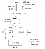
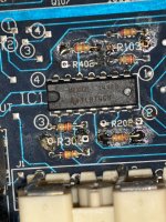
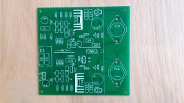
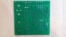
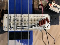
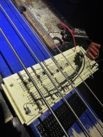
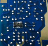
I had some of this pencile tubes 6N16B lying around for a long time and without any use, so I deceided to use them for it. I designed a single-sided board which I etched by myself. For all other parts I only used what I already had at hand: PP-caps for in- and output coupling; PPS caps for the RIAA network; generic metalfilm resistors; a 6Z4 rectifier tube and vintage VB408 voltage regulators (more on this later) -no fancy parts here.
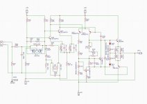
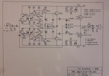
This is roughly the circuit suggested by Frank Blöhbaum; bias-current is set by R9 and by R4 for V1b.
T1 serves as a "transconductance-multiplier" for V1a whereas R5 transforms the collector-current to a voltage for the next triode V1b.
...next I changed R5 to an RIAA network:
...and that was actually it. The real circuit has of course some more parts, mainly for saftey- and protection.
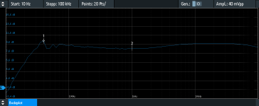
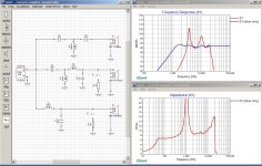
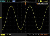
The first tests were promissing: wide bandwith (20Hz to >>100kHz) and high gain (49dB). Input resistance is ~45kOhm.
Frequency-response (the 40mV input is scaled down by the anti-RIAA by 100):
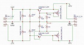
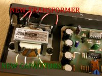
Since I only used parts I already had, in this case a 230:230V transformer, I had to get rid of some excess voltage in the PSU -and what does this more elegant than a tube rectifier?
The CCS is realised with a LM317 in a TO-92 housing; a resistor instead of the CCS will do the job as well- but I had a lot of these Vregs left.
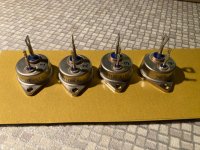
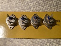
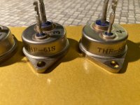
I expected this amplifier not to have good PSSR, so I put two VB408 voltage regulators, one for each channel, behind the rectifier.
Heater voltages are supplied by a separate transformer, rectified and filtered.
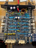
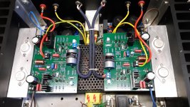
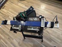
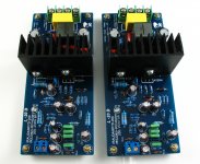
The first test-board with PSU:
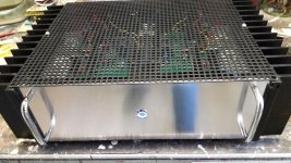
The final amplifier in a housing. The corner-elements are 3D-printed, the alu sheets are from the bin.
Protection earth and signal ground are separated by an ICL (10Ohm @ 20°C). Some rubber pads serve as provisorical feet.
I also forgot a separate grounding-connector for the tonearm, so I clamped the grounding connector from the tonearm wire under the top cover sheet (in contrast to my other phono-preamps it made a difference here when I connected it- possibly a result of the input-capacitor? My other phono-pres are DC-coupled in to out).
I was surprised by the low noise (there's no hum) and the vivid and natural sound with deep and articulate bass.
In the last years I have bulid more than 10 phono-amplifiers (with Opamps and transistors), most of them better than it's particular predecessor; the last 5 or so with LR equalization, which I found superior so far. This amplifier is something special. My latest LR-phono is a tad more detailed and neutral, but this one lives...
This was my first attempt with this topology and I found it very promising. I'm already in the process of builing the next version with noval-tubes and some other modifications.
Cheers, Boris