Hi All! I’m new here, but I posted this on Head-Fi and Audiophile Style, and I haven’t gotten much traction. I’m curious if folks here have any ideas on how to make this work.
_____
It’s 2025, people, and the world needs a plug and play, headless, “it just works,” Raspberry Pi (or other SBC) running HQPlayer Embedded locally. I know, HQPlayer is supposed to need a small nuclear reactor to crank DSD 2048 with unspeakably complex filters and noise shapers, and I am 100% for that at home, but what about on the road? Hear me out…
The Vision:
I think a lot of us have wandered into the HQPlayer conversation after encountering a product from Chord, realizing that handling of digital signals is absolutely crucial to sound quality, getting addicted to the detail and musicality, finding out about the M Scaler, seeing the price, throwing up a little, and then thinking - “there’s got to be a better way” and landing on HQPlayer. Besides giving Jussi a bit of an ulcer with constant comparisons to the M Scaler and its legendary million taps, this process has also had the side effect of Mojo / Mojo 2 ownership among a large portion of the HQPlayer audience.
The Mojo is in an interesting spot in the audio device stack. It’s certainly capable of competing with most modest to moderate desktop stacks in terms of sound quality, yet it is portable. We have seen a significant rise in quality (and prices) of high end dongles that also compete in this space. Of course, DAPs are also reaching ever loftier heights of technical prowess. We can enjoy incredibly high quality audio on the go, and now that we have heard the benefits of HQPlayer, why are we depriving our portable systems of this essential upgrade. It might have seemed crazy in the past to spend almost $300 on software to upgrade the sound of a portable system, but that’s the going price for a battery base for the Woo Audio Tube Mini, and it’s less than half of what people will pay for a Chord Poly just to act as a streaming endpoint with no upscaling at all for the Mojo.
I travel a lot for work, and when I do, it’s with an iPad and iPhone and either my Mojo 2 or Tube Mini depending on how I’m feeling before heading to the airport. I don’t have a laptop, but I do have Roon Arc with Qobuz and a bunch of DSD and Hi-Res PCM files on my Roon server with my favorites saved locally on my phone. So, HQPlayer on a laptop is not really a practical solution, and a VPN would be fine when I have a great internet connection and everything works perfectly and I don’t have to reset my desktop, but it seems janky and redundant when I’m already effortlessly playing my newest MoFi and Analogue Productions SACDs that I’ve ripped to my Roon server through Arc to my portable DACs.
All that is missing is a little box that sits between the phone / iPad and DAC and magically makes the music from Roon Arc sound even better - no screen, no settings, just switch it on, plug it in, and benefit. Think of it almost like a mini M Scaler or a mobile DDC or a Poly-ternative. It would be perfect in the hotel, at Head-Fi meetups / Can Jam, when auditioning gear at a store, and on planes - Rob Watts has said he listens to his M Scaler + TT2 on planes, which is a totally baller move that I would like to replicate at a smaller scale. There are so many situations where this would be useful, and I think it is possible now. I don’t think this is something that we will need to hassle Jussi to do. As a community, I think we can build it, grow it, evolve it, and share it.
Tools and Challenges:
Frankly, when I started looking at HQPlayer about a year ago, I just assumed that someone had already come up with an implementation like this, and you can see my confused posts on the HQPlayer settings thread from late March 2024 just assuming I was tweaking some setting wrong. After doing a bit more digging, I don’t think this has been done yet. I think the parts are all there, but we just haven’t pulled them together into a coherent package. I have enthusiasm and patience for messing around with things like this for way too long. I have a couple of Pi 4s and many of the necessary adapters, accessories, etc. to tweak and test implementations. I have been building, tweaking, and overclocking computers since about 2001, but I don’t know much about programming, formal computer science, or Linux, though I’m certainly willing to learn some bits and pieces if people can explain a problem to me like I’m five and point me in the direction of the necessary info and wind me up.
Raspberry Pi
To me, this seems like an obvious choice. It’s relatively cheap, it has strong HQPlayer support already, Pi 4 is powerful enough for most anything we would want to do with PCM, and with ultra light modulators, Pi 5 might be able to do meaningful DSD. Pi also has USB OTG support built into HQPlayer OS through its USB-C port. There are numerous HATs like Pi Juice that could be used to provide power through the GPIO pins as well as some limited battery and a separate charging port (suitable for a power bank as well).
We have Pi 4 and Pi 5 to choose from, and for a first run at this, I think we will need to pick a lane here. Open to suggestions, but Pi 4 seems like it will be the more mature system with more manageable power draw and thermals, but I could also understand if people feel that this wouldn’t be worth doing if it doesn’t do DSD, which would be more of a Pi 5 thing, if it is feasible at all at this stage.
HQPlayer OS / Embedded vs HQPlayerd
This is where I am out of my depth. I don’t feel like I have a good understanding of the options here, and I am not sure there is a single place to get a straightforward comparison of the possible implementations. This is a question for a person with significant Linux and / or HQPlayer experience I think.
I nearly have a Raspberry Pi 4 with HQPlayerOS working in this use case, but the jankiness level is extreme. It has played from my iPhone Roon Arc app > USB C OTG > Pi4 HQPE > Mojo 2 a couple of times using the USB C into the Pi4 and the USB A out and the Pi Juice HAT with or without a battery (can just be plugged into the wall for full power through its own micro USB port). It requires access to web interface to start playback from the USB port, however, and this would not be feasible for the intended use case.
I think it is reasonable to configure the settings for filters, shapers, modulators, etc. using the web interface once on a home network. It might also be nice to have a few different SD cards that can be used with different DACs, if, say you want PCM for your Mojo but an AK4499EX DAP might do better with DSD. You could just configure each installation the way you like and drop in the card that corresponds to the DAC / Dongle / DAP you want to use that day.
It is totally not reasonable for this use case to have to log into the web interface and enter a URI just to start the music playing. This seems like the biggest hurdle we face on the software side from my novice perspective. Given the level of sophistication of even relatively cheap dongles using UAC 2.0, I have to think that this problem has a solution, it just needs to be implemented.
In my vision, there is no need for a screen, options, or really any level of configuration while out and about. If we are successful in this first iteration, then I could see it expanding into something much more DAP-like. It could have a screen with options, it could replace the phone and act as a streamer, or it could replace the DAC/AMP with a fancy HAT or possibly some version of DSC-1.
3D Printing:
I’m planning to get into 3D Printing in the near future (I have a Bambu Labs A1 on the way), though I have no experience so far. My wife is extremely crafty and would be interested in helping. I already have a number of ideas for different audio-related bits and bobbles, and I could definitely see making a case for the Raspberry Pi and Mojo 2 together. This could obviously be adjusted to accommodate other dongles / portable DAC/AMPs. We could make the CAD files available for people to edit for themselves.
Future:
A couple of interesting thoughts have crossed my mind here as well. I wonder how long it will be before we have something like a Pi Zero 3 with hardware that could come close to Pi 4 performance. I also wonder if solid state cooling will make it possible to run a Pi 5 fast at relatively high power and performance in a small form-factor case (there will be new demos of solid state cooling chips at CES this year). If we get started imagining together, it’s hard to tell what awesome ideas and use cases we could come up with!
Next steps:
First and foremost, I would love to hear feedback and others’ ideas for how to proceed. Is there a possible direction or solution I haven’t thought of? Is it even remotely feasible to configure HQPlayer Embedded / OS / other version to behave in the way I’m envisioning with no need for user input after initial configuration? If so, can you do it or tell me how to do it (preferably like I’m five)?
I think we need to pick a device to be the heart of this thing and prove that the software can work. If it does, then I think we’re off to the races with testing potential accessories for power, I/O, case designs, performance / temp / battery life optimization / electromagnetic interference management / etc. (these are areas where I believe I can be of great service, more so than with the software).
This project also needs a clever name…
Thanks for reading, and I can’t wait to hear your ideas!


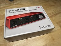
![20241117_173348[1].jpg](/community/data/attachments/1292/1292579-bcd66861214e69944f8317f6eba8c745.jpg?hash=LIAhW0d4Yt)
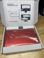
![20241118_110204[1].jpg](/community/data/attachments/1292/1292580-581e1c2c6078c3a4ec878700dd9c5908.jpg?hash=82Bl1mznOu)