Help with 15" SB Audience sub project

In 30+ years of DIY speakering, I've never considered building a sub before. A recent acquisition of a used pair of KEF LS50 Meta & a simultaneous request from my son to make him something that can give near nightclub levels of modern electronic music (with the LX521-ish clones I made him last year) is making me think about subs.

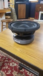
I'm considering a hifi sub with SB Audience Nero-15SW800, a pro 15" driver. Specs look great for a pro subwoofer -- Fs=31Hz, Xmax=14.27, AES power=800W. Rated 96 dB/W but this looks optimistic, tho it's definitely >90 dB, amazing for an 8 ohm model (at least in home hifi).

My ideal target is -3 dB to 30Hz, up to 110 dB@1m, capacity to run up to ~120Hz. Willing to feed it >600W.

Not sure if that's realistic.

Madisound says... "Vented box of 4.0 cubic feet with (2x) 3" vent by 6" long for a 3dB down of 35Hz. 6dB down of 28Hz". That's pretty close & room gain might bring it to my target.

The diyaudioandvideo speaker box enclosure designer says...
Butterworth B4 -
Vb = 3.22 ft3 (91.07 lts)
f3 = 36.91 Hz
fb = 36 Hz
Dv = 6 in = 15 cm
Lv = 13.75 in = 33.65 cm

https://subbox.pro/ says in a 18x18x28" box (~4 ft3), a 1.4" slot 6.2" deep and the width of the 18" face will give 36 Hz tuning.

sub1.jpg


The woofer choice is not firm, but I really like this driver, which was pointed out by Joseph Crowe. He compared it favorably with a TAD TL1601B -- a US$1750 driver-- that he used in his horn loaded bass enclosure. Solen retails the Nero-15SW800 for CA$447.

I have not ruled out other enclosure types, but 4 cubic feet is about as big as I can go. I chose ported because it's the most widely used & even tho the shallower 12 db/oct slope of a sealed box is better for deep bass, I want to keep the excursion low to ensure my son gets all the bass he wants. His room is about 14 x 22 x 10 (ceiling), with big doorways into other parts of the house. I figure ported will limit excursion down in that 30 Hz region. A sharp 24/48 dB low filter will likely be applied ~20 Hz, depending on subjective perception in actual use.

Suggestion, direction, insights about design & construction are most welcome.

EnABL-ing MAOP7

We discussed previously whether or not EnABL would improve a MAOP driver, and I volunteered my MAOP-7 to try it. Sorry, couldn't do it earlier. Preparations for winter occupied most of my time - I live in a countryside.

First, I tried to do tap test to determine optimal positions of the patterns. It didn't work - at any distance on the cone radius tap sound was the same. Tapping worked on a 4" Sony speaker with a paper cone, I could find positions where tap produced the loudest sound. I guess the MAOP cone is pretty well-damped as-is. Without tap test guidance, I decided to apply patterns 1) close to surround; 2) on former close to cone boundary, and 3) on top of the dome. See pictures for details.

The patterns were applied free-hand using extra fine Utilto acrylic paint markers, black and white. Surround pattern was applied to back side of the cone to conceal my ugly handiwork. To build up thickness (pens lay paint pretty thin), three layers were applied: black-white-black. On the cap, a single layer of white.

The difference showed on the first test record, Beatrice Rana Chopin Preludes. This is a very well recorded piano album. The second prelude is played between piano and pianissimo. Control untreated driver played soft, but with the EnABLed driver I could hear string buzz that wasn't apparent before. Those familiar with the sound of top level instruments like Steinway or Fazioli will understand what I am talking about.

Further testing is unnecessary. It worked.

Attachments

  • 20241207_150342.jpg
    20241207_150342.jpg
    268.9 KB · Views: 97
  • 20241207_150434.jpg
    20241207_150434.jpg
    226.6 KB · Views: 99
  • 20241207_150359.jpg
    20241207_150359.jpg
    104.4 KB · Views: 103

For Sale Tangband W8-740B

New in box.
I over ordered not knowing there are 2 drivers per carton.
So 4 drivers for sale as a package.

If you order 50 at PE they are $135.00 each and 90 days out.
https://www.parts-express.com/Tang-Band-W8-740P-8-Subwoofer-264-854?quantity=50

$400.00 plus shipping, payment via PP FF.

Each carton weighs 23lbs and is 20x10x7 shipping from 55373.

Attachments

  • TB Driver Small.jpg
    TB Driver Small.jpg
    459.2 KB · Views: 104

I'm a new member. Here is some background

Hi Everyone. I've been enjoying audio gear for about 50 years and over the last 5 years have been working to get more of a technical understanding of audio components. I have a pretty nice basic workshop at this point and have progressed from complete amp and preamp kits, and recapping and refurbishing some of my old gear to sourcing boards, transformers, rectifiers/regulators and then drilling and cutouts on different cases to make a few preamps and amps. It has been quite challenging without any formal training in electronics but I've learned some things are I'm beginning to make some sense of it now. Still, I'm essentially a beginner but enjoy the challenge of learning as I go.

I hope that I can learn even more by being a member of the diyAudio community. Thank you!

--Jonathan
  • Like
Reactions: mbose

Free Hypex DLCP digital preamp and electronic crossover

I have a DIY Hypex DLCP preamp and 3-way active crossover that I'd like to give away. The unit works perfectly and comes with the programming software, manual and remote control. The DLCP is meant to be the heart of a 3-way active speaker. It can also be used as a preamp with digital EQ. It is limited to 96k digital. It includes Hypex Filter Designer software to measure the frequency response of drivers and create crossover and EQ filters. You can download the spec sheet manuals at: https://hypex.nl/dlcp. I'd rather not pack and ship this guy. Local pickup in San Jose, CA preferred.
DLCP1.jpg


DLCP2.jpg


DLCP3.jpg
  • Like
Reactions: Gill.T

Meyer Sound MS818-HTS 18" Woofers

Hello all,

I have a pair (x2) of beautiful Meyer Sound MS818-HTS 18" 8-ohm Woofers that are looking of a good bass cab
I believe they are spares from a theater and appear to be unused, therefore in perfect condition
Cast frame, heavy duty accordion surround, ferrite magnet, used in several Meyer Sound subs
They are big and heavy so probably only suitable for shipping within Australia?
I'm thinking USD 600 for the pair is a fair price but open to offers

Cheers, Ralph

Meyer MS818HTS0.JPG

Meyer MS818HTS2.JPG


https://audiofile.net.au/

Mission 770 freedom V crossover upgrade.

Hi all. I'm new to this group, but it seems full of very knowledgeable people and I wonder if you'd be able to help me out? I have a pair of mission 770 freedom Mark V which I really do love. I keep on comparing them against other speakers and they keep on coming out better however looking at the crossover I see that one of the resistors has got so hot that it's melted the plastic that has attached to so I think there must be some serious need for replacing some of the components such as the resistors and capacitors. Of course these are 40 yrs old and I'm a rank amateur in recognising and decoding the codes on the components so that I can replace them. Anyone to hold my hand through this would be much appreciated. Note I have looked at other posts and there is nothing that answers my questions. . Many thanks

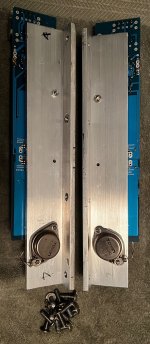
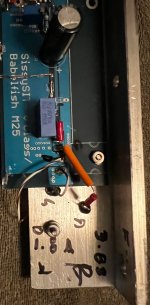
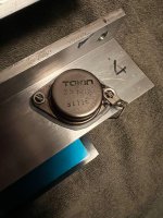
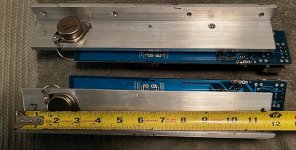
For Sale Babelfish M25, SissySIT stuffed Boards (w SIT) ready for your power supply and case

SOLD to birdbox

As the title suggests:
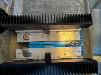
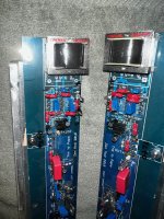
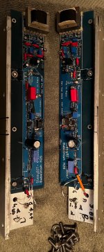
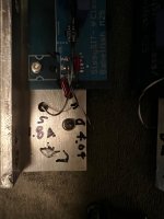
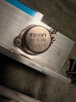
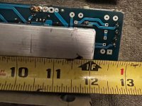
For sale, boards from Zen Mod 2018 (stuffed) with pair of 2SK180 mounted on aluminum Tee bar (12") and pair of Cinemag CMOQ-4HPC (high Nickel) transformers.
These were removed from my case as a working setup. I just have too many amps and want to try something new.
I used a 23 volt +/- DC power supply. All settings should be good to go in your new case. I cut the power wires off at the board so as not to heat the board excessively.
Asking $275 OBO plus shipping. PAYPAL friends and family
I prefer USA transactions due to weight with aluminum T bars.
Please PM with zip code and phone number so I can determine cost to ship.

Attachments

  • IMG_6916.jpg
    IMG_6916.jpg
    1.1 MB · Views: 101
  • IMG_6918.jpg
    IMG_6918.jpg
    807.9 KB · Views: 97
  • IMG_6919.jpg
    IMG_6919.jpg
    731.3 KB · Views: 89
  • IMG_6922.jpg
    IMG_6922.jpg
    602.1 KB · Views: 89
  • IMG_6923.jpg
    IMG_6923.jpg
    413.5 KB · Views: 89
  • IMG_6924.jpg
    IMG_6924.jpg
    364.5 KB · Views: 90
  • IMG_6925.jpg
    IMG_6925.jpg
    496.8 KB · Views: 93
  • IMG_6926.jpg
    IMG_6926.jpg
    501.4 KB · Views: 79
  • IMG_6927.jpg
    IMG_6927.jpg
    711.3 KB · Views: 76
  • IMG_6928.jpg
    IMG_6928.jpg
    349.7 KB · Views: 94

Looking for home audio DSP with extended range

Hello,

I am new here and fairly new on my journey on building a high quality speaker project. I am a residential architect that recently rekindled my love for great sound and I am diving into the world of product design with my first attempt at designing an auditorily and visually beautiful enclosure. Before I begin ordering drivers and start the actual build, I am trying to select components that will serve as a great foundation for driving various iterations as I go.

My end goal is to build a pair of 3-way speakers for audiophile grade music listening with a frequency range between slightly below 20Hz to 40khz. I would like to drive each tweeter, mid-range woofer and subwoofer individually with either a single 6 channel amp or most likely discrete amps for each pair depending on the power demands of the individual drivers.

I found various drivers (from SEAS, Scan-Speak, Mark Audio and Tang Band)

One possible pairing might be:
-Scanspeak Illuminator D3004/6640-00 1" Tweeter Beryllium Dome - 4 Ohms
-Scanspeak Illuminator 12MU/4731T-00 4.5" Midrange - 4 Ohms
-ScanSpeak Revelator 26W/4867T 10" Woofer Black Aluminum Cone, 4 Ohms

Another might be:
-SEAS E0121-04/06 C16NX001/X - 4 Ohms - 100W (coaxial mid and tweeter)
-SEAS XM001-04 L26ROY - 4 Ohms - 250 Watts

For amplifiers, Emotiva seems to fall within my budget and criteria. (open to suggestions on this and everything else)
  • For Tweeter and Midrange woffer: Emotiva BasX A4 Four-Channel Power Amplifier 130 watts per channel - 4 channel @ 4 Ohms ($549)
  • For Subwoofer: Emotiva BasX A2 Stereo Amplifier 250 watts per channel - 2 channel @ 4 Ohms ($579)

Now I am on the hunt for a pre-amp DSP with at least 6 channel output capable of the wide frequency range I am looking for. It would be great if it also includes room correction features.

So far I found the miniDSP Flex Eight ($549) and the Octo dac8 Pro ($1,300+/-). I might be wrong, but I believe those both are limited to between 20Hz and 20kHz.

Being new at this, I am very open to suggestions, tips and tricks on the best practices for equipment matching. In my case I'd like the dsp/amp setup to be somewhat flexible for various driver configurations I might try along the way. As for budget, I would like to keep it reasonable, but open to spend a little more for valuable features and high quality.

Thanks and looking forward to the journey!
-Chris

Aleph J - intermittent static in one channel

The last week or so I’ve been getting an intermittent static in one channel of my Aleph J. It comes and goes. Sometimes quite loud then later almost disappears. Amp is four years old and has been very reliable and basically dead quiet until now. I opened it up and don’t see any loose connections? This is a dual mono amp with two separate power supplies in one chassis if that’s relevant.

Heatsink power dissipation

I got pretty stuck on this.
Managed to calculate the power dissipation in the circuit and came to a thermal resistance figure (C/W).

Now wtf to do with the C/W unit?
Isn't there some practical way to estimate heatsink dimensions by the power dissipation?

F.ex.
  • a heatsink for 4W power dissipation, no thermal pad
  • a heatsink for 20W dissipation, with thermal pad

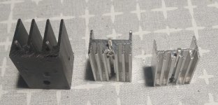
Here are some heatsinks at home:
20241211_190835.jpg
25 х16.5 х16 mm - black one
20.5 х15 х10.5 mm - mid
20 х14.5 х9.5 mm - leftmost

Would the black one handle 4W and how much the smaller ones would handle?

Another one - 50 x124 x35 mm
8341_img_2.jpg
How much power dissipation for this one?

Regards - Emil 🙂

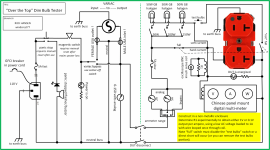
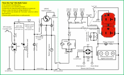
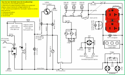
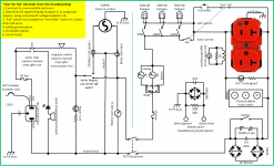
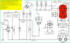
Over the top dim bulb tester, improvements

I will keep the latest schema in post #1, ignore any others in threads I have made mistakes...

I do a lot of breadboarding for fun. Currently I've just been running my Variac into a chosen step up transformer, then into a LCLCLC (secondary fused) 200ma chokes, pi filter to get 0-n DC volts choke regulated but pretty damn clean and stiff. I'm very cautious about handling, one hand in pocket, shoes on, standing at bench not sitting, and I wear tight disposible nitrile gloves as a last defense, and I set my personal limit at 500 VDC (for now) etc. But I thought I can make things even safer by improving the mains supply chain... I'm thinking of more fuses, current limiting (dim bulb), an always-present analog AC ammeter and AC voltmeter, more indicator lights of charged connection points, adding a twist-reset "panic" shut down switch, maybe a red beacon light bolted near bench indicating mains is on, etc. On the DC side I want to make a cap discharging probe with led and resistor that I can quickly use to reset things.

Design with the help of posters in the thread:

OverTheTopDimBulbTester.png

Attachments

  • OverTheTopDimBulbTester.png
    OverTheTopDimBulbTester.png
    382.4 KB · Views: 604
  • OverTheTopDimBulbTester.png
    OverTheTopDimBulbTester.png
    499.1 KB · Views: 245
  • OverTheTopDimBulbTester.png
    OverTheTopDimBulbTester.png
    462 KB · Views: 873
  • OverTheTopDimBulbTester.png
    OverTheTopDimBulbTester.png
    462 KB · Views: 386
  • OverTheTopDimBulbTester.png
    OverTheTopDimBulbTester.png
    465.2 KB · Views: 357

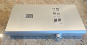
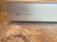
For Sale Schiit Freya S and Gungnir Multibit DAC

I have for sale two nice Schiit pieces. The Freya S is a really nice quiet balanced preamp w/ remote. The DAC sounds great. Both in near mint condition with the exception of the DAC which has a bent BNC connector. If BNC is critical to you...you could replace or send back to Schiit for repair. I ran SPIDF with this and never cared to do anything about the connector. The DAC has the standard USB card. $500 for the pre-amp and $700 for the DAC OBO shipping included CONUS. Only reason I'm selling is because I moved to a miniDSP system and no longer can use an external pre/DAC. Feel free to IM with questions.


Dac 1.jpgDac 2.jpgDAC 3.jpgPre Amp 1.jpgPre Amp 2.jpgPre Amp 3.jpg

Complementary Power MOSFETs

The truely complementary pair of MOSFETs 2SK1530 / 2SJ201 is now unobtanium.
Even our own stock has been depleted.
The search for alternatives has not stopped, however.

We have previously had good experience with the Fairchild FQA9P25.
https://www.diyaudio.com/forums/solid-state/343164-udness-dont-semisouths.html
So we have been looking for some time for a compatible N device.
https://www.diyaudio.com/forums/pass-labs/369546-f5-2sk1530-2sj201-post6577901.html

Finally I got one sample of each and curve traced them.
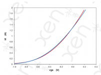
Here is the result.
The NMOS has a Vgs pf 5.5V at 1.3A, and a Yfs of 3S.
The PMOS has a Vgs of 5.2V at 1.3A, and a Yfs of 2.7S.

In the graph below, the Vgs is manually aligned to 0V at 1.3A for ease of comparison.
As this is only one single sample, it is difficult to tell whether the difference is statistical or systematic.
But there is a reasonable chance that even better NP match can be found in a larger batch.


Patrick

.

Attachments

  • FQA Complementary Public 211009.png
    FQA Complementary Public 211009.png
    61.2 KB · Views: 1,277
  • Like
Reactions: pbilous

Does anyone have a circuit diagram for a WEAH D222 Crossover?

I recently acquired a pair of Solavox TK30 speakers and have been advised to replace the capacitor that provides the bass-roll of for tweeter protection. I also wanted to put proper terminal binding posts in each speaker to replace the captive wires.

I have acquired a pair of WEAH D222 crossovers which are integrated with the terminal block so seem to include the necessary components, sporting a hefty inductor as well as various capacitors and resistors. My guess is this is overproduction of a crossover aimed at car loudspeaker systems as there seem to be lots of ads on the internet for this.
I have included a photo and I have derived a circuit diagram based on continuity tests, but I'm puzzled by the 2 white components ( blue on my crossovers) and the yellow component. They appear to be in series with the larger tweeter roll-off capacitor at the top of the photo, but I don't understand the function - some sort of tweeter protection I imagine. Does anyone have an official circuit diagram for this crossover ? I'll post my attempt if required but it would be much easier if someone actually has the diagram, then I can decide if I want all these components modifying the signal to the tweeter.
Crossover 80W.jpg
.

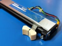
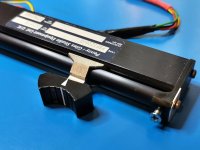
For Sale Penny & Giles Conductive Plastic Faders

Hello all,

I have a number of Penny & Giles Conductive Plastic Faders available for sale

3x different types:
-10k mono white knob (PGF3220): USD 30 for a pair (x2)
-10k mono black knob (PGF3220D): USD 30 for a pair (x2)
-5k stereo (D21009): USD 40 for a pair (x2)

All are in good to very good condition and most have knobs and screws included

More details at https://reverb.com/shop/audiofile

Cheers, Ralph

https://audiofile.net.au/

Attachments

  • 3220-3a.jpg
    3220-3a.jpg
    187.3 KB · Views: 52
  • 3220D-3a.jpg
    3220D-3a.jpg
    182.8 KB · Views: 52
  • D21009-2a.jpg
    D21009-2a.jpg
    252.4 KB · Views: 47

Audiolab 8000C phono connection question

My father's ancient Cambridge Audio integrated has died, so I thought I'd give him a spare amp from my hoard. He needs input switching and a phono input, so it will have to be an old 8000C I bought from eBay years ago, without a manual.

The phono inputs aren't quite what I expect - there are sockets for 'Load' under Phono MM and well as 'In'.

What does 'Load' do?

phono.jpg

freeDSP-aurora - DSP with 8 I/Os, USB Audio, S/P-DIF, ADAT, Bluetooth and Wifi contro

Hello,

I would like to introduce my newest design of the freeDSP family: freeDSP-aurora. It was already introduced in the freeDSP main thread, but there the idea came up to open a new thread only for freeDSP-aurora.

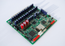
freeDSP-aurora is a one board DSP solution. It all started with the development of a DSP powered subwoofer amplifier. Once the prototype of this amplifier was presented on the German forum diy-hifi.forum.de a fruitful discussion about additional features and ideas started. After two years of development freeDSP-aurora is the distillation of the best ideas.
So here are the features of the board:

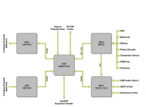
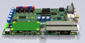
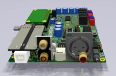
  • Analog Devices ADAU1452, 294.912 MHz, 32-bit SigmaDSP, 6144 SIMD instructions per sample @ 48kHz fs, 40kWords of data RAM, 800ms digital audio delay pool @ 48kHz fs, eight stereo ASRCs with 139dB DNR
  • XMOS XE216-512-TQ128 for multichannel bidirectional audio streaming
  • ESP32 for WiFi or Bluetooth control
  • AKM AK4458 32bit-DAC
  • AKM AK5558 32bit-ADC
  • Supporting sample rates between 44.1kHz and 192kHz
  • 8 analog balanced input channels, +6dBu
  • 8 analog balanced output channels, +6dBu
  • S/P-DIF input and output
  • ADAT input and output
  • Wordclock input and output
  • Support for display, rotary encoder, volume potentiometer, temperature sensor, PWM controlled fan, IR sensor
  • One freeDSP expansion header
  • USB Audio Class 2 Bidirectional streaming with 8 channels in and 8 channels out, full-duplex. Works with ASIO driver under Windows 10 and driverless under macOS and Linux.
  • Board dimensions: 100mm x 100mm

To make using as easy as possible I wrote my own app that controls the DSP via Bluetooth. The app runs on macOS, Windows or iOS. Thanks to the ESP32 framework Wifi instead of Bluetooth is an option.
The features of the DSP depend on the DSP firmware. Therefore, I have made a first DSP firmware with the following features per channel.
  • Input select
  • High pass up to fourth order (Bessel, Butterworth, Linkwitz-Riley)
  • Low shelving
  • 10 parametric EQs
  • High shelving
  • Low pass up to fourth order (Bessel, Butterworth, Linkwitz-Riley)
  • Frequency depending phase shift (allpass)
  • Phase inversion
  • Delay 100ms
  • Gain
It supports 8 channels in and out.
This feature list is only a first step. It can be extended in the future, e.g. FIR-Filters are already on the ToDo list.

Like any other freeDSP the project is licensed under an open source license. Thus, everybody is invited to modify or contribute to this project. You can even download everything and build as many freeDSPs as you want. You can find everything on freeDSP | An Open-Source Low-Budget Audio DSP and in the git repository GitHub - freeDSP/freeDSP-aurora: freeDSP ADAU1452 with 8 analog input, 8 analog outputs, S/P-DIF I/O, ADAT I/O, USB Audio Class2, WiFi, Bluetooth

Well, for freeDSP-aurora a new idea came up: A kickstarter campaign has been launched. This campaign shall help to make boards available for those who do not want to order empty PCBs and solder the SMD stuff and do all the firmware flashing. The kickstarter campaign can be found here:
freeDSP-aurora DSP by auverdion — Kickstarter

I am sure you will have a lot of questions because the board has so many features. Please feel free, to ask me!

Raphael

Attachments

  • a0eae6529aa63742db253cbade505578_original.png
    a0eae6529aa63742db253cbade505578_original.png
    494.1 KB · Views: 7,509
  • 6b202550d548f147f75bdbb9adb6701c_original.png
    6b202550d548f147f75bdbb9adb6701c_original.png
    85.2 KB · Views: 7,500
  • bd2b2def632df9ec4a0de80b0380038d_original.png
    bd2b2def632df9ec4a0de80b0380038d_original.png
    169.8 KB · Views: 7,373
  • Thank You
Reactions: YashN

For Sale F5 Turbo PCBs and Transistors x2

Ehem, missed one box of goodies.

So last but not least:

2x F-5T V1/2 Transistor Kit F-5T V1/2 Transistor Kit $79.00 each
2x F-5T F-5T $49.00 each
1x Matched JFETs - Toshiba 2SK170/2SJ74 Octet 8-11mA Matched JFETs Toshiba 2SK170/2SJ74 Octet 8-11mA $100.00

(original prices without tax and shipping)

Selling either 1 set of PCB transistors and 4 JFETs or the whole bunch, 1 set 150 Euros plus shipping or both for 275 Euros plus shipping from Germany.

Attachments

  • F5T.jpg
    F5T.jpg
    553.2 KB · Views: 100

FreeDSP INTEGRA

Hello Guys,

Now I am planning the DSP-integrated Power Amplifier Board Project.
Current ideas are two variations ...
  • FreeDSP INTEGRA Duo (ADAU1466 + TAS6422) Stereo Speaker Output
  • FreeDSP INTEGRA Quad (ADAU1466 + TAS6424) 4ch Speaker Output
For starters, now I'm working on a 2ch version prototype design. The intention was to install the Full-Range/2-way boombox enclosure.
But this can be a single-board solution for desktop audio systems...

PCB-Plot_BottomDiemensions_0v3.jpg
PCB-Plot_BottomDiemensions_0v3_Rear.jpgPCB-Plot_BottomDiemensions_0v3_Side.jpg

Input
  • RCA Analog
  • Optical S/PDIF
  • Coax S/PDIF or AES/EBU
  • USB (Amanero Combo384)
  • Raspberry-pi Zero W/2W
Control
  • AUX POT x1 (for DSP)
  • Source Selector (TBD)
  • Rotary Encoder x1 (for Power-Amp)
  • A push-button or clickable Rotary Encoder
  • 3digits LED Display
  • PIC16F18346 MPU
Output
  • Speaker Output x2 (Duo), x4(Quad)
  • Optical S/PDIF
Power Supply
  • 2.5mm Center 5.5mm Sleeve Wall Power Adaptor or 24V 4A PSU
  • Screw Terminal for Power Switch


CyberPit

Wire Bryston tranformers in series for 230V?

I have a Bryston 2B-LP that I bought new in the US in 1987. I've moved overseas and back with it a couple of times. While using it overseas, I always had it plugged in to a step-down transformer.

It recently occurred to me that I might be able to convert it for 230V by rewiring its two transformer primaries in series. That's sort of what restrappable transformers do, except, here, there are two separate cores, so, if the current draw of one channel was significantly higher, it would probably tend to sag more, since the other transformer would have more back EMF and be dropping more of the supply voltage. Is that a real concern, or does this plan sound reasonable? BTW it ran fine for years off of 50Hz 120V, so I'm not too concerned about the frequency.

Dorati NOS DAC kits

Orders now are open on Dorati NOS DAC kits - PM me and be sure to include your payment method and location so I can quote you inclusive of fees and shipping. Dorati offers a sound quality upgrade over its predecessor 'Kubelik' but retains the same physical footprint of 81mm * 50mm, slightly smaller than a credit card; the maximum height is 24mm. The design is non-oversampling (i.e. there's no digital filter on-board) uses passive I/V and has a discrete output stage. What sets it apart from typical NOS DACs is the use of an LC filter prior to the active stages. The input format is I2S (three signal wire) at 44k1/16bits. BCK can be 1.4 or 2.8MHz, no MCK is required. Output is CD standard 2VRMS and headphones at 300ohm impedance and above can be directly driven. Power supply requirement is a single 12-15V rail at 150mA max. There's a digital invert function, selectable by a 0R resistor. Schematic may be found here : Dorati schematic updated 6.23
Dorati can be used in a pair of boards to create a balanced output DAC. To achieve this you'll also need an I2S splitter board which is sold separately. The splitter changes the normal L,R stereo configuration of I2S into two outputs: L+,L- and R+,R-.

Preferred payment method is via Wise which typically adds a 2% fee. Our receiving currency is CNY, alternatively USD or Euro. PayPal may also be used, in USD but will attract higher fees, about 6%.

Price for a Dorati kit : 168RMB (~$25)
I2S splitter board to create balanced output DAC : 90RMB

Shipping is in addition and depends on your location and speed of service. Courier (FedEx, TNT, DHL) typically takes 8 - 10 days and e-packet four to eight weeks. Not all locations can be serviced by e-packet though.

FAQs

What else is needed to turn the built up Dorati kit into a fully operational DAC?

First you'll need a well regulated low noise power supply of 12 - 15V rated at 150mA or higher. An LM317-based board set to the correct voltage will suffice if you already have an unregulated supply (like a typical wall-wart). I don't recommend switching supplies due to issues with common-mode noise, its very hard to filter out. This dis-recommendation though only applies if you're building a stand-alone DAC. If you are building the Dorati into a system with the amps in the same box then switching supplies are perfectly fine but I would then recommend an LC filter to reduce the switcher's output ripple, a direct connection is likely to reduce SQ. We can supply an LM317-based board with either DC (for unregulated DC) or AC (for a transformer) input option. LC filters for SMPSUs are on the drawing board as I write this, best enquire if they've become available.

Second you may need a digital interface card. I say 'may' because some digital sources produce I2S directly (like Raspberry Pi, many dedicated SDcard players) but most sources will either output USB (like a PC or laptop) or S/PDIF coax (a CD or DVD player) or Toslink. We can supply a card for interfacing one (or more) of those sources to Dorati's I2S input. A CM6631A-based card for USB input is the premium choice as it operates under 'async USB' which is the lowest jitter. A mid-range alternative is an interface based on an STM32F4 microcontroller - while still low jitter, its output is not as clean on start/stopping as with CM6631A. TE7022 is another suitable USB controller chip in the mid-range bracket. In the bargain basement dept are the interfaces based on 'adaptive USB' such as CM108 and PCM270X.

There's an advantage in going for a USB interface that operates on full-speed USB (12Mbits) rather than high-speed (480Mbits). That is - you can buy a cheap isolator device to use with it and isolation from your PC's common-mode noise is most definitely worth having from a SQ point of view. 480Mbit isolators have recently become available but are much more expensive (price ratio in the region of 10:1 compared to 12Mbits). For my DACs I have come to the conclusion that isolation is more valuable than ultimate lowest jitter. Full-speed USB interfaces only go up to 96k sample rate so if you're someone who needs 192k then look out for a high-speed isolator.

The S/PDIF board we recommend handles both coax (two inputs) and Toslink. Further, it has a switched I2S input - this is useful to accept an I2S stream from a separate USB interface card to facilitate a USB input. A single pole switch acts as source selector, cycling through the four sources. An OLED screen is an option to indicate the selected input. If your DAC supply is 12V, you can directly power this card from the same supply as you use to feed the DAC. The simple coax/Toslink board needs a regulated 5V PSU which can be implemented via a regulator from the DAC supply.

Third you'll be wanting some output sockets, typically RCAs so you can connect your finished DAC to your amp or preamp. Or if you're feeding high impedance HPs, a 6.3mm (or 3.5mm) TRS socket. We can supply these. We also have a PCB for mounting a pair of RCAs which makes connection a little easier.

Lastly, and this is obviously optional for a DIYer, is a case. We haven't supplied cases in the past because they're so heavy (i.e. expensive to ship).

Whilst these links all worked when I posted, Ali links go stale very quickly so beware. CM6631A is rapidly becoming unobtainium, we couldn't find a single Taobao seller with stock :

USB CM6631A card examples : Aliexpress CM6631A USB-I2S
USB STM32 card example : Aliexpress STM32USB card
USB TE7022 card example : Aliexpress TE7022 USB interface
USB PCM270X card example : Aliexpress PCM2706 USB interface
USB full-speed isolator example : Aliexpress USB full-speed isolator
USB high-speed isolator example : Aliexpress USB high-speed isolator
Multi-input S/PDIF card : Aliexpress S/PDIF Toslink I2S switcher
Coax/Toslink S/PDIF card : Aliexpress DIR9001 S/PDIF receiver

Do I need special tools to build and test my Dorati kit?

You'll need some fine diameter solder (0.3mm is recommended), a temperature controlled soldering iron with a fine bit and a pair of tweezers. A magnifier comes in very handy but that depends on your eyesight. Desoldering braid is helpful for correcting mistakes. If you've never soldered SMD before then maybe Dorati will be too challenging for a first project as there are around a hundred parts. However none of them are microscopic (the smallest is 0805) and none of the ICs has pins closer together than 1.27mm. For testing you'll need a DMM (digital multimeter).


What's supplied in the kit?

There's a picture directly below of the contents (to be added) : the bare PCB plus all the components that mount on it (resistors, caps, inductors, LED, ICs etc.). Given that 0805 sized components are incredibly easy to lose, we include a spare or two for each value. Input, output and power are supplied via 4pin Molex-style headers, we supply the mating half with crimped wires to these too.


What, if anything, is unique about Dorati's design?

Commercial NOS DACs typically have minimal filtering after the DAC chip itself. Dorati has two kinds of filters resulting in a 5th order overall lowpass response - a 3rd order passive filter prior to I/V and a 2nd order active filter afterwards. The passive filter prior to any active stage improves subjective dynamics - it means the I/V buffer no longer 'sees' a step waveform out of the DAC chip, rather a continuous signal. The active filter provides 'NOS droop' compensation - meaning you get a flat frequency response to around 17kHz whereas a typical (not every) NOS DAC has roll-off approaching 3dB by 20kHz. No opamps are used, the analog signal processing stages are all discrete transistors. Dorati's DAC chips are 'multibit' but they're not strictly speaking 'R2R' as internally they use no resistors. Instead capacitors are used as elements in the DAC which have their charge constantly refreshed (similar to the DRAM in your computer) to compensate for any drift.


Kit_contents_20220609100425.jpg


Dorati Soldering Guide rev.jpg

Bryston 4B clone by Across Audio

Hello, I just had a problem today with the Across Audio by Chywen Bryston 4b clone boards.. I already done this clone a few times in the past (4B sst clone from Across Audio by Chywen Rev5) in the past and it work fine. But recently I've burn three boards back to back when trying to adjust bias to 20mv on R45. It start to burn when reaching about 10 mv. All the positive ramp destroyed... Did somebody find the solution or the cause of this problem ?
I saw that somebody that had the same problem in a post. (Fetamp)
Thanks

Rotel RTX-1058 MCU keeps DSP in reset

Hey guys,

I would appreciate some ideas based on your experience.
I am playing now with Rotel RSX-1058. There is no sound coming out of this receiver.
1) It powers up, there is a working communication between the main MCU and the front panel MCU as well as with the volume control & input selection ICs (I verified that they work)
2) The MCU keeps the output stage of the preamp in mute
3) The MCU keeps the DSP in reset state, therefore the sound goes through (if we forget mute=on) only in 'Bypass' mode, where the DSP is not used.
4) All the supplies seem OK
5) Both the MCU and the DSP oscillators are working fine

It's not hugely common receiver but based on your experience with perhaps some other devices - any ideas what typically goes wrong?

1734027537231.png

1734027543223.png


Thanks!

Want to build a single input line level valve pre … suggestions please

Hi, I want to build a high quality single input line level valve pre to partner my quad 303 amps.

I've built elekit kits before which i really like, but they only offer a pre with included phono stage etc which i don't need.

If they built a cheaper single or double input pre without phono i would buy it.

Are there any tried and tested simple designs or kits that would cover what i am after?

Thanks for any suggestions.

NAD 304 integrated amp one channel fading problem

I have an old, old NAD 304 integrated amp which I bought on my grad student budget years ago and guess what, I am still using it with a NAD 512 CD player.

A while ago the 304 started loosing signal at low levels. It fades one channel at a time, at first it was just the left channel, now it's both. The fading in two channels isn't simultaneous. It occurs more often after a few minutes of playing, rather than when the amp's just turned on.

Sometimes I hear intermittent problem that sounds like a bad wire contact, i.e. "scratchy".

Checked all wire connections, headphone output doesn't have the same problem. What could it be and what should I check/replace?

X-Statik is this a good buy @ $399. Pair kit ?

I seen this today on YouTube advertised by GR research

YouTube

It will be my first open baffle build I’ve been curious about one and for the price as a starter kit it seem too good to pass up. My last speaker I built was the BK 20 Fostek package kit I built for my ACA. That was kind of complex folded horn speaker to build took about 100 hours from start to finish.

The X-Statik looks like a simple easy inexpensive build minimum woodworking skill easy finishing. I keep having to put off my alpha J build but I was thinking of using the speakers with the Alpha J.

I used the search tool bar to see if I could find a thread on “ X-Statik “ nothing turned up. Does this mean I use the wrong search term ? Or the speaker wasn’t good enough to make it on DIY Audio Forms ?.

Anybody with experience please chime in and tell me what I’m in for when I complete this project will it be a keeper or give away as a gift ?.

Mr. Hood's Wild Ride: A variation on the JLH symmetrical headphone amplifier

I've been working on a variation of the JLH symmetric headphone amplifier that is designed to address one of its original problems, which is the relatively large values of emitter resistors needed to get the auto-bias circuitry working. The thought occurred to me that the emitter resistor values could be greatly reduced if an additional current was extracted/injected from/into the base connection(s) of the current-regulating transistors. This would, in essence, add an offset to the base voltage so the output transistors' emitter resistors could be reduced in value.

First pass results (i.e., not worrying about drift due to temperature variations) looked pretty good but the circuit's phase margin wasn't very good. The JLH design is interesting because if you place capacitors between the output node and the input transistors' emitter you get something like this:

1733972806304.png


Not shown: the version here is using .5 ohm resistors on the output transistor's emitters, much smaller than the original JLH design..

Given the phase response plot now the subject line of my post should be clear. Feed-forward, pole-zero, however you want to classify it, those driver transistors plus the capacitors work a treat.

For a 1KHz input, a 0 dB fundamental on this circuit's output has a 2nd harmonic level that's about 120dB down from the fundamental. Not surprising, considering the high OLG of the OPA1656. I'm pretty happy that the amp is stable despite the huge overall gain. At least in simulation. The output transistors' idle current is about 140mA for that result. The rails are +/-15V

Here's a screenshot with the AC feedback loop restored:
1733973993929.png

Its bandwidth is WAY too high for my taste -- it's just asking for oscillation problems due to external parasitic coupling. But that's easy enough to address.

Just to repeat, I haven't checked to see how this approach works over temperature. The bias-control loop gain is lower compared to the original JLH design (due to the lower Re) so I certainly don't expect it to be better. But, given the fact that the bias control transistors' input dynamic resistance has to be the same as in the original JLH design (since their emitter currents are the same), maybe not enough of a difference to matter.

These are all simulations so real-world results will almost certainly be worse. However, I'm encouraged because the (simulated) transistors on the + and - sides are different in terms of device parameters, yet producing that level of distortion.

I have to say that I'm not all that crazy regarding the way the driver transistors are operated (w/regard to their emitter resistors' load voltages). It's a way to ensure relatively poor PSRR. There are relatively easy ways to address it, and I have already designed/built a variation on the original JLH HA that does just that -- using +/- 4V voltage regulators.
  • Like
Reactions: hbtaudio

The Magic of the TDA1541 Chip

A few year's ago I learned all about the magic sound of the TDA 1541a Chip. As a result I purchased a Marantz PM75 amplifier as I needed an amp. But this was one of few machines at that time ( circa 1989/90 ) which has a DAC. And that DAC contains a Silver Crown TDA1541 chip. It sounds really good and I have since had all the capacitors replaced with Kemit ones. To my mind it is underrated and given that chip it is very good value for money to buy second hand.

Fast forward and I decided to upgrade my DAC. I was going down the Chord route (having also got a Hugo2) , but I had a epiphany moment when I decided to stick to old fashioned multibit technology and so decided to purchase a Marantz DAC ie D12, Project D1 or a CDA 94. The latter came up recently for purchase , which had been upgraded with black gate capacitors and better opamps. It does sound fantastic. There is a depth and holographic feel to the bass that is very appealing to hear.

I also wanted to upgrade the TDA1541A chip and have been successful ...... and I have a simple "technical" question in that regard to ask here.

Hey everyone, Thank your for accepting me here, Vintage console enthusiast here with a strange transistor project

Hey thanks for membership and for running this community, i look forward to share and develop knowledge.
Iam a big fan of the old transistor based consoles especially Neve 80 series consoles and the sound of them, I have nerded out on designing my own modules and now I want to take it a little further and use some of my old 1:12 transformers, to make a mic preamp. but with a transistor amp.
Iam looking for transistor based schematics for mic preamp that can use a 1:12 winding input transformer. If it has ever been made. I know a 1:12 ratio winding would be made for tube amps. But I wonder if anyone back in the days 60’S/70’S made any mic pres in consoles for that type of transformer, that was transistor based. Or also someone nowadays who made it would be of interest.
Let me hear if you heard about such thing or what your thoughts are on the idea.

Kind regards Bob

Pitfalls of AB testing

The pitfalls of AB testing are centered around how our brain works. During the normal day to day operation of the brain it has to map stimuli to a labeled branch of knowledge that means it collapses similar branches to one branch. If it has already heard a sound and then hears a distorted version of that sound it will map the distorted sound to the cleaner sound. That means when AB testing amplifiers that are different, the difference may only be heard the first time. On the second run the amplifiers will sound similar on the same sound track. Does that mean AB testing is impossible and unnecessary? As can be seen in these results here, these amplifiers are different in performance but the brain will correct up to 15% error so that they sound similar, the more correction applied the more pleasant as the brain is replaying the recorded familiar sound rather than the live amplifier sound.
  • Like
Reactions: head_unit

Case for Ian Canada streamer

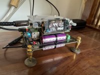
I assembled this Ian Canada streamer - the flagship compact #93B. It's come together very well - super easy to put together and sounds absolutely divine in my chain. However, it does look like a Mars lander - which I don't mind, but my family is not a fan of (the kit is in my living room), and I do worry about electrocuting some curious visitor who starts poking the super-caps.

Looking for experiences and advice on putting this in a case. One option would be to just build or buy a case into which this can go as it is - as a vertical stack. The other option would be to flatten it and put some of the boards across with ribbons connecting the GPIOs. Am ok with the mains brick outside - just need the main stack inside the case.

If anyone has built a 3D printed case for the whole stack, would love to get the designs ... or other ideas also welcome.

Attachments

  • IMG_7670.jpg
    IMG_7670.jpg
    401.2 KB · Views: 257

Comparison test DATS vs DATS+REW . Are the values at the left part of the chart OK? or caused by see INFO...

A 2.5 way basreflex loudspeaker floorstander with crossover was tested.

Multiple measurements are consistent and only differ at first impedance peak. 1 Ohm difference. ..Allways... what does this mean? Resister measurements outcomes between the 2 measure methods are the same.
Resister measurements that were done showed expected values and are within range for both methods.

Comparison measurement DATSv3
versus DATSv3 + REW

DATSv3 + REW Red
DATSv3 Purple

1732928666079.png

In REW all values except “the leads resitance value” for the impedance setup were take from the manual DATv3 on a Mac written by olen.

10kΩ for the Rsense value. (based on the value of output resistor) Don’t know my Dats R value

Set Rsense = 10kΩ


100kΩ for Rin (where is this value derived from?)

10mΩ for Rleads. I used 0.7399 Ohm Messured earlier with dats sofware.

For the reference cal I used a 4.952 ohm resistor..


-- INFO -- My version of the DATSv3 is different from olen’s...See earlier post with picture...If my dats series output resistor value differs say 2000 Ohm from the 10000 in olens Manual could that alter the reponse, and then ONLY doing so in the left part of the graph we are seeing?

Thanks I appreciate your input and thoughts..


OS on laptop, Manjaro Linux with Wine installed....Linux version of REW 5.31.3 installed
install
DATS_V3_setup.exe installed with wine installer. (right click install with Wine windows program Loader)
Installation path: home/.wine/drive_c/Program Files/
Open console and type winecfg hit ENTER
In Wine configuration window that pops up click Add application. Go to c/Program Files/DATSV3/ and select en add DATS.exe
In Wine configuration window select the just added DATS.exe and click audio at top window
I chose windows version 7 but other OS may work.
1732929332275.png
1732929392080.png

For the input and output device now there’s the just installed PCM2900C Audio CODEC Analog stereo option to choose. The rest i left at “System default” cause other settings also didn’t add any specific in and outputs. In other words I CAN NOT CHOOSE “SPEAKER” OR “LINE IN” like olen could in the manual DATSv3 on a MAC.

Also in “PulseAudio Volume Control” I chose PCM2900C Audio CODEC profile: analog stereo Duplex
1732929679256.png


When in REW ...for input and output device same CODEC is chosen...in and output were left to default
No option to CHOOSE “SPEAKER” OR “LINE IN” I think I have might have to edit some settings in Manjaro or ad pipewire or jack to route audio ins and outs...If you guys think the measurement is ok I leave it as it is for now.
have a good weekend

Want to power portion on of Marantz amplifier circuit with power supply, but want to avoid damaging my power supply

Marantz 300DC. I have one of these amplifiers and inside the amplifier is a small power transformer mounted in the front. The supplies voltage to these really small power supplies, one power supply for each channel mounted up towards the front.

IMG_4711.jpeg

IMG_4712.jpeg


These little power supplies provide a +/- 70vdc to the biasing circuit of each channel. I would imagine the current draw is pretty low. I made some corrections that were made by somebody that worked on it (no idea who did the work) and on power up noticed that the small transformer got pretty warm. Warm enough that the primary winding is now open.

IMG_4709.jpeg


I’m on the search for a transformer, but before I install a new transformer, I want to see what is going on. I intended to hook up a power supply to the amplifier channel so that I can see how much current is being drawn and make sure I get the circuit working otherwise. That way when I put the new transformer in, it’s good to go. It would be nice to see how much current is being drawn so that I might size the new transformer.

IMG_4710.jpeg


This is the amplifier circuit. You can see the +70 V goes towards the top feeding R723, R724, etc. The -70 V is towards the bottom feeding the collector of Q706, R729, etc.

I got it all hooked up as I was wanting to, and powered up the amplifier on a dim bulb tester. The bulbs stayed bright and I heard a “whirring” noise coming from the inside of the power supply. I immediately turned the power off and checked over things and nothing looked damaged at all. I was curious what the behavior was about. I found that the power supply outputs are shorted when they are turned off. I am seeing about 16 ohms across the outputs. Once I turn the power supply channel on the short goes away it course.
IMG_4708.jpeg


I am guessing this is the source of my problem. I thought I would come here for advice before going at it again. I’d really like to not damage this power supply nor the amplifie lol.

The next go, having everything hooked up I’m guessing I should have the +/-70 V turned on before powering up the amplifier? Obviously, they normally turn on at the same time when you’re using the original transformer inside of the amp.

Another thought I had was maybe wiring a diode in series, maybe a 1N4004 or 1N5404. Something to eliminate the short that the amplifier sees. I checked for backfeeding voltage at the points, where the power supply would hook up, but there was no voltage coming from the amplifier itself, which leads me to believe it was just the short it was seeing.

Would love some encouraging advice.

Thank you,
Dan

Lab Gruppen FP3400: Mosfet sub needed

I'm working on a Lab Gruppen FP3400 with shorted outputs in one channel. My list of collateral damage includes Q1, which the service manual lists as an IXFN73N30 N-Channel enhancement mode Mosfet, but the actual fet installed is the APT30M40JVR. Regardless, neither of these are readily available from my usual sources, so I'm looking for sub suggestions. IXFN102N30P perhaps? 🤔


A20TDH02 schematic.jpg

IAN CANADA TRANSPORTPI DIGI II Ultra Low problem 3V power supply!

Hello friends
and @iancanada
I recently finished my first raspberry audio player with Sw Volumio.
Rpi4 4GB RAM
IAN CANADA UCPI Universal Ultracapacitor Power Supply Board for Raspberry Pi
Power supply: Toroidal transformer 2x 9V 5A
Power supply so far by one branch from IAN Canada 5V
Display: 7.9inch Capacitive Touch Screen LCD, 400×1280

Today a new sound card arrived:
IAN CANADA TRANSPORTPI DIGI II Ultra Low Jitter Digital Audio Interface Module.
https://www.audiophonics.fr/en/dac-and-interface-modules/ian-canada-transportpi-digi-ii-p-19555.html


IMG_20241129_141908399.jpg

IMG_20241212_233726841.jpg

Does anyone recognize this?

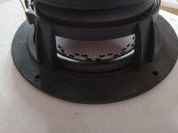
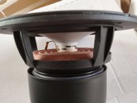
I bought this sub for cheap and I'd like to make better enclosure for it. But I can't figure out what model this is (tried reverse image search and one reddit post but no conclusion) and I have no way of measuring the t/s parameters now. So can someone identify this or tell me how can one measure the t/s parameters for cheap.
Or the not best option, could someone say what could be good ported box for this based on the sealed that it came with?

Thanks

IMG20241211161239.jpg
IMG20241211161531.jpg
IMG20241211161537.jpg

Small DIY 3D printed 3-way speakers for small alcove

I'm going to design and 3d print 3-way speakers to install on the sides of a TV.
Either active or passive crossovers. I have the tools to measure and make both.

The TV is 90degree wall mounted at the end of an alcove, which is about 2m wide and I'll sit on a bed, close to a wall, about 2m from the TV/speakers.
The height between the bed and ceiling is about 1.5m.

I currently have some spare SB19ST tweeters, a pair of Omnes SW 5.01 woofers and for midranges I have:
2x Tang Band W2-2243S
4x Peerless TC9FD00
4x Peerless TC6FC02
4x Peerless TC6FD00
to choose from.

I'm currently thinking of designing a waveguide for the sb19st and maybe for the mids.
Then I'm leaning towards an MTM with the TC6FC02.
And I've already designed and simulated the base for a T-line for the SW 5.01:
1733970118065.png
1733970310370.png


The reason I'm thinking of 3-way is because the SW5.01 is a pretty heavy midbass with a lot of xmax, so I don't know if it could cross over well with the tweeter.

Now my biggest concern is with the waveguide/horn for the tweeter and the placement of the midranges, to get the best sound in the small alcove.

I know it's not going to be perfect in any way, but I'm thinking I should try and make the speakers have a narrower directivity, to not get as many reflections.

I know MTM makes the vertical dispersion narrower, but I'd also want to make the horizontal dispersion narrower.
Should I just place 4x mids in a cross pattern?

Or should I make a unity horn with the mids?
Like the UICW: https://www.diyaudio.com/community/threads/unitized-image-control-waveguide.319698/
I'd use this one, but it's just a little large and I don't see anyone measuring both the vertical and horizontal dispersions, and I think it plays too wide.


Or should I just give up and live with the reflections?

I have a 32x32cm 3D printer so the design possibilities are pretty limitless.

For Sale Speaker set for the SEAS Classic MK2 kit from Troels

SOLD

Hi all
Selling some very good speakers for a project Troels developed -the SEAS Classic MKII
2 SEAS Prestige CA22RNY H1471-08 midrange - used, as good as new SOLD
2 SEAS Prestige MCA12RC H1304 woofers - new SOLD
2 SEAS Prestige 27TFFC H0881-06 tweeters - used, with brand new membrane voice coil units includ new front panels SOLD
Current retail price around 770 euros
Asking for 380 Euro plus shipping
Info: http://www.troelsgravesen.dk/SEAS-3-Way-Classic-mkII.htm

Attachments

  • SEAS Classic MKII.jpg
    SEAS Classic MKII.jpg
    459.3 KB · Views: 70
  • CA22RNY.jpg
    CA22RNY.jpg
    242.2 KB · Views: 58
  • MCA12RC.jpg
    MCA12RC.jpg
    147.3 KB · Views: 63
  • MCA12RC_2.jpg
    MCA12RC_2.jpg
    286.4 KB · Views: 57
  • Seas27TFFC.jpg
    Seas27TFFC.jpg
    274.7 KB · Views: 65

3eAudio DSP as Active Crossover in DIY Class D Amp

Greetings Friends. I have a DIT Class D amp I build according to this guide from IEEE Spectrum a few years back and it's been sitting on a shelf since I got into tubes. The amp has a 2x70w module from 3eAudio and their 2-in-4-out DSP based on ADAU1701.

IMG_20241211_091026564_HDR.jpg


Awww. my first amp.

Anywho, Now I build fancy tube amps and this poor guy is neglected. Alone. But smart and strong. I'd like to make him part of a hybrid Tube-Class D system. I have a little EL84 SE amp with glorious highs and poor bass. I'd like this amp to provide the bottom end.

I would like to program the DSP to be a 2-way Active Crossover, to send the lows to the Class D module and send the highs to a pair of output jacks for a 2nd amplifier. I have a pair of speakers with Bi-Amp capability, want to hear the magic.

I want to add a master volume control to the front end. I plan to add a 100k Log pot to the front panel and run the input directly to that, then to the DSP. Outs 1&2 will go to the onboard amp, Outs 3&4 will go to a pair of RCA jacks on the back panel.

There are 3 pots on the DSP. Crossover Frequency, Onboard Amp Volume, Bass Boost?

There are many projects out there for the Sigma Studio, is there one suitable for this? I suppose I could just watch the video where the guy builds a 2way from scratch...

thanks for taking a look!

w

Dahlquist DQ 10

I just grabbed a couple of Dahlquist DQ 10s for 200 Canadian is there a thread on this forum that can assist me with the subject of rebuilding them and potentially modifying the crossovers and possibly adding a passive rad to the back of the base cabinet I just registered on this site today so I’m not familiar with it my apologies for posting my question in the wrong section if I have done so

Attachments

  • 77238CE0-55D2-41DE-810C-4959B3484166.jpeg
    77238CE0-55D2-41DE-810C-4959B3484166.jpeg
    480 KB · Views: 521

new SCHALMEI feedback

I got a new SCHALMEI feedback:
The schalmeis can't keep up with the horn of a Klipsch, but that's not so bad.
These are satellites and they need support down below.
Previously only for cinema use, the 18 inch corner horn has now been integrated.
The speakers are now connected to my Cayin tube amplifier and are separated with a second-order crossover from 80 Hz. The corner horn is connected to the tube via a high-level input (Reckhorn A409). At first the Fostex 206 were installed but these were replaced by TANG BAND W8-1772 and now I am very satisfied with my satellite system.
I didn't know this dynamic before and the details were overwhelming at first, but now this system is the measure of all things for me.
I've recently had a pair of active Dynaudios (16800DM) with me and they can only do a little more in the treble, so kudos to your design.
1734033974930.png

Looking for opinions on which oscilloscope to go with

For about the last 10 years I’ve been using the same Rigol DS1102E. It’s alright, a decent two channel 100 MHz scope that gets the job done. About 4-5 years ago I got an old Tek 7603 with a couple 7A18 inserts and 7B53A trigger so that I would have an analog scope, but definitely use the digital for most everything.

I guess I’ve just become bored with the Rigol and was wanting to get something new, something with a bigger screen maybe. I’ve had my eye on a couple of the new Rigol 12 bit models, wanting to stick with 100 MHz or higher and wanting to go to four channels the options I was looking at were in the 700ish to 1000 range. Like the DHO924s. The DHO814 can be had for just under 500, has 100 MHz bandwidth and 4 channel, but not sure what is being given up at that price point.

Well, this past weekend was a local electronics get together/ swap meet. It happens twice a year here. I’m a vendor there so I get to go a day early to setup if I wish and also two hours early the day of to get first dibs on what I like before the public is let in. A good friend of mine also has a table there so he came early and knew I was looking to get a new scope. He has a buddy that also has a table there and only sells Tektronix equipment. He was a Tek engineer and service member (Tektronix was started in Oregon about an hour from where I live) and though retired is the go to for any Tek repair in the area. Anyways my friend saw a scope he was selling and I took a look at it. He offered it to me for a substantial discount on what he had it priced and if I was going to buy it I wanted to do it before the general public was let in. There were hundreds of people in line to come in. So I grabbed it.

It’s a Tek TDS 684A, 1 GHz, 5GS/s 4 channel scope. I paid 250 for it, it functions perfectly and is in fantastic shape, screen is nice and bright and the front panel is pretty much perfect.

Is it an upgrade from my old Rigol? absolutely. It feels to be much better quality. I saw the original price of this scope and was shocked. Cost as much as most cars. Will I ever use the 1 GHz bandwidth, probably not, but I don’t know.

So thoughts? I’m sure I could easily get my 250 back out of this scope. I see there are broken examples that sell for more. It’s approaching 25-30 years of age, somewhere in there. It has a smaller screen then the new Rigols, but I also got it for 1/3 the cost and in some ways it specs better. Should I keep the money I saved and put
It towards a new analyzer or power supply and keep this new (to me) Tektronix scope or sell the scope and spend the extra money needed for a new 12 bit Rigol?

Would love opinions
Thank you,
Dan

Your opinion on the parts I choose for my DIY Bluetooth speaker 2.1

Hello everyone,

My project is coming to maturity but before ordering everything I would like your opinion on my project.

Components :

HP + AMP :
  • Subwoofer 4 Ohm : Tang Band W5-1138SMF
  • 2x Full Range 4 Ohm (Re 3 Ohm): Dayton Audio RS100-4
  • Amplifier: AIYIMA Bluetooth amplifier TPA3116, 2.1 audio card, 2x50W for satellites, 1x100W for subwoofer. Link: https://a.aliexpress.com/_EQYXqNI
  • All connected by 2.5mm speaker cables

POWER SUPPLY :
  • Dayton Audio LBB-5v2 (5S with 5 26650 3.7V 5000mAh units), which will supply the amp with 21V in principle
  • charging via a USB C port that I'll plug into the back of the box

DIMENSIONS :
  • 18mm MDF wood
  • for the two satellites, each will be insulated in a sealed enclosure, dimensions based on parts express recommendations.
  • for the Woofer 6,6L with a Bass reflex of 2,5cm on approximately 14cm.

CROSSOVER :
No crossover, the subwoofer output on the amp cuts at 250Hz, and I'm using the full spectrum on the Full Range satellites, not particularly ideal but the sound should be pretty decent according to my simulations. There will still be a bit of dispersion at the top end of the spectrum, but a tweeter isn't in my budget!

I take all opinions and answer questions, so don't hesitate to ask!
One of my doubts concerns the impedance of the 4Ohm satellites (Re 3Ohm). Wouldn't I be better off with 8 Ohm?
And if you have any idea of the autonomy I can get with this battery pack, that would be great!

Thanks a lot!

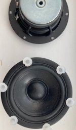
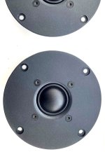
Crossover question?

I ONLY have my old DS-215-8 woofer , can't afford much more.
I am using a dome tweeter crossed over at 2K presently.

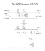
What I am curious about is the implementation of the (4th order LPF ??) and the 10R/22uf/2mH (notch filter).
The tweeter Xover is straight forward and works out in the calculators , but the 4th order is a mystery ??

MTG designs - https://www.mtg-designs.com/diy-speaker-plans/flex-8 -
has the PCB and schema to use this old woofer in what looks like a valid HQ design.
I am about to collect all the various iron core inductors and NPO caps for the woofer side of the Xover.

Is this strange implementation the "secret sauce' to tame the 1K-3K response of the LF driver ?
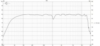
None of it works out in any online calculator but the result looks nice (below 2).
I might have better 15-20K with my properly padded dome tweeter , but I'm a little bit in awe of
this xover's complexity - would love to know how it works besides just being to identify the sections ??

PS - I'm running it now with just a 2K 2nd order on the woofer - sounds a bit bright in the vocal range.
REAL loud SPL 110+ , still a bit bright mids (but real clear) .....

I was running old (mission domes) at 1.2K - blew one of the tweeters !!

OS

Attachments

  • Flex-8 DS215-8 Schematic 5-10-23.jpg
    Flex-8 DS215-8 Schematic 5-10-23.jpg
    43.2 KB · Views: 141
  • Flex-8 DS215.jpg
    Flex-8 DS215.jpg
    78.9 KB · Views: 132
Projects by fanatics, for fanatics
Get answers and advice for everyone wanting to learn the art of audio.
Join the Community
507,551
Members
7,876,530
Messages

Filter

Forum Statistics

Threads
405,702
Messages
7,876,530
Members
507,551
Latest member
mbwiest