Hi everyone, I want to share and hopefully get some inputs/feedback on my first two-way design. Please feel free to give any notes/pointers on what I missed.
Background
I've been lurking this forum for years and has been fascinated by the design work of all the people here but never pulled the trigger on doing a build.
And now it's the start of a new year, I decided it's time to try and do a project.
I've set a few priorities for this project:
- 2-way design - I looked at this project as a learning experience and I think that I would miss out on the crossover design aspect if I were to do a full-range (which I believe is a very good choice for a first build for most people)
- Ported enclosure - similar to 1st point.
- Low cost - Since this is a first project, I don't want to spend big, but I also don't want it to be a very low quality build.
As for measurement, I know that a lot of people think that doing a design without measurement is only a waste of time (which I understand) but for this "kickstarter" project, I decided to hold off on purchasing measurement gears as the next step in my journey, just to have something to listen to at the end of the day.
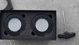
Driver Selection
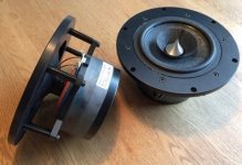
As for the drivers, the main considerations are availability and cost. Due to the fact that I live in the country where SB Acoustics are manufactured, it is pretty easy to get an SBA Driver.
I've been reading other people's designs with SBA drivers and I've read a couple of times that their published specs are close to real measurements, which is good for my non-measurement approach. Considering the low-cost target, I've went with their entry level 4 inch PFC series SB12PFCR25-4 and SB19ST-C000-4.
I use VITUIXCAD for every step in this design phase
1. Enclosure Design
I've inputted the parameters on the Enclosure Tool and come up with the tuning below, then I exported the SPL and Impedance
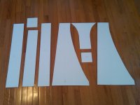
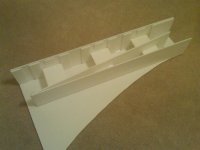
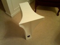
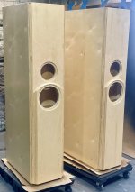
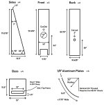
2. Baffle Dimensions
For aesthetic purposes, I try to get close to 1:1.62 for the dimensions, and considering the driver frames, I've came up with below design
3. Taking out IEC Baffle from Manufacturer Traced SPL
I would not go into details, but basically I followed the "design without measurement" guide on the stickied thread.
In summary:
- Trace Woofer Manufacturer data using "SPL Trace"
- Model an IEC Baffle diffraction response using "Diffraction" tool (Important note: SBA data is from 31.6 cm mic distance)
- Take out IEC Baffle from traced SPL using "calculator"
- Do the same for tweeter
As a result, we get the half-space response.
4. Simulate On-Baffle Responses
For the tweeters, I used the diffraction tool with the baffle dimensions above with a 1000mm mic distance on-axis, import the half-space response, and export the 4-pi response with simulated off-axis responses. (which is very not ideal from what I understand, since there will be a lot of uncertainties occuring in the off-axis, due to dome design, etc, CMIIW)
For the woofers, there are a few more steps I did:
- I modeled the baffle and driver location according to drawing above, with the same settings as the tweeter (1000mm, on woofer's axis)
- I exported out the raw diffraction/bafflestep response
- Import the half-space response of the woofer
- Export the full-space simulated response.
So we get 2 exported response (raw diffraction and simulated full-space with traced SPL),
Using the merger tool, I imported the exported SPL response from enclosure tool and set the raw diffraction response from Diffraction tool as the LF part.
The HF part is the exported full-space woofer response (with the traced SPL) from the diffraction tool.
Then exported the merged response
4. Main Software Page
On the main software page, I imported the following as my drivers:
Woofer
SPL - Exported from Merger Tool
Impedance - Exported from Enclosure Tool
Tweeter
SPL - Exported from Diffraction Tool (full-space on-baffle response)
Impedance - Traced Manufacturer Graph
I set 17mm as the z depth of the woofer (I've seen this number on another person's project while lurking, but can't seem to find the exact page. I believe it was acquired through the late Jeff Bagby's technique to find acoustic offset), and -105mm as the y offset.
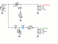
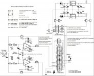
5. Crossover Design
The impedance peak of tweeter is at 1khz, and the woofer's response started to become messy around 4khz, so I decided to aim 2-2.5 khz as the crossover point.
After trying out and messing around, here is what I came up with.
6. CONCLUSION
Now what is remaining from me is to get any feedback from the forum, is there any steps I might have missed? Or if you have any input to the crossover design, what you would have changed, please let me know, I'm all ears for any improvements.
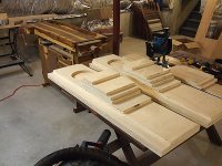
I'm planning to start the build in 2-3 weeks time so I still have time to make corrections and any changes.
And yes, after building the speaker, it is the plan to buy a measurement mic (I'm thinking UMIK-1) to conduct a proper measurement and validation of the design, and maybe design a new crossover using measured data.
Thank you, and looking forward to your feedbacks on this.


