Hi all!
I'm new to speaker design as I've only ever built kits in the past.
Like many before me, the TechIngredients Voigt pipe youtube video piqued my interest in Voigts.
Unfortunately, no frequency response graphs were published for it and so I decided to try and model it to see what it might be like.
I am new to hornresp and would like some guidance on whether I have set it up correctly. Based on the thread "Voigt Pipe Design", I think I should use direct radiator, transmission line, offset port, 3 segment, parabolic in input wizard.
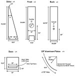
Attached is my exported Hornresp record. I have also attached the driver spec sheet, and the speaker diagram from TechIngredients.
There's a missing dimension regarding the height of the port. And rather than using 9.75" for the port width, I decided to use 10.625". I assumed the height of the port to be half the width of the port, hence in my sim the port is 27cm x 13.5cm.
I tried to draw the internal cavity within the cabinet walls in order to calculate the areas at the different sections. S1 = 1.9cm x 27cm, S2 = 21.4cm x 27cm and S4 = 37.5cm x 27cm.

I've no idea how to set L34 hence don't know what the right S3 would be. In the attached record, L34 is equal to half the port height. But doing so makes the schematic diagram look like the port extends beyond the "horn"?

In any case, what my input is like right now is:

Any guidance on how I can improve my inputs would be much appreciated!
I'm new to speaker design as I've only ever built kits in the past.
Like many before me, the TechIngredients Voigt pipe youtube video piqued my interest in Voigts.
Unfortunately, no frequency response graphs were published for it and so I decided to try and model it to see what it might be like.
I am new to hornresp and would like some guidance on whether I have set it up correctly. Based on the thread "Voigt Pipe Design", I think I should use direct radiator, transmission line, offset port, 3 segment, parabolic in input wizard.
Attached is my exported Hornresp record. I have also attached the driver spec sheet, and the speaker diagram from TechIngredients.
There's a missing dimension regarding the height of the port. And rather than using 9.75" for the port width, I decided to use 10.625". I assumed the height of the port to be half the width of the port, hence in my sim the port is 27cm x 13.5cm.
I tried to draw the internal cavity within the cabinet walls in order to calculate the areas at the different sections. S1 = 1.9cm x 27cm, S2 = 21.4cm x 27cm and S4 = 37.5cm x 27cm.
I've no idea how to set L34 hence don't know what the right S3 would be. In the attached record, L34 is equal to half the port height. But doing so makes the schematic diagram look like the port extends beyond the "horn"?
In any case, what my input is like right now is:
Any guidance on how I can improve my inputs would be much appreciated!
Attachments
Thank you Leif for the suggestion.
Can I please clarify. Do you mean that my model does not accurately represent the TechIngredients voigt pipe? And to improve the accuracy of my model I should not select offset port?
Or do you mean to improve on the techingredient’s design, instead of their front facing opening, I could employ a down facing opening?
I think Leif suggested an open TL being closer to the voigt pipe principle.
The siulation result will probably be very similar.
The siulation result will probably be very similar.
Ah thank you @stv for the clarification. I will try specifying an open TL in input wizard.
I had originally specified a TL with offset port as that's what David McBean seemed to have done in "Voigt Pipe Design" 😀
I had originally specified a TL with offset port as that's what David McBean seemed to have done in "Voigt Pipe Design" 😀

Thank you all for the guidance! After reading up more, I've decided not to proceed with the TechIngredients design. It seems like most on this forum who know a lot about Voigt pipes do not agree with quite a number of the design decisions the TechIngredients guy made.
It would appear a mass loaded Voigt pipe is the generally accepted ideal DIY Voigt pipe design. I believe the DDVP-20 qualifies as a ML-VP and I am going to try modelling that in Hornresp with a SB20FRPC30-8.
Given I intend to place the pipes quite close to the front wall, are the below inputs correct?
I noticed that the frequency response given by the loudspeaker wizard and the calculated acoustical power differ slightly. In the acoustical power one, there are spikes at around 102, 200 and 300 Hz which are not present in the wizard.
Which graph is closer to reality?
Thank you in advance for any guidance anyone may have for me.


Which graph is closer to reality?
Thank you in advance for any guidance anyone may have for me.
Attachments
Wizard graph includes filling, calculation does not.Which graph is closer to reality?
In this (and most) case the wizard graph is closer to reality.
- Home
- Loudspeakers
- Full Range
- Help Needed: Modelling the TechIngredients Voigt Pipe in HornResp