active boxes from 50y old SUPRAPHON RK-15

Did buy this old 2-way boxes and now tuning them. On the picture you can see a symetric amplifier i have constructed. I play to put this into the box so that they are active. They play better now although they play mostly mids and almost no bass. Thinking about replacing the mid/bass cone.

Also have to think about a new crossover. Currently only one 4uF foil cap is used on the trebles. Not sure if 4uF is what i want. What do you think Galu?

Attachments

  • supraphon_RK-15.JPG
    supraphon_RK-15.JPG
    47.4 KB · Views: 208

AK4490EQ DAC projects from DIYINHK

SOLD - 2 DIYINHK DAC kits - pcb with DAC chip and all SMT components mounted - Through hole components included but not mounted. Each pcb is a 32 bit 2 channel DAC with a choice of 5 filters. These DACs accepts up to 768 kHz i2s input or up to 11.2 MHz DSD input. They would make a nice compact and inexpensive project.

I bought them a couple years ago with the idea of making a pair of 2 way speakers with a digital crossover. Since that time, that project has slid down the list and I have become enamored of NOS multibit DACs, so I will never use these.

The DACs are free. You pay the shipping cost to Paypal. US and Canada only. Beyond that, the shipping cost gets out of line with the value. Send me a PM if you want them.

lehmanhill

SOLD - Thanks for looking

Extremely low QTC but Nearfield meaurement pretty flat

My new subwoofer build has been designed for an extremely low QTC and so far I like it. TO be honest, I wish I can get even more tighter and controlled but this isn't bad.

Anyway, for a .45 QTC you could imagine the roll off is really steep and no where near flat but when measuring nearfield I get a pretty flat frequency response. Of course when measuring from listening position I get all weird anomalies.

I measured from about 5cm away from the centre of the cone. I chose the sub(have dual subs) which had no side walls.

Have I done something wrong or can room gain really bring up the lower frequencies? This is what I planned but it seems to good to be true...

Or any other theories to this?

Arcam alpha one cd player

Morning
First time poster, my alpha arcam one cd has been in the loft for at least 5 years, today I powered it up and found it showed disc on the front panel
Took the lid etc off and I saw the disc was not being lifted, I did it manually and it worked
Any idea what I need to replace?
I have played a whole cd to make sure it reaches all parts and used next and previous

Ta Ray

Grounding scheme el84 amp

So, I need some help here. 5 years ago I built an amp modifying a cheap chinese kit. It´s a push pull pseudo triode with e88cc (9622) in the pre and driving stage. Basically its a triode connected "Bevois valley" without the voltage regulator. Its been serving me well for the last five years, and still does. However, I wanted to do the same thing over again, but looking better and with better quality trannies. So that I did a couple of years ago and got as far as populating the PCBs and getting it all in and on a chassi, trannies and all. All that was needed was the connecting. And there it has been lying on my work table giving me a bad conscience. But in these times we all look for something to do, and I got on with the project. Now it´s been 5 years, and other interests has gotten hold of me so I don´t remember everything I did ( and I was probably just following some instructions ) Anyway, I opened up the old amp, and this is where I run into problems. The power supply is on it´s own PCB and there is one ground in and one ground out. The ground from the three prong net cable goes to a ground on the power tranny´s primary. The 0s from the filaments and the secondary is connected to gnd in on the power supply PCB and the gnd out is connected to the amp PCB main ground point which is also then connected to the chassi. If this is the best way to do it or not I could´nt say, but it works. ( and has been working well ) Now my problem; the mains tranny on my new amp has no ground on the primary side. It´s a TRA400 from askjanfirst. There is just a N and 230v. I guess the problem isn´t really a problem if you know what to do, but I don´t trust myself with any guesswork. What should I do? Would really appreciate some help with this. Thank you in advance.

IEC 60320 C7/C8 Plug/Jack (Cable Connector) with Solder Terminal

In most cases there are to find this as a complete part - go to
Security Check
for an example.
A plug with solder terminals is here:
https://www.amazon.ca/kenable-Figure-Plug-Solder-Terminal/dp/B008IVMQ1O
but I am not able fo find a jack in a version with solder terminals.
Who can give me an advice or know the manufacturer of the mentioned plug ?
Thank you very much.

T/S parameters by engineering analysis

So, I'd like to learn more about determining T/S parameters for a candidate driver design prior to actually building a prototype. Can anyone point me to reference materials?

I am trying to assess some novel driver concepts. I have access to and decades of expertise using heavy-duty engineering software (including advanced structural and electromagnetic FEA). What I lack is experience in driver testing, which is obviously the final arbiter of quality, but if I can iterate a design numerically, it might help save time and money.

Any papers or links would be appreciated. Thanks in advance . . .

Audioengine A5+ transformer replacement

Hello,

I'm looking for a replacement for the toroidal transformer in my Audioengine A5+ active speakers.

I've had no luck reaching Audioengine Support, nor my local distributor. Basically I'd need to either find a transformer replacement, either use the speakers completely passive, hooked to a 4 ohm stereo amplifier.

Based on what I can understand from the photo I've taken of the transformer, its specs are as follows:

230v input
17v-0-17v
0-10v
15v-0-15v

What I'm looking for is help with pointing me towards a place where I could order online a similar transformer which will meet the voltages needed.

link to a photo of the transformer

Traynor Training Beta 800

Hi Folks;
The Latest project is a Traynor Beta 800, built just south of me, in Toronto. I almost thought I got the deal of the century; I replaced the line cord plug, and the amp seems to work perfectly!.....no DC on the outputs and a clean sine wave with my 'sacrificial' speaker.
The dummy load would prove otherwise. Chan A develops 42.7 V RMS. Chan B gets to 19 Volts, then colapses to spikes and oscillations. When the amp is powered down for 30 seconds, it seems to 'heal' itself, until the output again reaches about 19 V.

There is a schematic on the inside cover but it is in rough shape. I found a scan version of this schematic, on-line but just wondering if anyone has a service manual?

I've been warned about this amp, by knowledgeable folks here at diyaudio, but I hate to give up without a fight!

Attachments

  • DSCN0573.jpg
    DSCN0573.jpg
    986.1 KB · Views: 487

new guy here

retired, mid 60's central kansas,

background in mechanics and electronics


finally at a point in my life where i want to hear "my" music before i can't hear it anymore.


i also have an affinity for old stuff, particularly mid 60's japanese speakers, or rather the reuse of old drivers.


what really interests me is using these old drivers and building new and interesting cabinets for them, to get something enjoyable and useful as a result.


is there a particular forum or subsection i can be directed to, so that i don't end up upsetting those that think this is some sort of horrendous abomination.


😉


thanks
bob g

Converting powered speakers (M-Audio BX8 D2) to passive

Hello, this is my first post and I’d like to thank in advance to all who might comment or help.

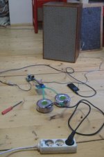
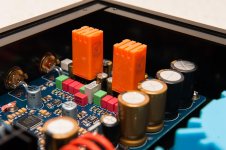
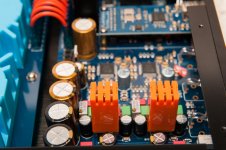
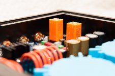
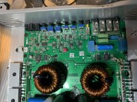
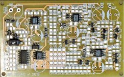
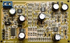
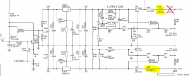
I have pair of M-Audio BX8 D2 powered speakers and one speaker’s tweeter line is busted. Tweeter is OK, but either dedicated amp on that line or crossover is busted. It is all on the circuit board and I am not in position to fix it. Authorized service is asking $75 in advance just for diagnostic so cost of repair can easily exceed $100 and I can buy a working, used speaker from Guitar Center for $135.

However, I’ve been wondering if I can go the other way… gutting all the electronics, adding passive crossover and binds and use those speakers with and amp like Onkyo A9010?

One option is obviously to make my own crossovers and the second one is to buy pre-made. How about Dayton Audio XO2W-2K 2-Way Speaker Crossover 2,000 Hz (Dayton Audio XO2W-2K 2-Way Speaker Crossover 2,000 Hz) or (https://www.amazon.com/Aoshike-Frequency-Divider-Speaker-Crossover/dp/B01NAKQS8V)?

Finally, is this a silly idea to begin with?

Below is a table with technical specs for your info.

Technical Specifications
Type - 2-way near-field studio reference monitors
LF Driver - 8-inch (203 mm) Kevlar curved cone with high temperature voice coil and damped rubber surround, magnetically shielded
HF Driver - 1-inch (25 mm) magnetically shielded natural silk dome
Frequency Response - 38 Hz – 22 KHz
Crossover Frequency - 2.2 KHz
LF Amplifier Power - 70 W
HF Amplifier Power - 60 W
Signal-to-Noise Ratio - > 100 dB typical A-weighted
Input Connectors - 1 x XLR balanced input connector and 1 x TRS balanced/unbalanced input connector
Polarity - Positive signal at + input produce outward LF cone displacement
Input Impedance - 20 KΩ balanced, 10 KΩ unbalanced
Input Sensitivity - 85 mV pink noise input produces 90 dBA output SPL at 1 meter with volume control at maximum
Protection - RF interference, output current limiting, over temperature, turn-on/off transient, subsonic filter, external mains fuse. [/TABLE]

Thank you!

Expolinear planar

Does anyone have experience with these? I want to get a pair of the MD-2000s for a project I am working on however I never heard these drivers before and they are expensive so I am hesitant to pull the trigger and potentially be disappointed. I am looking for a high end large planar to be paired a line array of RAAL 140-15s handling the highs and possibly an aluminum cone to handle the lows. Any feedback or recommendations for a large planar is greatly appreciated.

If I order the MD-2000s they are a dipole driver, would I be better off ordering a number of the dipole 140-15s as well? The goal is to make the ribbon array the same length as the planar. If the dipole isn’t the best fit for this application, would perhaps a few of Raal's Lazy ribbons be a better choice? I have a good amount of experience with the 140-15s but no experience with the Lazy ribbon. Looking for any feedback prior to ordering the parts for this project since it will be an expensive project and I rather not waste cash on components only to swap them out due to disappointment.

Rolls Crossover Question SX 21

The Rolls SX 21 (24db) is a bare bones crossover with a few basic features. I have read reviews that said the polarity is backwards, which is not the case but what are the options to correct phase?

I had some success with this project where the phase was 90 degrees [maybe 180 degrees] off; in any case there were no signs of a dip by reversing driver connections. I thought there may be a simple answer and added a 12uf cap at the tweeter, which was a huge improvement, although the tweeter connection needed to be reversed for the straighter response.

Are there other options?
Is a reverse connection a issue, or it just about the final response?

Many thanks!

Phase Q.png

Burson Audio V6 Classic experience

Hey everyone,

Had an opportunity to get my hands on a couple of Burson Audio Supreme Sound Opamp V6 classic which I installed on my DIY AK4495 dual mono configuration DAC. Been listening to it for a few days now and wanted to share here my findings with about 50hrs of playing time so far.

Packaging – The op-amps arrived via registered mail in bubble wrap, housed in clear plastic casing with each unit separated and held in place by sturdy closed cell foam. I don’t see how it can be damaged in shipping if handled correctly.

Installation - If you've never tried changing op-amps before, don't fret because it's quite easy. There’s a half-moon marking or notch on the Burson Audio op-amps to match the IC socket or slot in your device’s PCB. You can visit Burson Audio’s website for the detailed installation guide with illustrations. It took me about 10 minutes in total from removing the top cover of my DAC’s enclosure to closing it back in place.
Also, something to consider before purchasing is the size of these op-amps, measuring 12.4mm X 14.5mm X 29mm (0.48 in x 0.57 in x 1.14 in) which according to Burson Audio is the smallest discrete op-amps in the world. I was worried about the height (1.14in) as my DAC is housed in quite small form factor enclosure. With a little over a millimetre in height clearance, I was able to put back the top cover without issues. Another thing to check is if there are other parts closely installed to the IC socket, as you can see in the pictures, the plastic housing is touching the 2 capacitors on each side of the opamps but nothing to worry about.

Sound – I have a few IC op-amps to compare these with, there are distinct differences to my system’s sound when changing from one to another.
The Burson Audio V6 classic, was described as “engaging” on their website while the more expensive Vivid model was said to have “incredible dynamic range” and “three dimensional soundstage”. Though the latter would be something most look for in the sound of their system I wanted mine to be more engaging. The first time I installed the Burson Audio V6 Classic I spent an entire afternoon listening, then the next day, a Saturday I spent the afternoon switching from OPA627, to OPA134 to the Burson V6. Next day I spent the morning switching from NE5534, to LME49710 then to the Burson V6. The Burson never left the DAC since then.

The Burson Audio V6 Classic is as described, they are more engaging in a way that the vocals and mids are focused with just the right amount of details elsewhere and doesn’t add sibilance to the highs. I often listen to Melody Gardot’s Live in Europe album because I love the way she interacts with the audience and try to keep them engaged, in the track 10 “Baby I’m a fool (Live in London)” the banter between Melody and one guy in the audience and then she tries to imitate the British accent was very clear and made me laughed. Another favourite artist of mine is Ray Lamontagne, Trouble is one of the most played albums in my system, the recording is not what an audiophile would consider great but the music is fantastic. Ray’s raspy voice and the emotion he puts through every verse is extraordinary, and it seemed to me the experience was more enhanced with the Burson Audio V6 Classic.

My Conclusion – one question we all ask is if an audio item is worth the money and effort, I can say these Burson Audio V6 op-amps are. I prefer the sound of my system with it installed over the IC op-amps I’ve compared it with. I spent most part of an entire week comparing, swapping and listening to avoid the placebo or new gear excitement effect, still I like it in my system. And of course, result will vary from system to sytem so this still comes with the usual caveat; YMMV.

Attachments

  • BAV6_ckassic_1.jpg
    BAV6_ckassic_1.jpg
    865.2 KB · Views: 389
  • BAV6_ckassic_2.jpg
    BAV6_ckassic_2.jpg
    768 KB · Views: 322
  • BAV6_ckassic_3.jpg
    BAV6_ckassic_3.jpg
    162.5 KB · Views: 325
  • BAV6_ckassic_4.jpg
    BAV6_ckassic_4.jpg
    202.3 KB · Views: 334
  • BAV6_ckassic_5.jpg
    BAV6_ckassic_5.jpg
    200.3 KB · Views: 334
  • BAV6_ckassic_6.jpg
    BAV6_ckassic_6.jpg
    213.6 KB · Views: 119
  • BAV6_ckassic_8.jpg
    BAV6_ckassic_8.jpg
    891.3 KB · Views: 112

W20RC38 / Morel CAT 298 [or MDT 28]

A new build with left over drivers and parts. I'm sure many folks would enjoy low cost build that sound great and play loud!

Started off as a rebuild of old boxes that was a DIY build from 20years ago, but the old boxes will full of nails/staples. Pitched that pair and started over.
The only salvaged parts are the PCV ports.
However, during the first attempt I did find a SF/Morel xo in Madisound's LEAP library.
The plan called out CAT-298 but I've been storing Morel MDT 28/30 since early 80s in hopes of project. Note that all the tweeter VCs do not have any ferrofluid left, evaporated I guess.

Ok then, built new boxes .75cf [net] fingers crossed I tried the old morels and was very happy with the measurements/results (3rd photo).
[the tweeter resistor was increased to 5.6ohm]

The woofers were on the shelf also, W20RC38/8, checked WinISD and used 2" PCV with router round-over bits. Fs tuning is in low 50s.
I also found that the 8" SF needs a 1lb of damping material and used the Blue Denim building insulation.

So far a no cost project, although I did order 900 units ferrofluid: guessing 4 5 drops should be enough for each tweeter.

* Morel - Bumble Bee speakers, they really shouldn't work lol I'll never forget reading that in a google search that took me back to DIY.

Attachments

  • SF Project.jpg
    SF Project.jpg
    81.1 KB · Views: 319
  • SFMorel.png
    SFMorel.png
    155.4 KB · Views: 328
  • W20RC38 8  R.png
    W20RC38 8 R.png
    100.3 KB · Views: 319
  • Boxes.jpg
    Boxes.jpg
    96.2 KB · Views: 311

Adding a clear coating layer for paper cone

I've a pair of Seas ER18 RNX - reed paper cone version.
In my tropical country, humidity is real problem with paper cone.
Some friends have the same problem with Scan speak woofer classic when the humidity destroy the join welding of voice coil wire with the terminal lead wire ( through the paper cone!).
If I spray a clear coating of atm painting on the cone, is this affect (much) to specs of woofer enough to change the sound?

hum in harmon kardon pm665

When I engage the Bass Contour or loudness contour switch the unit hums in both channels, even with the volume all the way down.

When the Loudness is off unit does not hum, even at full volume. This amp has special Harmon Kardon Phase Correction Loudness.

Is there an area on this high power integrated amp I need to look. Perhaps the part of the power supply that the loudness circuit gets its juice from?

Peavey CS800 not powering up

Bought a Peavey CS800 power amplifier and upon pickup this guy that looked like he was ready to kneel over and die had set it in a pile of melted snow in his driveway. It made a mess of my car but when I got it home I took it apart and let it dry for two day. Cleaned it up.

tested the power switch and it works fine. Tested the power transformer and it reads a 0.3 - 0.5 ohms upon leaving the secondary side and entering the fuses on the power board on both leads. Does this mean the power transformer is good as well as the switch?

Line level / interconnect cable – maximum length and what cable?

A family member asked me if they can play their TV audio over the hifi. Sure - that’s easy with an interconnect cable from the TV audio out headphone jack to the line-in RCA on the Marantz amp, right? Only caveat – this cable needs to be 15 meters (about 50 feet) long if routed to satisfy WAF. Is this feasible at all and what kind of cable do I use?

How important is the thickness of cabinet wall?

Hi, I’m building a pair of floor-standing speakers. The height is about 120 cm. Width 29 cm. And depth 36 cm. At first, I planned to use the 20 mm. MDF as the cabinet walls and 1-inch thick MDF for bracings inside the cabinet, as seen in some commercial speakers. I went to my local carpenter shop, he usually build car speaker enclosures, and had him build my speaker cabinets. Unfortunately, he used wrong thickness on my pair. He used 12 mm. MDF totally, the bracing construction and dimension are correct every point though. He offered me discount for these cabinets due to his mistake. I’m now hesitate whether I should accept his offer or not. Could anyone please tell me what is the result of using thin cabinet wall? What way will the sound go and affect? I’d like to know if the sound is distorted, how? Bass boom, Midrange echo, etc. Please explain me. Thank you in advance.

ATTENTION

Dear All Aspenites,
It may have fallen under your radar but the Aussie Dollar has now firmly entrenched itself at under 70 cents US. This is a great time for all to update those older Aksa's, Naksa's and Lifeforce's to new Saksa's and Maya's. This is a great opportunity! Now is the time to move up to better music enjoyment!!!

Need guidance on (focused) music player for Linux.

I want a Linux based music player that does this, after I execute the playback.

1. Decode and store the full music to RAM.

2. Communicate sampling rate, bit depth etc to usb dac via usb audio class 2 protocol, and if possible do a short sync.

2. Remove all handles (no scrubbing, no seeking etc) except play, stop and pause with keyboard interrupts. Probably even remove mouse/trackpad polling, and stick only to keyboard.

3. Play the song.

4. Have option to change volume alone (communicating volume to dac directly through usb audio class, not software volume control) when needed, again through keyboard interrupts.

Make sure that it is very focused and instruction sequences are fully about music playback and music playback only, by starting and incrementing memory (instead of checking for user input on location everytime, stealing instruction cycles).

I recently tried hysolid on windows and I was blown away. It has its control done via a smartphone app, using wifi but the concept is the same with respect to playback. The sound is a serious improvement over other players I've tried (difference is higher than moving between multiple class of headphones). I'd prefer if it ran on 64 bit engine, which imo is the only improvement I see missing in hysolid (other than it being windows exclusive and having to put up with other daemons in windows).

I tried ap-linux yesterday, and wasn't satisfied. The installation procedure, for a Linux noob like me was super hard and a friend guided me through it for hours together. After installing i found that it had 3 players - deadbeef, audacious and cantata, with a realtime kernel on the system. I don't think it felt in any way better than winyl on windows and a far cry from hysolid.

Since it was too buggy to try around, I've removed and I'm installing gentooplayer by the recommendation of a friend. Would like guidance on the music player setup as per requirements above. I saw that it allows to have ramdisk to store the music but I am unsure if the playback engine works the way I described above.

I also tried to experiment with daphile but again I encountered issues with network connectivity etc (surface book doesn't have ethernet and it's wifi chip seems complicated, and bad imo).

I am open to experimenting with other distros - my laptop is surface book. I need to dual boot, and can't compromise windows. I am less interested in remote control, though I am okay with it if there's no other way. I want to use windows for other purposes, and Linux when I want to jam out with music.

Almarro 318B: Help with Biasing

I am having trouble getting my Almarro 318B to bias down to the correct 200mv range. I have put in new power tubes on a couple of occasions and it seems that within 2-3 weeks, the tubes start to run hot. I am already biasing at the minimum. Is the a symptom of a problem that needs fixing?

The problem seems to have gotten worse over the years. I have tried all the NOS Sovteks out there from the late 60s to early 80s.

I am going to bring the amp into a local amp repair technician but want to give him a start on the problem.

Thanks.
Dave

Need some help- adding a 1" tweeter?

I have a bluetooth player I picked up off Ebay. Its basically a receiver/USB player with a sealed sound box, two speakers, one on each end. Its been made to look into a faux gramophone, which looks pretty cool. It also has a round resonance "flapper" on the bottom, which adds bass. That is not really a speaker, it just vibrates.

The whole sound scheme is pretty good. However, I was disappointed to find that the horn on top, is basically dead weight and no sound comes out of it. Its just screwed into the back of the box, with no opening through to the box at all.

I know enough about acoustics to realize that a sound box needs to be sealed, etc. For example, when you unscrew the top lid and take it off, practically all the bass is lost.

So here was my idea.
I'd like to buy one of these 1" tweeters, and stick it in the mouth of the horn. Then run a wire, through the sound box, to the reciever:

1-INCH 260W MAX POWER SILK DOME NEODYMIUM TWEETERS - PAIR | eBay

The sound box would still be sealed, just a small hole for the wire down through the horn, which could be closed with silicone. That way the horn would actually work, and in theory, it would improve the overall sound.

Would doing this however, reduce power to the existing side speakers, make them quieter? Is this idea doable, or just a waste of time. Thought I'd get opinions...... thanks

Attachments

  • player.png
    player.png
    469.4 KB · Views: 193

Help me set up my speaker building room

Hello. I just moved, and now have a small workshop, I can use for my speaker building. Because it is small, I need to come up with some really neat ideas for a multi use work table / table saw, etc table. I see the table top probably being in the 4 ft x 6 ft range. This table will need to be on lockable rollers, where I can maneuver around it easily. I'm thinking I may run an electrical line above head, with a power strip up there, and make all of the power cords come down from above. I can see the need to be smart about utilizing the under side to build a low shelf the same size as the table's top. This allows mucho storage for clamps and power tools.

Any and all suggestions are welcome ! And thank you.

Active subwoofer Q

Looking at the variety of commercially marketed active subwoofers from all the manufacturers, it is quite apparent that most of them shrink the box down to the smallest practical size. A typical unit might use a 12 inch driver in a 40 liter sealed box. Through the use of equalization, the resulting sub has (or is claimed to have) a response down to 20 Hz.

Are there any practical guidelines on how much equalization can be tolerated before sound quality degrades? Are there other considerations or trade-offs to shrinking a subwoofer box down to well-below optimum size?

As an example, the SB Acoustics SB34NRX75-6 12" woofer would seem to work well in a 100 liter sealed box (Fs=19 Hz, Qts=0.4, Vas=260, Xmax 0-peak= 11mm). If this box were shrunk down to 50 liters, the resulting system would need a boost of about 6 dB at 25 Hz and a cut of 1 dB at 70 Hz to match the optimal 100 liter box. What are the down sides to shrinking the box and doing the equalization (other than the need for DSP and plenty of power)?

Thank you for your thoughts

Stetsom 10.5k power supply won’t boot up

I have a Stetsom 10.5k amplifier that came into my shop with some shorted
output mosfets. I replaced the mosfets on both sides and the gate driver ICs
on both sides and the logic gate ICs on both sides. I also replaced the gate
resistors that were out of spec and few of the diodes around the output
mosfets were replaced due to shorting.

When I feed the amplifier 14.5 volts the amp gives me an undervolt error. I
replaced the diodes in the undervolt circuit and replaced Q27 with a BC817.
I also checked the resistors and capacitors in the circuit and they all
checked good.

I removed R127 and jumpered pin 8 to pin 14 and started the amp up and now I
get an overvolt error. I was wondering if anyone could offer suggestions as to what may be the issue.

The power supply never tries to boot up. The amp goes straight into
protection. No rail voltage is being produced.

The amp has a 14 pin PIC16 chip. These are the pin voltages before I installed the jumper.

1. 4.97
2. Crystal
3. Crystal
4. 4.11
5. .005
6. 4.70
7. .002
8. .005
9. .002
10. .003
11. 4.64
12. .010
13. 5.60
14. .003

I am including a photo of the area in question.

Thanks,
David

Attachments

  • image.jpg
    image.jpg
    1,019.4 KB · Views: 129

LXmini Kit (+more) Philly area?

I bought the LXmini kit a couple of years ago and I am not going to get around to building the speakers. So, I have the kit and some extras (like pvc pipe, the large rubber things at the top, and more). Some of these things I wouldn't ship.

My first attempt at moving this kit to someone who will give it the attention it deserves would be to find someone in the Philadelphia area who wants the kit and the extras. BTW, my zip code is 19075. You can see generally where I live.

If you are interested please PM me and we can discuss everything I am offering. And I should add that I do not have the wood pieces. I have the basic driver kit and some other things.

Small 12V transformer or power supply

Hi:

I am in the process of restoring a GAS Son of Ampzilla amplifier. The original non functioning VU meters and the rudimentary meter circuit is being replaced by newer meters and an independent IC based driver board.

For the driver board and VU meter lamps I need a 12V supply; the driver board can work with either DC or AC for which I need a separate transformer or power supply.

The challenge is that the space inside is very limited. Can anyone recommend a small size 12V power supply or transformer. I believe the current requirement should not be greater than 400mA. Alternately, could I tap 12V from the +/- 51V and +/- 45V rail voltages?

Thanks
Mayank

betsy wow and ribbon

I started work on the bookshelf speaker for a friend. Now this is something special, I can't stop listening to this speaker. Phenomenal coherency.
Anyway, I got G2 ribbons from nice diy fellow here, I got betsy wow from 'd to the g', and placed betsy wow in closed box (ikea bookshelf).
I removed the dust cap, installed brass phase plugs and coated the cone with the 'wet look' from parts express.
Measured the response, I can post it later, it was gently rising, minor breakups, rolls off at ~10kHz. I applied the bsc (0.5mH, 10 ohm) to flatten the response. Measured again, added ribbon, settled on 2uF cap. Nothing more. Flat fr response, flat phase (i tested in and out of phase). I listened with and without sub, sub is optional, depends on personal preference.
Anyway, I build betsy and ribbon before (old thread somewhere), this approach works. This time result is even better.
You got to hear it to believe it.

Attachments

  • br2.jpg
    br2.jpg
    753.7 KB · Views: 1,227
  • br1.jpg
    br1.jpg
    483.9 KB · Views: 1,225

WAF : which enclosure for FE 206 ES-R ?

Gentlemen,


I posted a message a while back for a "simple to build" enclosure for the Fostex FE 206 ES-R.

From this post, I received a lot of good advice from Scottmoose for building a BIB -TQWT. He even did the calculations for me (thanks again BTW). So everything was ready to R&R.

So I was all ready to go, except that I discounted the WAF in my plans : my future ex-wife threw a serious tantrum when she look at my plans and discovered that these beautiful boxes would be over 2 meter tall...

Not planning to move out of the house in the near future and be forced to sleep in my car, what recommendations would you have for an enclosure taking care of the Wife Acceptance Factor.

1) Fostex recommended enclosure for the FE 206 ES-R ? as per the attached file.

2) A Nagaoka D58-ES ?

3) Others ??

Thanks,
Sierra

Attachments

Help with Identifying 12AX7s

Hi!

So a few months back I got an old Ahuja HRC-32T tube amp with 2 EL84s in class AB and the seller told me that it has 3 ECC83 (12AX7) in it.

Well, the labels have come off and 2 of them seem similar while the other one looks a bit different.

Can anyone help identify these tubes? If they are 12AX7 or not and the manufacturer.

The 2 similar ones have filament flash, their plates are shorter than the other one, and they have circular (not oval) holes on each sides of the plates while the other one has no holes. Also, the 2 similar tubes are a tiny bit (1-2mm) shorter than the other one, but that could just be a tolerance thing.

I have attached the pictures of the tubes down below.

Thanks everyone!
20200326_171059.jpg

20200326_170937.jpg

20200326_171200.jpg

20200326_171242.jpg

P.S. Sorry about the upside down pictures. They were fine on my phone, don't know what happened.

100 power amplifiers to lift your hat

I came by pure luck on a web site written by Kurt van Lilienthal Heitmann Thaaning Steffensen. A large collection of 100 amplifiers schematics and descriptions, starting from "The Audion by Lee DeForest, 1907", until "Luxman MQ-50, 6550 PP, Stereo, 1983". I'm not qualified enough to estimate the quality of the analysis but from what I read the author seems to knows his business.

Some gems in there :

  • EL6471 is a typical example of such amplifier. It is a class B power amplifier rated at 1000 Watts and it runs at about 3200 Volts. The weight of this monster is 155 kg.
  • Altec 260A, 813 PP 1956, now, we are talking…Look at this at this thing…1,2V RMS at the input terminals and you will have some 260 freaky ALTEC Watts to feed your speaker !
Enjoy while you are locked down 😉
  • Like
Reactions: Svytoslav

FS, Original style Magnequst (pinstriped) EXO-173 transformers

For sale, Original style Magnequst EXO-173 transformers, these are "pinstriped" unts (M6 and nickel)... and are housed in solid brass channel frames. They are a 4 terminal autoformer. They can be used in several different ways. They can be arranged as a 1:2 step up and as a 2:1 step down transformer. EXO-173 can not carry any DC Current.
I have two pairs for sale,
My price is $140.00 a pair plus shipping(Both pairs Sold)
EXO-173.jpeg

PHIDac SE build and questions

Hi All,

A while back a kind gentleman (Matt Garman) sent me one of Richards PHIDac kits. After much torture soldering ant sized SMD components I think that I'm ready to power it up and give it a try. At first I'm going to try feeding it I2S from an old ministreamer that I have. I do have one question about the output. It is single ended leaving the board, but in some pictures that were posted it looks like the output from the DAC board is put through some output transformers. See the first pic, The other two pic are of my build. Do I need output transformers. Appreciate any help.

Paul

Attachments

  • other build example.jpg
    other build example.jpg
    379.4 KB · Views: 458
  • Phi begin.jpg
    Phi begin.jpg
    334.2 KB · Views: 448
  • Phi populated.jpg
    Phi populated.jpg
    335.7 KB · Views: 450

Strange Frequency response?

Hi! This is my first post on this forum, if this question is in the wrong place I apologize. I've been working on a diy boombox using Dayton Audio RST28F tweeters, and I've noticed the frequency response at the top end looks kind of funny. I know these tweeters are supposed to reach all the way to 20khz, but my measurements show that the -3 db point is around 12 khz? Is this normal? The speaker really sounds fine, I can't hear anything lacking in the treble, but just the measurements show a sharp drop off after 11-12 khz. It could very well be that I'm measuring it wrong, I'm using a umik-1 mic with room eq wizard. I did check and confirm the test is going all the way up to 20 khz though. Here's the graph: EcstasyFrequencyResponseSixth.jpg

Oh and btw, these measurements were taken outside, so room acoustics shouldn't be an issue, even though I don't think it matters anyways at frequencies this high. I'm sorry if this is a stupid question, I'm still very new to a lot of this stuff.

6DJ8 supply voltage

Hello everyone. I am designing a compressor with the 6DJ8, but it's my first time dealing with tubes. Its datasheet shows maximum plate voltage rated at 130V, as shown below.

DmjB9Tt.png


I am designing the amplification stages by biasing the tube from the plate characteristics curves below. At first I was considering the maximum plate voltage of 130V for the bias, as shown in the red curve. The operating point of the tube would be 86V in that case.

A fellow person told me that the maximum plate voltage could be higher than the 130V (as it shows in the "cut-off condition"), and that this value is only there to avoid too much power dissipation, considering the maximum current allowed.

I wanted to know if it is possible to bias the tube say, on the green line, and supply it with ~200V, considering the operating point of ~117V, as shown below. What are the implications of it in a compressor? Is there any danger in going above the 130V?

p4WK5ha.png


Every tiny bit of information and knowledge is really important to me. Thanks in advance, people!

Needed: SONY TA-1120F Schematic or service manual

How is it possible that a model can be made for several years by a huge corporation and nobody seems to have a service manual or schematic for the Sony TA-1120F - this is the third version of the TA1120 that uses FETs in the preamp and has a completely different power amp section.

Even if it sold only in Japan, you would like to believe that at least one person who worked at Sony or in a service outlet might have one usable copy and be a member of an audio related on-line social group.

I have received a unit that has a functional power amp but has a problem in the Line stage that causes one of the main filter cap voltages to raise up about 30vdc from about 50v to about 80v and causes the other filter cap to decrease by about 30v from about 50v to 20v. I have found that when the B+ is disconnected from the line stage (but not the phono stage or tone control boards) that the voltages remain correct and stable. When I apply the B+ to the line stage board, it causes the 30v shifts.

It would be great to find a schematic...

Does anyone have pictures of the back sides of the three preamp boards that they can share that shows where the wiring is attached to the traces?

I have not pulled all of the transistors from the line board (the middle of the three boards) but I have done some in circuit ohm and diode tests and nothing seems wrong. I received this unit following someone elses attempted repair and I am wondering if they have placed a wire on the wrong trace. I really hate having to reverse engineer this unit, but it sure looks like that is where this is headed.

Can anyone help? No need to reply if you have no idea or no experience with this model.

Thank you!

ALEPH 5 Oscilating 600KHz

Hello, I have build my first Aleph 5. Schematic bellow. I have matched IRF9610. Rail voltage +-34V


I have start with just one pair of IRF244 before adding others. When I connect dummy load 8Ohm, everything seems OK. 13v peak to peak before clipping- that is power output I would expect.

When clipping started around 14.5V, it clipping only postive side of sinewave, negative is ok even in much higher output. Somehow assymetric clipping... If I have added more output mosfets, clipping was symetric. With just one pair, always such assymetric - however same behaviour on both channels. Is it something I should deal with?

If I connect 6Ohm speaker instead of dummy load, there is quite big oscillation - 600Khz. Suprisingly, if I lower rail voltage to +-10V, everything going nice. No Oscilation and THD even lower then with +-34V, maximum output voltage cca 14V pk-pk. However, when rail voltage go over +-15, imediatelly there is big 600Khz oscilation.

As it is my first Mosfet amplifier, Im little bit lost how to prevent the oscilation. Im thinking to try increase gate serial resistor from 221 to 1K. Thinking to add some capacitors between Gate and source...however not really sure where to focus first.

Really appreciate any help from more experienced guys here, what should I try. Thank you in advance.

Attachments

  • aleph-5.gif
    aleph-5.gif
    13.6 KB · Views: 1,095

The classis Push pull vs Single ended question

Hello guys. I dont want to repeat this question once again, but is stands against me.
I have homebuilt fullrange open baffle speakers with 93dB eficiency and I have used these with various single ended triodes like 45, 4P1L which can make only small power, 2 watts maximum.
I want the good SET sound, but with better bass and power in general. You will think that good option is to build bigger Se, for example with 300B or simillar power tube. I dont have this option because I have only small power OPT (from rema radio, 5k, 35mA, but these sounded actually pretty good).
With single ended triode, even this small power I get BEAUTIFUL, really GREAT soundstage and things like vocals, timbre, image are great.
Biggest problem is bass. The amp has these great things but at the same time lacks bass energy.
But I have push pull output transformers which were intended for EL34s in pentode. These can have 3.5-4k on each side of the primary.
I can be fine with 4 watts of power.

I have two most important questions:
1. Can I use these output transformers for, for example EL84s in triode or simillar valves?
2. I know that with pushpull I will have better bass, but what about the other things? Timbre, detail, soundstage, imagination... Wouldnt be these worse than with SE amp? This connects to another question which is what good pushpull circuit to use.
Thank you for your time and suggestions.
Best regards, Michal

Dayton Titanic MKIII 15" Subwoofer

I recently acquired the above mentioned subwoofer in like new condition. I am trying to determine what the best build type would be for this sub. Home theater use with some but very little music use. I will for sure want it to be vented, but I'm not sure on what orientation. Down firing seems to have my attention right now. Any other configurations that I should consider? Any designs or plans anyone has that I could work with for this driver? Thanks!

Switching issues...

I built 12V6 PP monoblock amps with a differential front ends using a 12SN7. The amplifiers use no feedback. I like to have a mute switch on my power amps and, on these amps i also have both single-ended and balanced inputs. So installed a 3-position switch:

Position 1 - balanced input: source connected to the two 12SN7 grids
Position 2 - mute: 12SN7 grids connected to one another no sources attached
Position 3 - SE input: source + connected to 1 12SN7 grid, source earth connected to other 12SN7 grid plus second grid is connected to circuit ground

Initially the Mute position connected both 12SN7 grids to earth but that gave a large thump when used so I reverted to the above configuration.

All worked fine with single-ended inputs and balanced outputs from my Benchmark DAC1 directly into the power amplifiers. I could switch between SE Mute and Balanced with no problems.

Then I built a transformer coupled preamp (Lundahl LL1680 9:1 driven by a 6J5) the output winding of the LL1680 is floating for balanced output (according Lundahl spec sheet) and one end of the winding is grounded for single-ended output.

When using the preamp in balanced output there is a large thumo when switching between mute and balanced output. There is no thump when using single-ended output switching between mute and the S#E input.

I have tried creating an artificial center tap on the winding with two 1k resistors to earth for balanced, but still a large thump when switching.

What gives? As I say when using my DAC's balanced output this does not happen...?

Scan Speak, SB acoustics, Fostex drivers sale 30psc

Hello, I’m selling some drivers . PLEASE note they can be sold ONLY in EU countries where parcels do not cross airport security check) Roughly 30% Woofers and 10% tweeters shipped worldwide was returned as dangeruos materials and shipping costs was not returned. Wire bank transfer or Paypal (add 5%) are acepted.


1) 2psc Scan Speak D3806/820000,NEW never used ,only took out for measurements (box/packing have storage damage) 90eur/psc (MSRP 180EUR/psc)

2) 2psc Scan Speak D2905/990000 tweeters. They have new replacement domes from scan speak fitted, one edge of the flange are cut to make it closer to woofer. I can glue/weld and repaint it. 85eur/psc (MSRP 220EUR/psc) SOLD


3) 10+ psc Variuos Scan speak 18w8545/18w8545K /18w4545 (4ohm) Paper carbon clasic series woofers and MIDRANGES (built for Wilson Audio Watt Puppy 7/8 speakers) 70-90eur/psc (MSRP 140-400EUR/psc)

4) 2psc Scan Speak 12M/4631 COATED cone version (center dome was sligtly pushed) 115eur/each (MSRP 260EUR/psc)


5) 4psc Scan Speak 18W8530K00 COATED cone those were 4 ohms versions(built for Alpine F1 status speaker system) but coils replaces with 8 ohms- GENUE scan speak parts. Very light loctite glue is used for repairs 80eur/each (MSRP 200EUR/each)

6) 2psc Scan Speak R2904/700005 tweeters, have some sratches and marke on flange magnets 120eur/psc (MSRP 300eur/psc) SOLD

7) 2psc SB Acoustics SATORI MW19P-4 used for measurements and less 10 minutes playing test 100eur/psc (MSRP 190EUR/psc)
SOLD
8) 2psc SB Acoustics SATORI TW29DN-B nealy new with boxes ,used for measurements and less 10 minutes playing test 100EUR/psc (MSRP 150EUR/psc) VERY EFICIENT tweeters, perfect match with Fostex 8 inch SOLD

9) 2psc Fostex Fostex FF225WK 8" nearly new with boxes ,used for measurements and less 10 minutes playing test 130eur /psc (MSRP 170EUR/psc) please note – they are NOT fullrange drvers - unless you are 70+ years old and have accelerated presbycusis.

10) 2psc Fostex FF165WK with boxes ,used for measurements and less 10 minutes playing ,one of the drive was modified ( remooved dust cap, and glued back with ultralight glue- frequency respone is same as other driver,measurement swill be included if needed) 80eur/psc (MSRP 110EUR/psc)


11) 2psc [/B]Dayton Audio DS270-8 [/B] 10 inch woofers. [/B]nearly new, with boxes ,used for measurements and less 10 minutes playing [/B] 60eur/each (MSRP 85EUR/psc) SOLD

magnetic momentum

Its the 250VA toroidal transformer building up magnetic momentum. Are you using normal or time delay (slow blow) primary side fuse?

During my long research on transformer/inrush current, I once stumbled across this long info-sheet about exactly the magnetic momentum of transformators. It's in german, unfortunately, but as far as I understood (that's not that far), it is adressing exactly this issue.
If I got it right, it manages the electric/magnetic impulse of a transformer, but not the inrush current into the capacitors...

Maybe some knowledgeable mind can chime in for more details?

david

Attachments

Rubber Renew on Butyl Rubber Surrounds??

Has anyone here tried Rubber Renew on butyl rubber cone surrounds?? I was wondering if it really works or not. I noticed my Dynaudio woofer surrounds are beginning to oxidize and harden little bit and replacing all of them will be expensive as I have to get them from Dynaudio USA and Dynaudio USA has to get them from the Dynaudio factory and make their usual cut as well... That brings them to about 400 USD each! I can have foam surrounds installed but I don't really like the idea of foam surrounds because I don't think they will allow the drivers to maintain the original specs. Any thoughts??? The drivers are 24W75's.

Rubber Renue | MG Chemicals


Thanks!

Mark

NAD 2100 in protection, -45V rail too high

I'm starting to pull my hair out on this one... A little background first....

I re-purchased this amp cheap from a friend who blew it up. Most of the output transistors and their drivers on the right channel were toast.

As it sits now, there are absolutely no output transistors in it (center heat sink is completely empty) and there are no drivers in it either. I'm stumped as to why it still won't come out of protection mode. The one thing that is baffling is that I'm getting good voltages everywhere except the -45V rail (low-power side of the power envelope). I get -65.9 volts on 4-ohm switch position or -71.1 volts on 8-ohm switch position. The 10000uf/50v cap (C510) is in danger. That -71 volts travels everywhere and I don't know where it is coming from. I've checked just about every transistor, resistor, diode and cap in this thing and can't find the problem. AC voltages from the transformer to the fuses and the rectifiers are all good.

Anyone who has experience with this amp and could help me, it would be greatly appreciated.

Taramps 12k amp stays on protect mode

Hello i am new here, i have this car amp where it wont come out of protection mode, originally problem was battery terminals were reversed.
I have replaced all transistors on the power supply side and 1 side of output transistors and found burnt traces(same side). That side seems good now. Also the 2 driver ics for what I think is output transistors. When everything is together, I get the red light flashing twice and manual says that means voltage is under 9 volts. I am giving 12 v of course, but 4 rectifiers are getting about 8-9V and the other 4 (outer ones) have 0 volts on all legs. This is my first time repairing an amp so idk if it should be like that for the outer ones, but i heard that somewhere around there, there should be a high dc voltage like maybe 80 volts, created from the transformers, that is nowhere to be found, so i think the "gate driver(s)" is the issue and it is not pulsing the transistors on the psu side? Sorry i dont know much, just appears that no high voltage is coming out from the transormers or transistors. I found these 2 tiny ic chips and think they might be the ones responsible for pulsing but i am not sure. I will attach pictures, i cant find these ic parts online either way. The picture has the ic blurry so here is what they say: "8CA 524A". They are smaller than DS0 package size. Also when i removed rectifiers, amp stays on protect mode steady red light but i dont think thats useful. The ic's i already changed are the "s18244 " ones btw(i think this is for output fets). Any help would be appreciated

Attachments

  • 20200326_204835.jpg
    20200326_204835.jpg
    855.2 KB · Views: 293
  • 20200326_205434.jpg
    20200326_205434.jpg
    915.6 KB · Views: 714

NAD Amp Repair (Newbie)

I have the NAD Amp with the service manual attached. I'm hoping someone can help me diagnose a issue. The amp stopped working a while back. I finally got around to taking a look to see if I can find the issue.

Symptom:
Amp light would turn on, you'd hear two 'clicks' (relays) but nothing worked. No sound output no matter what input was selected.

Sorta cause:
Resistor R46 (In attached capture document) was open. Looks like it got too hot. I ordered a replacement 51O 1Watt resistor and put it in today. Now I have sound, but the resistor is really really hot. Discoloration hot.

More fun:
Looking around I noticed that the resistor seems to have a voltage drop across it of 8Volts. If I did the math right (very likely I didn't) that comes out to about 1.25 Watts (1/4 watt above rating). Obviously, if that math is right, that wouldn't be good.

Looking around even more I noticed that D110 (also marked in attached capture) seems to also be running very hot. It is also rated at 1watt. It seems to also be dropping around 8V (just measuring voltage on one leg then the other and subtracting).

I'm thinking I didn't find the root cause of this issue, that is the blown resistor I found I'm thinking was just a symptom of some other issue. Further I think whatever issue is causing R46 to run hot, it also making D110 run hot. Anyone able to give me some suggestions? I check the other resistors in the area they all measure correctly. I'm an electonics newbie so I'm looking for some help. I'm thinking that whatever is bad must be impacting both devices? But I don't read the schematics well enough to be able to see something that would affect them both like that?

Any ideas?

ps. the amp is working, it discolored R46 and D110 but is working... Could the design just be poor and those components 'normally' run hot?

Thanks for any suggestions guys/gals!


- Craig

p.s.s. Diode D111 is crossed out as it isn't on the board. There is a place on the board for it and it is labled. But it just has a jumper wire across it.

Attachments

  • Capture.PNG
    Capture.PNG
    62.9 KB · Views: 621

First watt M2, which speakers?

Hi all,

This topic has already been widely discussed in the forum!
And you will tell me that the configuration of the equipment depends mainly on our personal taste, the room where the equipment will be set up, the style of music .... ect

But I'm about to finish my M2 clone , I need to change my old speakers and personally I'm not sure which type and characteristics of speakers to choose! Sensitivity? efficiency ?

So I this thread would be very helpful for me and probably for others.

DIY I phone repair nightmare!!

What a Nightmare!!!

I was allowed to keep my iphone 5s when I was made redundant from my last job. So it was a few years old and free. But recently the screen started coming away from the sides. A bit of internet re-search reveals it's a sign the battery is on the way out. I've spent a lifetime dismantling and repairing stuff and with videos on how to do stuff freely available I bought a new battery. I got the phone apart pretty easily as the screen was coming away already. A few tiny screws and the new battery was in.

That's where the problem started on one of the videos I watched it showed glue being applied to the screen edges to seal it all back up again. I'd bought glue, it came in an incomplete syringe. No needle, no plunger - it's very thin glue it went everywhere and as if by capillary action sucked itself between the LCD and the glass and stuffed the original screen totally.

So what do you do? A screen is just a few bucks more from ebay. But you have to dismantle and transfer a whole bunch of parts from your old screen. Back to the tiny screws again. They are a nightmare the tiniest bit of pressure on your tweezers and the bloody things fly out only to be found by getting on your hands and knees with a powerful torch looking out for a glint. The magnetic screwdrivers flip the screws around when you get them near a hole so that the threads point outwards at the last minute.

I finally got it all back together and working and the screen cracked at the very last minute as I pushed it home.

For now I'll buy a screen protector to cover the crack and when I'm fed up with the cracked but functional screen I'll let a professional replace it. Or maybe I'll start saving for a new phone now.

Total respect for the midgets they employ to assemble these things for peanuts money.

Modding a guitar amp schematic to run a different output stage

So I have a small output transformer to play with coming from an old battery radio. Effectively a 8K push pull transformer. (there is no existing documentation on the radio so its dead).

I offered my classmate a chance to have one tube guitar amp because when he first heard his guitar trough my hifi tube amplifier fell instantly in love with tube stuff.
(I know I wont be able to replicate it exactly to what my big amp sound like but its just the tubes he wants)

Since I wanted to do something he will be familiar with I have chose then Marshall JCM800 schematic.

Basically use the entire schematic as is except the output stage will be consisting of a push pull cathode biased EL84 output.

My only concern is the lack of voltage for the preamplifier and the not required crazy amounth of drive from the phase inverter driver section.

The estimated voltage wont be much more than 320V which is much less than the 470V for the EL34 stage. I am concerned about the preamplifier how will it affect the gain and other characteristics.

Would it be a big problem if I left the schematic completely stock no value change and just undervolt it and call it a day or I will have to change a few parts arround to make it perform properly?

(I am attaching the schematic with voltage measurements aswell. The amplifier I want to make will have a simple cathode bias EL84 output stage not the EL34s)

Attachments

  • animation.gif
    animation.gif
    196.1 KB · Views: 454
Projects by fanatics, for fanatics
Get answers and advice for everyone wanting to learn the art of audio.
Join the Community
507,739
Members
7,886,279
Messages

Filter

Forum Statistics

Threads
406,146
Messages
7,886,279
Members
507,739
Latest member
c.gbarke2005