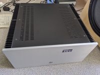
BGW 6500

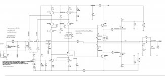
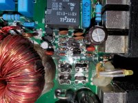
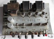
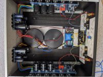
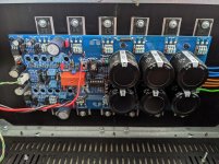
Ok here’s my issue, I recently picked up a BGW proline 6500 free from a guy I bought a pair of subs from. He told me that it was his brothers and one channel wasn't working. Not a big deal I thought as amplifiers are pretty simple at times. I figured I could tinker with it off and on or at least use it as a parts machine for my proline 6000. So I popped off the cover, saw the few components that looked questionable. Plugged it into the variac and slowly brought the voltage up.

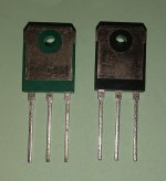
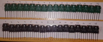
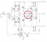
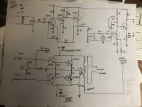
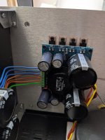
10 ohm resistor started arcing, and 150 ohm started smoking. No problem. Traced it back and a 3773 output transistor was shorted. Replaced both on that driver replaced the resistors. Seemed fine. Looked over the rest of the board found a 100 ohm resistor down on the drivers driver between base and emitter replaced that. Checked those transistors, they tested good.

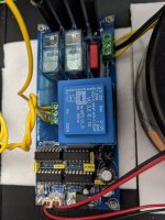
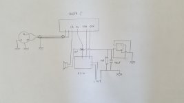
So here is the problem. That channel is messed up and I can't figure out why. It amplifies, at low volumes its fine. Perfect response both channels the same. At medium volume the distortion starts. It sounds like the power supply is running at 24 volts not 60 only on that one channel. I thought it could be a supply problem but the other channel is fine. And I’m getting (+) and (-) 60v against the common rail

Like I said this is perplexing me. It works mostly until there is a demand for power then it runs dry. I can plug it into the mains directly now. Left it idle for about an hour keeping an eye on it. Nothing is getting hot on either channel. I have no idea at all what to check next

Cathode follower protection

I am making a small guitar buffer / preamp using a 12ax7 in cathode follower mode. The high voltage from the cathode is kept out of the signal output by a large capacitor , but there is always a possibility that capacitors will at some point fail , so I'm wondering if there is a simple way to protect the input of whatever the preamp gets plugged into . I suppose two caps in parallel would be one way provided there was some indication of one cap' failure , are there any other simple fuse / trip bits of circuitry that could be applied?

Wavelet measurments

Shared album - lance bartlett - Google Photos
An externally hosted image should be here but it was not working when we last tested it.


Having taken a wavelet of the horn speaker I'm working on (2 way, crossover 800hz LR 12db/oct), It shows 2 'lines' for the compression driver. Is this a reflection? If it is, what distance is it? for 12ms I come up with 13ft (ish),but that doesnt seam right?

Proco RAT Clone doesn't work

Hello!
This is my first post. I made a lm386 mini amp as my first project and I just began my second project to create a clone of proco Rat.
I chose the schematic from electrosmash.

ElectroSmash - ProCo Rat Analysis
I recreated the circuit on a breadboard but it didn't work. So after a lot of tests I found that if I connect the input to the pin 6 there was an output and the Volume and Tone knobs were working. So the Clipping stage doesnt seem to work. Checked the Voltage between the 7 and 4 pin and its a little less than the battery Voltage (because of the 47 ohm resistor connected to 9v Main).
Can anyone help debug this circuit?

Sansui au-717 grounding issue

Hi.
I been taking over a au717 for a while ago. And it was
In pieces and IT was missing some parts. Im not 100 % sure where the ground wire should connect and go.. There is a metal piece by the output modules. .. Spessially the cables from riaa ground. Dont want ground loop.. Tone control selector board and input RCA. Do someone has this modell and can send me pics or some thing. Maybe not a big issue but when sheild mounted i have hum on the Channel active. Almost gone when RCA is connected. Maybe IT is normal.. Changed all caps. Thanks for help 😎😎😷🤔

A DIY mini monitor which sounds better than the KEF LS50 might be?

Hi Gents,

There is pretty widespread agreement that the KEF LS50 monitors are a truly outstanding commercial mini monitor. I wish I have had a chance to hear them but I haven't. For those of you who actually have heard them, have you ever heard a small DIY 2 way which you felt sounded as good or better OVERALL than the LS50s? Knowing the ingenuity and expertiese of the DIY community, it is hard for me to believe that one or more designs haven't been built which can better this 12 Liter, $1500 2 way, which sports a 5.5" woofer and dome tweeter. I know that "sounds better OVERALL" can be criticised for being vague and subject to listener tastes and prefferences, but I think it is an intuitive and generally useful standard for comparing any two speakers with each other. So, for those of you who have heard them, what is your judgement of the LS50 versus top quality DIY mini monitors?

Best,
​​​​​​​Jay

PMC TB2 Mod

Hey all,

So I picked up a pair of TB2 clones for almost nothing on eBay a few years ago. While I don't generally agree with the cloning thing, especially with a smaller company like PMC, it was just someone's personal project and they were too cheap to resist. I already have another pair of real ones, and they measure perfectly against them so they've done a great job. I believe the crossover and drivers came out of an original, and it was just the box that was cloned.

I've had them as my living room system for a while, but one of the metal domes is caved in causing a 2k peak with a dip further up. I pulled it out with some tape, but there's still a little dip and it doesn't sound quite right. As they're kind of a donor set anyway, I was thinking of experimenting with them a little.

From what I've read the "TB2i" version uses a lower crossover point and the Seas 27tdfc soft dome. As I'm not too keen on metal domes anyway I thought it might be worth dropping a set of these in just to see how it sounds. As far as I can tell, the sensitivity and impedance are exactly the same as the originals, but is there anything else I should look out for that might cause an issue? Possibly a different phase response? As far as I can tell the originals were Tymphany D25AG-35.

Alternately I'd really like to try out a set of ribbon tweeters in them, but I can't find one with similar specs.

Would love to get some input from you guys.
All the best,
Blindmelon7

Minidsp going bad? Wiring? Help

So I powered the minidsp equipped boombox I built up for the first time in a few days and tried to listen to some music, and it sounded harsh and grating. When I listen to this system, I normally want to turn it up, but this time I wanted to turn it down. It wasn't super obvious, if I was listening to music at a lower volume while doing the dishes, not really paying attention, I probably wouldn't have noticed. I listened carefully to figure out what was actually causing the harshness, and it's a bit hard to describe what exactly I heard but I'll try my best. I could hear all the detail in the music, the general picture, but in the background it was almost like certain frequencies were resonating again after being played. It's like someone tried to mix in a little of the audio feedback you get when you point a mic at a speaker. The best way I can describe it is the sound you get when you plug an aux cable in improperly into a stereo, except not as obvious. I also noticed that it only seemed to come from the tweeters, both of them. I confirmed this by switching the woofers off. It's a two way system. I tried eliminate what I thought could be a problem, if I'm missing anything maybe someone could let me know. First, I eliminated the source itself by playing the same music on my other systems and seeing if I heard the same thing. I didn't. Next, I eliminated the tweeters by disconnecting them and connecting a coaxial car speaker I had lying around. Still heard it. I then eliminated the amp by disconnecting it and using the amp for my bookshelf speakers instead, I still heard it. I'm not really sure what else it could be, I checked that all the cables were plugged in correctly, and I don't think they fail that easily do they? How likely is it that it's the minidsp board? I assumed that since its a digital device it's the least likely to screw up the sound, but I think I've eliminated anything else. It's possible I might have knocked something lose accidentally as I've been trying to install some amp meters, but I'm generally careful and can't remember any instances of that happening.

kicker kx300.4

got kind of a strange problem i have the protection light on the channels are labeled as amp 1 and amp 2 amp 1 works amp 2 does not but when i turn off the switch powering the remote power it will work for a second or two same when i flick it to on sound will come out briefly then stop and if i do the same on amp 1 it seems to get louder like more power but will still continue to function im thinking maybe a capacitor problem but really i have no idea where to start to track down the fault

Accurately Measuring Line Arrays?

Haven't figured out why this pic is upside down but life goes on!

attachment.php


Anyways, I've been hanging around the REW support forum on AVNirvana because I was assuming my 'strange' line array measurements were as result of me missing something on the steep REW learning curve. After poking around some more and continuing to read I'm starting to think my answers lie here. My first clue was reading Dr. Griffin paper where on page 5 he points out that nonlinear impulse responses are an inherent problem with line arrays.

Also, I came across another another possible great observation listed here,
Wave-front shape and impulse response: spherical, cylindrical, plane-wave

My experience is that it is very difficult to get accurate in-room measurements of the array. You simply see a lot of interference, which results in a smeared impulse response as well as a very ragged amplitude response with lots of peaks and dips. Move the mic just slightly and the response at higher frequencies tends to change a lot. What I do, is I take lots of measurements and average them. I EQ based on this average.

Earlier you said you could run some simulations. I'd love for you to do that. Would you please show the impulse response of a near-ideal array (with infinite or very long length and with densely packed point-sources), both with and without 3dB/oct. highpass? I'd also very much like to see what the effects of an increase in driver spacing are. I doubt he impulse response of a real-world line-array such as my own can be fixed by means of a simple high-pass filter.

The quoted portion in bold speaks volumes to exactly what I'm experiencing!

All that said, I have a new MiniDSP 2x4HD and my goal continues to be 'enhancing' my listening experience with a few well chosen EQ filters and possibly some FIR filters.

The journey continues!

Regards,
Dan

Attachments

  • MC-fixed.jpg
    MC-fixed.jpg
    72.2 KB · Views: 522

X= 0.5 Matrix SSS?

Elias hasn't updated the web page sense 2013, and to my knowledge almost nobody built a pair. I've been wondering about this ever sense.

http://elias.altervista.org/html/SingleSpeakerStereo.html

Im thinking 2x FaitalPRO 5FE120, and I have some SB Acoustics SB21SDC tweeters that I can use for the project...

The idea is to make the 5' woofers sealed, and to eventually cross-over around 200hz to a dedicated subwoofer.

What do you guys think?

Substitute FETs

Since I am just getting started with amplifier repair I don't have much on hand in terms of replacement parts yet. Can anyone provide guidance or suggest some reading materials for selecting temporary MOSFET substitutes for testing purposes?

My question is more focused on FETs in the power supply section since finding substitutes for outputs is a crap-shoot and I'm not nearly experienced enough for that.

For example: I have a RF P300-1 with blown HUF75344G3's. I don't have any of those but would like to test the output section and order all the parts I need (plus extra) at once.

The N channel FETs I do have on hand are IRF3205PBF and IRFZ44NPBF. Are either of these an adequate choice for testing and what specifications should I be looking at to make an informed decision?

Thanks!

Irs21844s driver board problems

Hi I have an incriminator audio ia 40.1 amplifier. I have replaced all the driver ic's (irs21844s) and I have my low side drive were it's supposed to be. I also have all the proper positive rail voltages and negative rail voltages were there supposed to be. I installed the mosfets, 1 per bank to test it and it blew 6 of the 8 fets. It seems like it dumped the rail caps into those fets. Any help would be much appreciated

Tannoy Diaphragms - Tulip Style

Hello all.

I recently grabbed 3 Tannoy 15" drivers, possibly 3833 or similar. Unfortunately two of them have blown high frequency diaphragms. :bawling: 
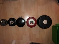
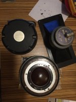
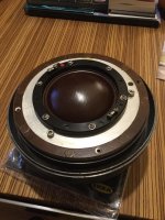
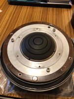
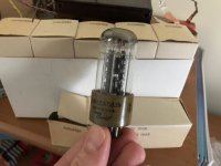
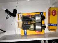
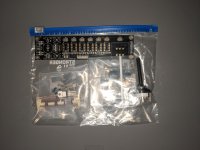
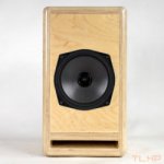
Noticed the diaphragm is NLA but was wondering if there was a way to repair them. Look to be the 7900 0550 type but I may be wrong.

The whole setup was too good of a deal to pass up but I couldn't test them due to SpeakOn connectors. Got 3 Tannoys, 3 TC Sounds LMS 15" subwoofers, and a single TC Sounds LMS 5400 18" sub. Out of everything, there's 2 blown 15s and 2 blown Tannoy diaphragms. Are the voice coils in the subs repairable as well?

I've refoamed countless drivers but that's the extent of my speaker repair experience. Had to sell my Tannoy Golds to help fund a business purchase and have been on the hunt for something similar since. Any help would be greatly appreciated.

Parts for 8audio EL34 Jadis JA30 build

Hi all.

I am quite new with tube amplifiers, but after i built my pre-amp i am ready to go into more advanced builds. I came across the bare PCB's at 8ball and decided to give it a go. Unfortunately i am not quite certain where to look for the transformers and chokes.

The system consist of follow two boards:


8audio was so kind to tell me which specs to look for:

For the power transformer, the requirement is :
2nd output :
310Vac 0.4A (For diode rectify); or 340Vac 0.4A (for tube rectify)
6.3V 5A x2
15V 3A
12V 0.3A (optional for use of high volt supply delay pcb)
5V 5A (For diode rectified power supply pcb only )

Choke
1.3~3 H 1A

Output Transformer:
Rating: 30W~50W
1st input: 5.5K with ultra linear tapping

So my questions are:
  • Where do i find the transformers for european voltage (230VAC)?
  • Should i go for a tube or diode rectified PSU?
  • Should i be aware of anything when i choose capacitors and resistors (quality and type?)
  • Can i use toroidal instead of traditional transformers?

I hope this help also helps other people trying to build a system based on the 8audio benefit from the replies.

Thanks in advance!

Magnavox/Collaro S600 Mounting Board

I have a vintage Magnavox console I've posted about here recently, and have come to like the original S600 turntable so much I purchased a second one to put in a vintage changer I have that needed a table. Unfortunately I didn't realize until I'd had it a while that it was missing the mounting board; is there a resource around where there are templates available for various turntables and their mounting shape? I obviously have one in my console but am trying not to pull that table out unless I have to.


I work in the graphics industry and had the idea that it might be worthwhile to redraw and then create printable versions of some of these if I could get to-scale scans of original boards, FWIW - just a thought, if that doesn't exist somewhere already.

Bad crossover or amp ?

Hello


I made some very simple amps, just for learning. When i used them with my speakers (tweeter and woofer) the sound is low, tweeter almost makes no sound and no vibrations, almost all from the woofer so it doesn't sound very good, voices sound deeper,unnatural.
I thought the caps died, tried changing with 4.7uF instead of 1.8uF that were in the speaker, almost no difference same sound.

Tried putting 330uF electrolytic polarized (I know I shouldn't but i didn't have non polarized) and tweeter was noticeable now, much better sound, cleaner higher notes. I know that lower frequencies are being passed through the cap, but without it it just sounds bad, isolates almost everything.


TLDR: Tweeter almost made no sound(only the woofer), replaced 1.8uF with 330uF, much better sound, don't know is the crossover bad or my amp, and could the original amp have been made specifically for the speakers so they sound good together ?


The crossover is only one 1.8uF np cap.


Thanks

Mark Levinson 336 strange ticking

Hi everybody, in last few weeks I’m hearing a strange ticking from inside of the amp. It happens after about an hour of use and continues after the unit is off for 20 minutes. It’s quite regular every 30 seconds, not very loud, but without music it’s easily audible.
Music is played normally without distortion or noises. Do you have any suggestions ? It’s seams a relay but everything works fine til now.
Thanks for your help

TPA3255EVM to complete amp (advise needed)

Good day all,

I am new to the forum but it seems that there is a wealth of information to be had here 🙂

I was looking for a good set of 2.1 desktop speakers/amp but unfortunately high end models like the corsair SP2500 is not available in my country and importing it via the likes of amazon will work out more than double the list price when taking shipping and taxes into consideration.

That's when I thought that I might take my first step into the world of DIY audio. I can get my hands on the TPA3255EVM (TPA3255 325W Stereo/ 600W mono PurePath Ultra-HD Analog Input Power Stage Evaluation Module - TPA3255EVM - TI Tool Folder) for $250 converted when it releases and figured that might be an ideal place to start if I can buy some descent bookshelf speakers for a quality 2.0 setup.

I am by no means an audio expert but I have degree of experience with electronics in general and I was hoping someone on the forum could help me with the following questions:

1) What do you think of the TPA3255DDV specifications? I reckon I will drive 2 x 100 Watt, 8 ohm bookshelf speakers so I will stay well below 1%THD+N. Do you think it's good value at that power and distortion level considering the Class D amp can get away with a much smaller PSU? Or are there commercial options that are better value(I have not seen any)?

2) What is a good PSU to use for this amplifier? Would something like the SP-750-48 (http://www.mantech.co.za/datasheets/products/SP-750-MW.pdf) work are switching mode PSUs a very bad idea for audio amps? Ripple noise is listed as 120mVp-p max which is a very small % at 48V, but information regarding the switching frequency is not available so I am not sure if anything will fall within the audio band. Where can one buy stand-alone low noise linear amps? They seem to almost non existent.

I do have some additional questions but those above are the ones that will determine if proceeding with a project like this is even worth while.

Your input on this is much appreciated 🙂

LM3886 build snag...

Hi there,
So, here’s my story in a nut shell... I was excited to build an LM3886 chip amp, found a BOM and ordered everything on the list a little over a year ago. A little while later I found a PCB set so I bought that as well. A few weeks ago I was able to find time to begin the project. I had nearly completed the aluminum case work when I thought it would be a good idea to populate the tiny amp and power supply boards. This was the first time I actually had a good look at all the parts and components and realized that the some of the parts don’t completely match the chipamp.com amp boards or the diyaudio power supply pcbs I ordered.
Will you help me identify the project and find the pcbs that match the BOM I have?

Thanks for any and all advice

Attachments

  • 4D7B3D4C-A2D5-42D9-B1E7-722CAE4691FB.jpeg
    4D7B3D4C-A2D5-42D9-B1E7-722CAE4691FB.jpeg
    843.2 KB · Views: 315

Spectral DMA-50 distorted output

So a friend of mine cleaned out his garage and gave me this amp. Only problem is that the left channel runs pretty clean at very low volume but gets distorted as volume is increased. The right channel is distorted all the time and has very low output. Any ideas where to start looking. The boards seem pretty simple but I have no expertise and no schematic so looking for any advice.
BTW, there are a grand total of 6 electrolytic caps in the entire amp: 4-330uF caps on the driver board and the two big ps caps
TIA

MCM Electronics closing?

I read this little blurb on my home town local news site (WHIO) today. I'm not sure of the size of MCM or if they have other locations, but it sounds like they are folding their tent although the article never said this explicitly.

"MCM Electronics Inc. will lay off employees at its corporate office located at 650 Congress Park Drive in Centerville, and at its distribution center located at 405 S. Pioneer Blvd. in Springboro. Both facilities will also close, according to a WARN notice sent to the Ohio Department of Job and Family Services."

Audiolab 8000M gone dead

Hi all,

I have up to now been the happy owner of an Audiolab 8000Q+M setup. Probably not the most modern setup anymore but I like it very much. The M:s seem to be the original design (the PCB says "issue 1).

However, one 8000M went dead on me the other day. No recall of abuse (whatever one could make of that statement - rather, I haven't abused them 🙂 ).

I figured to have a shot at fault isolation, but my electronics skills are regrettably limited. Since I have two and the other one is fine, I thought I could measure and compare between them, and whatever difference I found would be the culprit. But now I don't quite know, definitely found differences but what is cause and what is effect...? Anyways, this is what I know:

When turned on, the red LED comes on, and the relay clicks after a plausible delay, about same as the other one. But the output is totally silent, can't even hear hiss.

Measurements power on:
1. Measured power supply voltages. Same on both, all the way to the output transistors. +- 52V.
2. measured base-emitter voltage on the output transistors (sanken 2SA1216 and 2SC2922). 0,6V on the good one, 0V on the bad one. So probably something dubious here but what would be the fault behind it?

Power off:
3. measured the internal resistances in the output transistors. Same on both amps.
4. measured back upstream the signal chain until I got to Q114 transistor (marked with A1209, googled as a Sanyo type apparently) and the emitter-collector resistance was very different, approx 24Kohm on the bad one and inf on the good one)

Anybody got any ideas? I would greatly appreciate any hints.... I don't intend to use the forum as an online repair shop, but I'm afraid it will have to be a DYI fix or a trip to the supermarket for a substantial downgrade... And if I can learn something along the way, I'd be fairly happy anyway 🙂.

Have a nice evening, best regards Jon

Fixed attenuator before stepped

Hi Pals,
I have an amp with input sensitivity 1.2V amp with 26dB gain,that will drive an 8Ohm speaker with 100Watts.
My stepped attenuator is 10K with 23 steps starting at 46 dB down to 1db attenuation in 3dB STEPS.
My full range speaker is only 50W peak power rated and I do not want to overdrive it even if someone inadvertently turn the dial up to 1dB attenuation.
Will it be possible to use a fixed attenuation stage before stepped attenuator?
Will it affect input device by any means as I assume the impedance of attenuation stage will be halved ?

FS: tubes, 26, 76, 78 and others

tubes for sale, NOS. I live in Poland, EU.
Price per 1pcs

Minimum order value - 100 EUR / 120 USD

I need to check how Post offices are working nowadays, so shipping info has to be confirmed.

26 type, 76 type, 78 type, 5x4g - 25 eur / 30usd
6c8g tung sol - 35 eur / 43 USD

E182cc quad Philips - 100 EUR

Attachments

  • IMG_8178.jpg
    IMG_8178.jpg
    557.5 KB · Views: 145
  • IMG_8179.jpg
    IMG_8179.jpg
    535.4 KB · Views: 146
  • IMG_8180.jpg
    IMG_8180.jpg
    515.4 KB · Views: 137
  • IMG_8181.jpg
    IMG_8181.jpg
    472.3 KB · Views: 136
  • IMG_8182.jpg
    IMG_8182.jpg
    503.3 KB · Views: 137
  • IMG_8185.jpg
    IMG_8185.jpg
    730.2 KB · Views: 87
  • IMG_8184.jpg
    IMG_8184.jpg
    740.1 KB · Views: 88
  • IMG_8183.jpg
    IMG_8183.jpg
    528.4 KB · Views: 78
  • IMG_8190.jpg
    IMG_8190.jpg
    551.6 KB · Views: 84

Building C830 Center Channel to match Boston Acoustics T830, T930, T1030

History:
I own a T830 pair that I purchased in the mid 90's. I've had them in 4 different homes and at least 6 different rooms. I originally drove them w/ a Yamaha RX-300 receiver, then later w/ an Adcom GFA-535, and now currently w/ an Adcom GFA-2535 as LR of a HT.

I have always loved their reproduction of mid-bass up thru highs, but they lack low extension. I resolved this by adding an M&K MX-200 to the HT a few years ago and crossing them over at 80 Hz. In an effort to build out the HT, I tried a Velodyne CHT Front Row center channel for a while. And although the tweeter was close to the CFT 3, it was not the same. I eventually replaced the Velodyne w/ a CenterSat7 and have been using it for about 3 years.

Current State of my HT:
L/R are Boston T830, Center is Boston CenterSat7, Surrounds are Velodyne CHT Front Row satellites, Subwoofer is M&K MX-200. Receiver is Marantz SR4300 (used as pre/pro, and amp for surrounds). Amplifier is Adcom GFA-2535 in three channel config to drive L/R/C.

Issue:
I’m not happy w/ the CenterSat7 for a few reasons. First and foremost, the mids do not match the mids of the T830. There is no smooth transition across the sound stage. It does not present any portion of midrange (majority of vocal information) as well as the T830. Secondly (and I know that I’m being picky) design philosophies of early Boston products were completely abandoned. The enclosure is constructed of plastic, the grill not acoustically transparent, and it is bass reflex via passive radiator.

Project:
Build a C830 using drivers, cross-over and binding posts from a T830. The new enclosure needs to fit on my TV stand below the TV and not block any IR remote sensors. It will be made of MDF w/ finish to be determined. Original grill will be used, if possible, to cover the woofer. I will attempt to keep the vertical alignment of the drivers. The enclosure will most likely take the shape of a short inverted T with the mid and tweeter mounted to a ‘sail’ sticking up from a woofer cabinet. The woofer cabinet will be taller in front than in the rear to accommodate the 8” woofer, but still fit between the bottom and middle shelves. It will be braced internally in the same manner as the T830.

To date I have acquired a ‘donor’ pair of T830’s, ordered replacement surrounds for the woofers, and reviewed a pencil sketch w/ a carpenter friend who will help w/ the cabinet construction.
Photos, trials and tribulations to follow. I’d love any advice that veteran cabinet builders have to offer, especially when it comes to center channels. Has anyone else cared enough to undertake such a task?

Primo EM182/EM282 alternatives for Ambisonic mic

Hi all, this is my first post DIYAudio and I'm excited to have discovered a like minded community!

I'm currently working on building the open source first order ambisonic microphone as described here and have been having difficulties sourcing the Primo EM182 (or the equivalent newer EM282) from Primo at a reasonable price point. Micbooster has the 182s for around $35 each after international shipping and taxes, which I'll just go for if I can't find anything else, but I was wondering if anyone knew of any other good capsules or capsule manufacturers for cardioid electret mics meeting similar specs? (size, snr, operating voltage) I already gave Primo a call and they don't seem to want to sell to hobbyist's directly.

Thanks!

Radiomatic Master II Stereo amp Schematic

Does anyone have any idea where I can get some info on a Radiomatic Stereo II {2} tube amp. trying to troubleshoot a power supply problem I believe. All filter caps have been changed, diodes check ok, and replaced 1.5 k resistor that was way out. Can't find much on line possibly made by GE? Circa 1965 stereo PA amp supposedly. Was in a cabinet with a turntable like an early DJ setup. Thank You in advance

Attachments

  • master_ii_stereo_1082676.jpg
    master_ii_stereo_1082676.jpg
    29 KB · Views: 77

FS: Pair of Hammond 1640 SEA Single Ended 30W

Hi there,

I am selling a pair of brand new/ unused Hammond 1640SEA.
These are 1.25K primary and 30W single ended.
Bought them a year ago and never got the chance to build anything around them.

I am asking $160 firm plus shipping of a 25lbs box from 06851.

Thank you,
Radu

Attachments

  • IMG_5771.jpg
    IMG_5771.jpg
    608.3 KB · Views: 261
  • IMG_5772.jpg
    IMG_5772.jpg
    620.8 KB · Views: 259
  • IMG_5773.jpg
    IMG_5773.jpg
    562.8 KB · Views: 252

Altec 1591A Output Transformer questions

I have been going through a bunch of these line amp/comps lately. A couple for a friend and couple for myself. I really like this unit.

They all needed various mods and refurbed.

I decided to breadboard the preamp only portion to get a better feel fro what is going on. I am not familiar with SS split load Push Pull setup, I am with valve though, so it seemed like a cool tinkering project.

I don't have any of the original AL2712 npn transistors. And I don't have any 2sc2545/s that I see using as a Sub.

I do have a bunch of 2N3392's. And some 2N3053's. So i figured, I'd plop em on a board.

I am using an altec mic to line on the input side and just testing with a shure 57.

I knew I would have trouble getting specs for the output transformer. Or at least I'm under the impression that they are hard to find. So I figured I want an output transformer for low z primary and 600ohm secondary???

I have an edcor XS-1100 here at the house so, I figured I'd try that.
I do realize that the tertiary NFB won't be there, so I just ran a cap in series with the collector load of one of the 2N3053's. With a stock value of 27K feeding the emitter like in the schematic. I realize that this may not reflect the actual NFB being applied by the Stock OT, but it's in place and is working.

I only built the preamp portion of this circuit, the sidechain/LDR circuit is not present.

Basically with a 12VCC supply everything looks good crossed with the schematic, with respect to DC voltages.

OK, here is the problem.

I have the edcor XS-1100 set up, and I think it's terminated properly for the load which it's feeding. An audio converter going in to a +4 line input on the unit.

I'm not getting near the level I would get with mic plugged into the ACTUAL ALTEC units. So something ain't right?????

I will start AC analysis, I did put a 1v 1K sine wave in the front end and found I had a good buffer plus a little gain after (Q1,Q2,Q3).
Coming out of Q5 I had a reduced AC voltage. 1/5th or so. That can't be right. With the NFB lifted it was closer to input voltage. I may have something wrong here.

Schematic attached and my hack-reduced schematic for review.

Thanks,
joe

Attachments

  • Altec-1591A-CompAmp_Page_8.jpg
    Altec-1591A-CompAmp_Page_8.jpg
    561.4 KB · Views: 349
  • IMG_1566.jpg
    IMG_1566.jpg
    707 KB · Views: 241

NAD 3020 as separate phono stage

Dear All

I experimented with several separate phono stages, yesterday my bro took his NAD 3020 to my place. Just for fun, we took the signal out from the tape output to feed the line stage of my Audio Research SP9 Mk II

... I was shocked! The sound of my loved Shure V15 was too good to believe. Although I missed some of the fresh touch of the SP9 in the mids/highs, although the overall presentation is not as clean as from the SP9, the energy and realism of the NAD output is quite something.

I decided I want to experiment a bit further. So I'd like to modify the signal path to avoid the tape loop. I want to put a pair of RCA connectors on the back and take the phono output from an optimal location in the circuit.

I wonder whether this has been tried before. Any experience to share?

Classe CA-300

Hi Everyone,

I'm hoping someone might be able to give me some direction on fixing a problem with my Classe CA-300 power amp.

In short, the amp mostly works fine, and it will sometimes stay on for days (I always leave my SS gear powered on), but sometimes it goes into protection mode, as indicated by a flashing green power light. The amp has been operating this way since I got it used two years ago. I can consistently get the unit to pop into protection mode when first powered up if it hasn't been used in a day or two; after the first power cycle / protection, I can restart it and it will operate.

I'm am completely certain the issue is contained within the amp, as I own numerous components (high end amps, preamps, speakers, and cables) and the behavior is the same no mater what gear is connected to the amp.

A Tech buddy of mine originally thought the problems were related to the input stage, and replaced the input opamps, as also changed the input relays. Bias and DC offset have been adjusted in accordance with the service manual.

Due to the challenges of shipping this unit (no box, and 90 lbs weight) I don't think it's economically viable to send this to Classe for repair.

I'm just about ready to sell this unit for parts, so any thoughts or ideas would be appreciated.

Thanks,
Trevor

1500$ home Hi-Fi System DIY

Hello everyone 🙂 🙂

I play guitar, I like rock music, most of all Pink Floyd, Whitesneake, Dire Straites, Al Di Meola.. 😎 😎

I would try to create a DIY sound system for my house. The system would be consisted of 2 x towers, 1x center speaker for front and 2x bookshelf speaker for rear.
I think a good combination for towers would be a 3x8 '' full range speaker, 1x bigger and 1x smaller tweeter. For the center would be 2 x 8 '' full range and 1 xbigger tweeter. And for bookshelf would go 1x smaller tweeter and 1x 7 '' full range speaker.

All 8 '' speakers would be: Dayton Audio RS225P-8A 8" Reference Paper Woofer 8 Ohm
All smaller tweeters would be: Dayton Audio AMT Mini-8 Air Motion Transformer Tweeter 8 Ohm
All bigger tweeters would be: Dayton Audio PT2C-8 Planar Tweeter
All 7 '' full range speakers would be: Dayton Audio ES180TiA-8 7" Esoteric Series Woofer 8 Ohm

Now I'm interested in the following:
I'm planning to buy everything from partes express site, I'm new to this so i'm interested in the following
1) what DIY amplifier modules do I need to take for my system? I guess I need one towers amplifier and one for the center and bookshelf speaker. Can you recommend which modules would be best for this?
Audio Amplifier Boards & Modules - Parts Express

2) What are Dayton audio speakers in quality, is it worth investing $ 1500 in a system that will be made up of that company alone?

3) Is this DSP good for my whole system?
https://www.parts-express.com/dayto...nal-processor-for-home-and-car-audio--230-500

4) Can you tell me if I need a special 12 '' bass woofer for my system or will this speaker combination cover the bass enough?

5) What crossovers do you need for tower, center and bookshelf speakers, if you could send a link, because I don't understand it.
1) https://www.parts-express.com/dayton-audio-xo3w-700-56k-3-way-speaker-crossover-700-5600-hz--260-156
2) https://www.parts-express.com/dayton-audio-xo3w-500-4k-3-way-speaker-crossover-500-4000-hz--260-152
3) https://www.parts-express.com/dayton-audio-xo3w-625-5k-3-way-speaker-crossover-625-5000-hz--260-154


I'm very good with a soldering iron and can work with wood, so none of this is unfamiliar to me, I would make a solidworks model of every speaker before, copy some famous companies and make good models, I don't worry about that. 😀 😀
What bothers me next is, is it better to spend $ 1500 now on this DIY project or buy a ready-made $ 1500 system that works better? 😕 😕


I ask for recommendations and advice 😱 😱

  • Locked
Need help on tele-tech magazine article

Hello everyone,
I desperately need some help. Does anybody have the copy of "Tele-tech/Electronic Industries" magazine july 1962 issue? I have downloaded this issue from americanradiohistory.com, but the main problem is that there is missing page from 115-118, 116 and 117 no pages are missing. That article is very important for my project and the main 2 pages that describing the circuit diagram are missing. So if anyone in this group luckily have the 1962 july issue of tele-tech/ Electronic Industries without a missing page, please let me know.The name of the article is"design information for regulating and stabilizing HV power supplies" by donald O. Ward.

Thank you all

Can someone double-check my opamp FB theory?

In the top diagram, is the basic input of an Audiosource AMP100, which is designed for +4 dBu pro level. The first thing the signal hits is an opamp configured as a voltage follower. (Unity gain.) If I want to convert the input to -10 dBV consumer level, is it as simple as adding the feedback circuit in the bottom half of the diagram? I have it set for a gain of 11, which is close enough to the 11.79 that I calculated.

Thanks all.
Artie

Attachments

  • AMP-100_input.png
    AMP-100_input.png
    15.6 KB · Views: 327

Pre drilled heatsink for Holton modules.

Could anyone tell me if they have used Holton modules with the predrilled UMS heatsinks available on the the DiyAudio Store ?

HPA-NXL300 R4 – Holton Precision Audio

It would make casing up a project much easier if the hole spacings match the spacing of the transistor holes.

I am interested in upgrading my 20 year old Audiolab 8000M amplifiers.

help wiring Quad-gang pot for stereo crossover

Hello guys, i'm building a stereo crossover from Elliot Sound products
'Isolator' Equaliser


I'm not totally sure hot i have to connect the 2 quad-gang potentiometers which allow me to switch the crossover point. (2 sections of a pot will control L channel, the other 2 will control R channel)

I picked 2 of those dentent pots
https://www.mouser.it/datasheet/2/54/ptd90-777943.pdf


Attached you can see how i would wire it. do you think is correct?
i attach the original schematic from ESP as well.


thanks for any help🙂

Attachments

  • 94387611_254505765675450_6699894122695622656_n.jpg
    94387611_254505765675450_6699894122695622656_n.jpg
    130 KB · Views: 88
  • Schermata 2020-04-25 alle 18.02.07.png
    Schermata 2020-04-25 alle 18.02.07.png
    34.2 KB · Views: 95

UGS Power AMP

Need space for new project therefore selling this Amp :

https://www.diyaudio.com/forums/pass-labs/108683-ugs-power.html

Perfect working condition, asking 1000 Euros + shipping which will be high due to weight ...

Attachments

  • Gehäuse.jpg
    Gehäuse.jpg
    335 KB · Views: 191
  • AMP_oben.jpg
    AMP_oben.jpg
    467.9 KB · Views: 190
  • Gleichrichtung.jpg
    Gleichrichtung.jpg
    282.1 KB · Views: 189
  • Einschaltverzögerung.jpg
    Einschaltverzögerung.jpg
    302.4 KB · Views: 190
  • AMP_Platine.jpg
    AMP_Platine.jpg
    416.1 KB · Views: 187

Crossbreed of transmission line and bass reflex?

Finnish Hi-Fi company Hifitalo has some DIY designs that incorporate their own (as far as they claim) TransFlex enclosure designs.

I've tried searching transflex, and browsed some resulting threads about tapped horn designs and transflex design, which apparently originally is an older idea that has been patented at some point(?) and that seems to incorporate an inward firing driver(?).

However, I'd like to ask if anyone knows how to calculate these "TransFlex" cabinets Hifitalo uses. By drawings they seem to be bass reflex cabinets with an outward firing woofer, but incorporating inner structure of adjacent chambers of increasing volume with ports in between with increasing port area. Hifitalo claims the enclosures have very controlled bass response and reduced woofer excursion.

Hifitalo is a fairly big Finnish Hi-Fi company that for instance is the official importer of Seas drivers in Finland. Hifitalo also bought an established Finnish loudspeaker company OR and continues their manufacturing with some very good results. I've also heard one of their DIY designs incorporating the "TransFlex" (Aw-3 Alu https://www.hifitalo.fi/aw-3_alu_rakennussarja) that sounded really good, especially the bass for that small a speaker. Based on all of this, Snake Oil isn't the first thing I'm thinking.

Does anyone know a way of calculating this kind of enclosures consisting of adjacent chambers that have ports between them? By intuition I'd imagine they might be essentially transmission lines or horns or derivatives thereof.

In the next posts I'll link a few of these designs I'm talking about. Hifitalo has descriptions (or actually marketing speeches) for the designs in Finnish, but I think the detailed blueprints speak more of the actual designs, so I'll link the blueprint PDF's. Every enclosure is supposedly designed for a specific speaker (or a specific woofer), so I'll include driver name and any essential info provided (as well as the original sales speech page as a link as well).

MTX Thunder Elite 1501D

Bought this amp knowing beforehand that it didn’t have no output. Upon getting it on my test bench I confirmed it had rail voltage and the plus and minus regulated voltage. I checked the outputs and there were no shorts. I replaced both A3120 optocouplers and both NE5332 opamps. Upon replacement I had rail to rail oscillation on the outputs and produced clean audio on the bench. Upon installation in a vehicle and setting the gain on the amplifier I got full voltage on the speaker terminals and a deformed square wave. Removed the amplifier from the vehicle and installed on my test bench and couldn’t replicate the issues in the car until turning the gain to the max. I’ve repaired a few MTX’s but never had this issue before.

6J1 Preamplifier: Rythmic Popping Noise

Heya,

I searched high and low to see if I could find the exact issue I'm running into with the exact kit.

I've assembled the China 6J1 tube preamp that's a fairly popular DIY kit. I've tried everything that I can think of, but I cannot get it to function 100%. There's a rhythmic popping noise that comes through the speakers. I turn the preamp on, everything's fine (music comes through perfectly), but after around 10 seconds, there's a POP, POP, POP noise that starts up and never stops. The noise is constant, regardless of where the volume knob is set. Oddly, the popping cadence increases slightly the higher the volume knob is turned.

The power adapter is AC 12v 1200mA, right on the money. I've already tried replacing both tubes and re-flowing all the joints. Nothing is helping, and there is no change in the behavior.

I'm at a loss. Do you have any ideas as to what may be causing this? This is my second DIY kit so I may take some moments to get the right info for any followup questions you might have. Thanks!

diy impedance match (and pre-pre amp?) from phono cartridge (MM) to mic pre-amp?

Hello Folks

First post - I joined 10 years ago and every so often I end up back here for an answer - but, this time I can't find an answer. Please bare in mind I can just about remember Ohms law and understand a capacitor but when it gets all wiggly I tend to get a bit confused...

I see this topic crops up across the net and here every so often: why can't I use a mic pre-amp with my turntable? I know there are reasons why not - RIAA, impedance mis-match, capacitance mis-match, level mis-match.

I've read some discussion about the merits of pre or post pre-amp RIAA correction - but, to use the mic-pre amps I will be using post-pre amp software RIAA correction.

Requirements:
1) Impedance match from 3.7KOhms to 47KOhms;
2) Capacitance (variable?) match to present between 200-500 uF to the cartridge;
3) Balanced;
4) Possible amplification (5 mV MM Cart to 10mV Mic - What's that in db...?);
5) If amplified, then phantom powered.

The mic inputs I'm trying to drive take a minimum input of -45dBu for max output, which my 4mV cartridge will just/ almost meet according to analog devices db conversion tool - but, it's not good to drive an amp at maximum - or is it?

I first looked at this:
Phono Transfer System Bare Flat Preamp PC Boards
Following a discussion on using a mic amp for a phono cart here:
Mic preamp as phono preamp? - Gearslutz
So I assumed it was for mic level input, but it's not. It's for line level input and so negates the mic pre-amps I'm trying to make use of, uses up a couple of live level inputs I want for other things and I suspect it's rather more amp than is necessary.

I then found these:
Groove Sleuth Adaptors
At the other end of the spectrum - they're very expensive and I suspect are nothing more than an XLR with a resistor inside...

So, does anyone know of a diy project that fits the requirements of 1-5 above? Or, any other comment... 🙂

(Also, have I posted this to the best forum - there's so many on this site!)

Thanks for listening.
Morgan

WTB - Focal JM LAB Utopia Be TBU Beryllium Tweeter

I need one Beryllium Tweeter for my Focal Utopia Be speaker. It's a TBU model used on Utopia Micro, Diva or Alto Be speakers. I need one in working condition (whether new or used) without cracks or holes on it. I'm willing to pay decent money for it. Even your tweeter has some small blemish, you can contact me also. I hope can receive your message ! Thank you so much !

Mooly amp, high gain vs Voltage?

I am rethinking the amount of Voltage I shall supply the Mooly amp, Mooly has written 45V-0V-45V as a possible voltage to his great amplifier but I am thinking if it would be of some advantage to supply even more.
I am not doing that to play louder but to have even more power so I can use that amplifier to test and drive future speakers.


The gain is 47 times or 33.4dB, And max input from a CD-player should be 2V
You could say that it's 47 gain X 2V, or 94V, but that sounds insane much to me.

How do I dicide on max voltage and ampere?

LCD Backlight for Rohde & Schwarz UPL?

I just picked up a R&S UPL on eBay for a good price, but it suffered from a shipper that just didn't care if the item made it in one piece to its destination. Some pieces have broken off the case, mainly feet, however the LCD isn't right either. Only the upper left corner is illuminated, the rest is pretty dark and hard to read with lights on in the shop.

I am trying to decide whether to keep it, break the cal seal and attempt repair, or just return it.

When it first arrived, it would not even boot up. After several hours of poking around in DOS, I finally got the UPL software to start up. I also found and loaded a diagnostic BASIC program and ran all tests. They passed.

The issues are:

Broken feet
Noisy fan bearing
Dim/unevenly illuminated display

If that display could be repaired with a new backlight, or replaced entirely with something equivalent but maybe a bit better, I think the instrument could be servicable.

Does anyone have photos of the inside of a UPL? Has anyone repaired the LCD display on this particular unit?

Need help with Pioneer 9100 volume pot

I have a pioneer 9100 that I would love to resurrect, but one of the issues is a broken volume pot assembly

The original has 2 gangs (two with a ground, six in total) with an additional two prongs coming from the bottom of each gang (what are these?).

I was able to retain the first part of the volume assembly and attach a new double gang pot to the back (keeping the volume limiter (0-30-60db), but I don't know what to do with the extra wiring. There are no pots available which have the same configuration as the original pioneer.

I took many pictures, and looked at the schematic, but I'm not sure what to connect/disconnect so that I can retain (at the very least) the main L/R volume functionality. Can you easily tell what the wires do by their colors?

The link is to a folder with some pictures of the pot. I also have some addiitonal photos if these aren't enough10.0.0.0.1 192.168.1.254 hotmail.com

Duntech Thor IB-20 CC crossover

This is an active crossover for the Duntech Thor self-powered Subwoofers circa 1986.
I'd like to move the crossover point (3dB down point) from 110Hz down to 90Hz or so.
I sent John Dunlavy a fax inquiring how to change it to 160Hz (1987), and he sent me a fax of the schematic and some suggestions on what to change, both on the active circuit passthru to the midrange power amp, as well as in the subwoofer's equalization circuitry. He suggested .086uF instead of .1uF which is the value of the caps in both places he told me to change. I forget why I wanted to raise the crossover point, but in hindsight, that's the wrong direction!
I never actually took his advice. Instead, I simply bypassed the active pass-through circuit which drives the power amps [to the mid-range speakers] with a .047uF MIT Multicap (which turns out to be the 3dB down point of 60Hz). (As calculated for a 60,000 ohm input impedance of the Amp).
I lived with that for 25 years. But now I want to also shift the 3dB down crossover point in the circuit which drives the subwoofer down to 90Hz or less.
I began by changing the .1uF cap that John suggested I work with - to a .147uF.
It is indeed starting to shift the 3dB down crossover point downwards but it's also reducing the output at say 40Hz and 30Hz as well by a small amount - 1dB or so. Not exactly the direction I want to go with my bottom Octave! So, I am looking for ideas as to where in the circuit to start modifying the crossover point without reducing the bottom Octave's output at all! I have the schematic and can email it to you, if you need to see it. thanks in advance. -TMack

UK Passive xo people, advise me on buying components please

Hi all,

I'm about to start putting some passive xo's together for my 1st time.(I've always used digital xo's before but want to learn how to do passives for speakers that I don't want to use 2 or 3 amps per channel for)

Can anyone recommend me some cheap but good brands, and maybe a range of component values that will let me buy a few in so that I have a 'parts bin' to hand if I am experimenting.

I don't mind if they are not the 'best in the world', if my projects end up being successful I'd happily buy more 'audiophile' quality ones.

I usually build with pro drivers / compression drivers if that makes a difference to the power handling of the parts.

Thanks for any help,

Rob.

DIY amplifier

Hi guys🙂,
last week I started to design an active crossover an I just finished. Now I would like to create two transistor amplifier boards, one with about 100W@8ohms and the other one with 70W@8ohms, both powered with a toroidal transformer. Normally I find the schematics online and I modify them for my purpose, but this time I haven't found anything😱.
Can somebody recommend me something😕?
Best regards
Ben

mini Streamer/DAC Project Build

Here's a new mini streamer/DAC project I recently completed. It's currently being used in my shop and I'm listening to as I write this. I wanted this project to include subsystems I already owned, but weren't using. For the past year or so, I've been using RaspPis and DAC HATs configured as roon end-points, so I've gotten a fair bit of experience getting these DAC/streamers up and running. But, I wanted something more contained with all cables coming off the back panel rather than 3 sides of most RPi setups. From a software standpoind, I've been a big fan for over a year now of the roon digital audio, whole-house streaming eco-system. This software is a pleasure to use. Once you have your digital library online (NAS), and capable roon server hardware, you're ready to go. Plus, it's pretty painless to configure and get it up and running too. Roon allows you to purchase their customized back-end server, that runs on a variety of hardware platforms. It also has what they call end-points. These are streamers and DACs that play the music from your network. If you build you own end-point (like this project), also available is 'roon Bridge' which will configure the end-point(SBC) running Linux to work with roon Server. Another Linux solution for an end-point is to use DietPi. It offers an option to automatically configure 'roon Bridge' with from a single software selection.

This project is a hybrid of hardware/software subsystems matched to provide a very small footprint that can be used wherever you have an amp, speakers and network access. It can easily be setup using a USB WiFi dongle for access as well, if you'd rather go that route. You'll see how I've mixed and matched the various hardware systems below. Now that I have a fully assembled unit, I thought I would share the project with the DIY community. The following are the individual hardware/software pieces I used and necessary links.

Hardware:

(1) For the DAC I chose a Toneboard (TB) from Khadas. This little DAC is based on the Sabre, ESS9038Q2M chip, and has been designed well, and provides excellent sound for only $99USD. It can be used as a stand-alone DAC with USB, or coaxial input. I'm using the 'generic' version, but I ended up soldering an extended 40-pin header to it as it was a prototype for using their SBC (VIM 2) - which I am not using at the moment. The 40-pin header is not needed for this project.

https://www.khadas.com/tone

(2) As I wanted streaming capabilities, I need to pair the DAC with an SBC that had ethernet capability and USB. I could have used I2S, but opted not to for this streamer. Besides, the USB-in on the TB DAC uses the well-known XMOS chip so you're getting a well-established interface from the get-go. The SBC I chose was the NanoPi NEO2. This little guy has a very small form-factor and works perfectly for this project. It has all the necessary elements required for streaming duty. The following link is to the newer 'black' version than the one I had (a couple years old), but is essentially the same PCB using Allwinner’s 64-bit H5 quad-core SoC (ARM Cortex-A53) SoC. The NanoPi Neo2 costs $20USD. More information can be found here;
http://wiki.friendlyarm.com/wiki/index.php/NanoPi_NEO2

https://www.friendlyarm.com/index.php?route=product/product&path=69&product_id=273

As you can see from the web-page for the NEO2 there are a couple extra parts I used, and you may find them there to purchase along with the SBC.

(3) Since I was going for a complete, single and fully self-contained unit, I needed a suitable and reasonably attractive looking enclosure that could house both the SBC and DAC, and still looking good sitting in a rack, or shelf. So, I had remembered a year or so ago, FriendlyELEC was having a sale on an enclosure that was designed for a single 2.5" harddrive NAS box, using the NEO2 SBC. At the time, I was intrigued enough to buy one as they were only $12USD for the PCB and aluminum case! Quite the bargain I thought. In addition, it was specifically deigned for the NEO2 form factor and connectors! Voila. I had a solution. Now if I could get everything to fit into the case, along with a minor amount of modding - necessary for the DAC and some RCA jacks on the back panel. You simply plug the NanoPi into the dock and you're ready to go. You get a 12VDC power jack, an extra USB (2.0) port and an on/off switch. If you don't have a suitable 12VDC PSU, you can purchase one for $10USD on their website. Here's the link to the enclosure.

https://www.friendlyarm.com/index.php?route=product/product&path=89_93&product_id=222

As of late Feb 2020, looks like they are still available on their site for $13USD each. A bargain even if you didn't get the included electronics that turns into a little NAS box. But we're not using it for that purpose. As I write this I'm testing a good 12VDC linear wall-wart from Jameco. This should help to improve the sound. I think it sounds better than an iFi PSU.

Software:

As I mentioned above, I chose to use roon as my digital streaming software. Actually, roon is a whole eco-system for digital streaming. However, with a little bit more effort and other software, you should be able to get any Linux version that runs Volumio, or Moode functioning as the MPD, if you setup a backend server like LMS (Logitech Media Server) to access a NAS library. I started out trying to get Volumio working with an LMS a couple years ago prior to discovering roon. It worked, but not reliably so I abandoned that approach. Now I use roon exclusively and have an Intel NUC running the server and end-points throughout my house. I will say roon is expensive at $600 now for a lifetime license/subscription. This offer may be going away at some point too. Now is the time to pop for it if you can. Here's the link to everything roon.

[COLOR="blue"]https://roonlabs.com/[/COLOR]

The second piece of software we'll be using is Dietpi. I discovered it a couple years ago, and if you like to play with SBCs and Linux, Dietpi is where all the action is. It's free to use and allows the Linux noobie like me to configure just about any kind of software/application using a menu system! And, it's available on just about every SoC SBC board on the market from Raspberry Pis to ARMs and other CPU based boards. Why is it important for this project? One of the options it provides is to turn your SBC into a roon end-point with about 3 keyboard strokes. Literally? It's that easy, so that's why I chose it for this ARM SBC end-point. I believe this is the correct/latest version of DietPi for the SBC (Cortex A35).

https://dietpi.com/downloads/testing/DietPi_NanoPiNEO2-ARMv8-Buster.7z

Attached below are some pictures of my build at various stages.

Attachments

  • SBC-2.jpg
    SBC-2.jpg
    411.2 KB · Views: 304
  • HighRes Generic TB.jpg
    HighRes Generic TB.jpg
    139.7 KB · Views: 309
  • NAS_PCB in Alum Case.jpg
    NAS_PCB in Alum Case.jpg
    599.7 KB · Views: 297
  • Dock w-TB-2.jpg
    Dock w-TB-2.jpg
    515.1 KB · Views: 294
  • P1020114.jpg
    P1020114.jpg
    535 KB · Views: 291
  • PCB w-USB Cable-1.jpg
    PCB w-USB Cable-1.jpg
    626.9 KB · Views: 176
  • BP-Audio-1.jpg
    BP-Audio-1.jpg
    529.1 KB · Views: 166
  • BP-4.jpg
    BP-4.jpg
    379.5 KB · Views: 149
  • PCB w-RCA Cables-2.jpg
    PCB w-RCA Cables-2.jpg
    450.3 KB · Views: 175
  • Strmr FP-2.jpg
    Strmr FP-2.jpg
    401.8 KB · Views: 173

Sealed midrange/midbass too damped??

I have a Ciare HWG 160-4ohm that is really more suited in a vented enclosure.
I have a 3 way cabinet design that has a sealed mid chamber of only .275 cf after all displacements (including this speaker). My question is is this going to be too damped in this small enclosure? Calculator is showing about .95 cf for sealed alignment of .707. Since the Qts is lower than the Qtc and the xmax is not too small I think it will work but just looking for opinions. I tried to model this driver on winisd but did not work will, the frequency curve was way off(not even close to linear) from what the manufacturer shows which is very flat +-3db!!

I will probably be crossing to allow usable frequencies of 200 Hz to 2k Hz. I am using a dsp with a few different crossover options so it's easy for me to play around with different xover points.
I am using a Morel CAT378 Tweeter and still playing around with
8" bass drivers, not a giant fan of Dayton but they have an 8" sub( RSS210HO-8) that
will tune flat to around 34 Hz in a 1 cf enclosure, which is what I have in
my cabinet...not as low as what I would like but my project started off very small and now it is twice as large as I was hoping!! 😱Why can't I fit a 3" x 60" port into a matchbook😱 :drunk: 
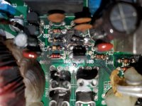
PLEASE PARDON MY TANGENT:drunk:

Folded cascode lateral MOSFET power amp

I am fond of the lateral mosfet OPS power amps and after building two successful examples:
Assemblage Power Amp

and the bigger lin type:

Very HQ power amplifier (Assemblage VII)

I want to build another one with hopefully even better high frequency response.

Recently read this paper by Bob Cordell http://www.cordellaudio.com/JFETs/LSK489appnote.pdf
where I found a DOPA using a folded cascode IPS and decided this would be a good start for my new power amp.

Allready simulated one possibility but have some doubts about it's viability.

My sim indicates this design is stable even without compensation.....
I can not reduce 1khz distortion below 0.015% THD....
I am not sure about the best ccs to use for the folded cascode IPS....

Hope my design captures enough interest and discussion so I can improve this solution.

Please find the schematic and asc file in attach

Best
Ricardo

Attachments

Looking for Alps switch (for Accuphase preamp)

Hi everybody,

I'm desperately looking for a replacement part for an Accuphase C-200V preamp - a tape input/output selector switch, which is no longer available from Accuphase or its authorized distributor in Germany.

It's an Alps rotary switch, 1 pole, 5 positions, 18 tooth serration.

The Alps part no from the current catalog is SRBM150500.

It is impossible (for me) to source this component in Germany, but it might be quite easy in other parts of the world. Maybe someone even has such a switch in his junk box. Please drop me a line if you can help!

Thank you 🙂

Attachments

  • srbm_l.gif
    srbm_l.gif
    6.5 KB · Views: 328

FS pair of GAUSS CETEC 4081 2" compression drivers

This is your chance to own a pair of GAUSS CETEC 4081 2" compression drivers.
These are in nearly new internal condition, the diaphragms are in pristine condition and are phenolic, 4 1/8 inch. 8Ω , 119dB, 300-12000Hz, 17kgr monsters. These are rare as hens teeth and fabulous sounding devices!:redhot:

Yes in the first pic it is the one on the right, the biggest one...24cm in diameter and 15cm height.

Attachments

  • 89567075_10219062286722536_3945440997730680832_n.jpg
    89567075_10219062286722536_3945440997730680832_n.jpg
    31.4 KB · Views: 237
  • 88434821_10219056891027647_3698456760185520128_n.jpg
    88434821_10219056891027647_3698456760185520128_n.jpg
    74.7 KB · Views: 236
  • 89438018_10219056890227627_3500459631128346624_n.jpg
    89438018_10219056890227627_3500459631128346624_n.jpg
    87.9 KB · Views: 239
  • 89394507_10219056891107649_340620202544726016_n.jpg
    89394507_10219056891107649_340620202544726016_n.jpg
    97.2 KB · Views: 218

SpeakerPower Torpedo SP1-4000 Plate Amp Review

Brian Oppegaard, President of SpeakerPower sent me one of his Torpedo SP1-4000 amps for evaluation. Brian spent 11 years as Director of Engineering at QSC Audio Products, Inc. and seven years in the same capacity at Renkus-Heinz before starting Speaker Power in 2002.

SpeakerPower has a wide variety of “plate” amps for use in powered speakers.
The SP-4000 is presently their most powerful amp, and the first amp in which the company makes every circuit board used.

SpeakerPower - Home

The amp is rated 4000W/2 ohm, 2400W/4, 1300W/8, it weighs only 7 lbs.
Front panel has one input, a balanced XLR input with a looping XLR output.
One detented volume control, two push switches, one selects full range response or a 30-80 Hz sub filter, the other a polarity reversal.
A Powercon locking AC input, and a Speakon locking looping speaker output complete the “user interface”. The internal speakers are connected with a latching polarized six pin connector.

The amp itself takes up very little internal volume in a speaker cabinet, and produces almost no heat, critical features for a powered speaker amplifier.

When compared to other amps, the lack of heat produced by the 90-95% efficient SP-4000 was striking. The cool operation also uses less power from the AC power service, very important when using the amp with marginal power. More power delivered to the speakers with less from the wall is not only green, but louder!

So how loud does it go, how does it sound ?

Sounds just like the signal going in, until the clip light goes on. Even after the clip light goes on, very little change in sound quality, the clip light is tied to a very fast limiter. Pushing the amp another 6 dB harder after the clip light illuminates, little harsh clipping sound was generated.
This could actually be a problem for some users who will crank the input until high average power smokes the speakers, since there is very little audible tell tale clipping sound.

The SP-4000 has enough power to cause thermal compression with a pair of Eminence Lab 12 six ohm speakers in a matter of minutes using band limited pink noise run just up to clip. Speaker tests were done with both horn and bass reflex cabinets.
Pink noise has a crest factor of 12 dB, more than some heavy duty compressed dance music, users may exceed the average level of pink noise.
The amp did not heat up even with a nominal 1.5 ohm load, but the speakers sure did!
Without some external limiting to keep average power in check, the SP1-4000 does have enough juice to burn speakers in the 400-700 watt continuous range.

So the amp was able to make the Eminence Lab 12s and a 4015LF sound distressed when hit hard, what about “big gun” speakers?

Just about the time the amp arrived for evaluation I was testing new cabinet designs for the B&C BC18SW115-4, a four ohm 18 inch speaker that handles 1500 watts with around 15 mm Xmax.

I used the SP-4000 for much of the speaker testing, it was nice to not have a noisy fan blowing heat into the shop while the speaker was getting the equivalent power of a space heater.

The BC18SW115-4 speaker could probably take every watt the amp could produce without a strain, so from a “bullet proof” powered speaker application, the amp would be a good choice.
That said, for operators that wish to take advantage of the huge peak potential of the latest crop of super speakers, more power could be used.

Brian is working on an export/high mains voltage version of the SP1-4000 which will do 110 V in to 2 ohms, 6000 watts, using a buck regulator to reduce 180-240 VAC mains to a 190 VDC rail for the amplifier. The SP-4000 has a 170 VDC nominal rail.

Power of the high mains voltage version will be approximately 2000W/8, 4000W/4, 6000W/2. The 2 ohm number is tentative and depends on AC line voltage and quality.

This will also apply to the SP1-2400. At higher mains voltages it will do 2000W/8 4000W/4, but no 2 ohm rating.

Brian is also kicking around the idea of doing a 100-120VAC boost regulator version which will do the same numbers.

He asked me if people will pay the extra $100 or so for the higher power.
I can only answer for myself, if using speakers in the power range of the BC18SW115-4, definitely yes.

Having looked at trends in speakers and amps as they chase each other’s power ratings for almost four decades now, I think the new crop of speakers that can handle 1500 (real) watts and peaks of 3 to 6K will only grow larger, a super power plate amp will be welcome.

Using music and pink noise I tested the SP-4000 against all the amps in house, a Crest CC2800, a Crest CA-9, an old Crown PSA 2 (weighs 8 times more than the SP-4000 !) and a QSC PLX-3602.

All the rack amps are capable of 4 ohm bridged mono operation, so a single four ohm load was used.

With music and pink noise into a BC18SW115-4 loaded bass reflex speaker, the Torpedo equaled the SPL output of the CA-9 and the PLX 3602 (though one 3602 died during testing) put out about 4 dB more than the PSA 2, and 5 dB more than the CC-2800.

Notably, when the SP-4000 was loaded at two ohms, (one speaker and a dummy load) the speaker level only dropped by 1 dB.
None of the other amps could put out as much level as the SP-4000 driving two four ohm loads.
As it stands, the SP-4000 is the highest power commercially available plate amp I know of.

Art Welter

The Leach Amp

I am looking for some opinions....

I recently acquired a commercial Leach amp: The Leach Amp manufactured by LSR&D back in the 80's. It is based on the Leach Low TIM amp design. The specs are fairly impressive, and the power supply is massive. I have had the opportunity to listen to a Leach Double Barrelled amp in a fairly high end system and was impressed with the sound. Listening to this amp for a short period left me disappointed. The sound was veiled and undetailed. The sound stage was almost non existent.

I am driving a pair of Martin Logan Aerius electrostats, but it shouldn't be a problem for the amp. My source is a McCormack CDP and a Curcio Daniel pre amp. My system amp is a Radford ESA225 tube amp (25 wpc Class A) and the basis of my comparison.

So, are the Leach and Radford in two different classes and should I move on in my quest for better sound? Could the Leach be out of spec (it seems to have had a hard life before coming to me!).

Comments and suggestions welcome.

thanks,

Paul

Lenovo Ideapad Z580 Parts/Repair

I have a (non-working) Lenovo Ideapad Z580 15" laptop running Win7. I pulled it out of storage in response to THIS thread. I messed around with it for a couple hours today and seen some sign of life (lights came on), then nothing. It seems a shame to throw it in the trash, but that's where it's going soon. Your's for the cost of shipping. I may advertise it for free locally as well.
Projects by fanatics, for fanatics
Get answers and advice for everyone wanting to learn the art of audio.
Join the Community
507,705
Members
7,885,085
Messages

Filter

Forum Statistics

Threads
406,075
Messages
7,885,085
Members
507,705
Latest member
jeffsguitars