I have been going through a bunch of these line amp/comps lately. A couple for a friend and couple for myself. I really like this unit.
They all needed various mods and refurbed.
I decided to breadboard the preamp only portion to get a better feel fro what is going on. I am not familiar with SS split load Push Pull setup, I am with valve though, so it seemed like a cool tinkering project.
I don't have any of the original AL2712 npn transistors. And I don't have any 2sc2545/s that I see using as a Sub.
I do have a bunch of 2N3392's. And some 2N3053's. So i figured, I'd plop em on a board.
I am using an altec mic to line on the input side and just testing with a shure 57.
I knew I would have trouble getting specs for the output transformer. Or at least I'm under the impression that they are hard to find. So I figured I want an output transformer for low z primary and 600ohm secondary???
I have an edcor XS-1100 here at the house so, I figured I'd try that.
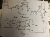
I do realize that the tertiary NFB won't be there, so I just ran a cap in series with the collector load of one of the 2N3053's. With a stock value of 27K feeding the emitter like in the schematic. I realize that this may not reflect the actual NFB being applied by the Stock OT, but it's in place and is working.
I only built the preamp portion of this circuit, the sidechain/LDR circuit is not present.
Basically with a 12VCC supply everything looks good crossed with the schematic, with respect to DC voltages.
OK, here is the problem.
I have the edcor XS-1100 set up, and I think it's terminated properly for the load which it's feeding. An audio converter going in to a +4 line input on the unit.
I'm not getting near the level I would get with mic plugged into the ACTUAL ALTEC units. So something ain't right?????
I will start AC analysis, I did put a 1v 1K sine wave in the front end and found I had a good buffer plus a little gain after (Q1,Q2,Q3).
Coming out of Q5 I had a reduced AC voltage. 1/5th or so. That can't be right. With the NFB lifted it was closer to input voltage. I may have something wrong here.
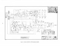
Schematic attached and my hack-reduced schematic for review.
Thanks,
joe
They all needed various mods and refurbed.
I decided to breadboard the preamp only portion to get a better feel fro what is going on. I am not familiar with SS split load Push Pull setup, I am with valve though, so it seemed like a cool tinkering project.
I don't have any of the original AL2712 npn transistors. And I don't have any 2sc2545/s that I see using as a Sub.
I do have a bunch of 2N3392's. And some 2N3053's. So i figured, I'd plop em on a board.
I am using an altec mic to line on the input side and just testing with a shure 57.
I knew I would have trouble getting specs for the output transformer. Or at least I'm under the impression that they are hard to find. So I figured I want an output transformer for low z primary and 600ohm secondary???
I have an edcor XS-1100 here at the house so, I figured I'd try that.
I do realize that the tertiary NFB won't be there, so I just ran a cap in series with the collector load of one of the 2N3053's. With a stock value of 27K feeding the emitter like in the schematic. I realize that this may not reflect the actual NFB being applied by the Stock OT, but it's in place and is working.
I only built the preamp portion of this circuit, the sidechain/LDR circuit is not present.
Basically with a 12VCC supply everything looks good crossed with the schematic, with respect to DC voltages.
OK, here is the problem.
I have the edcor XS-1100 set up, and I think it's terminated properly for the load which it's feeding. An audio converter going in to a +4 line input on the unit.
I'm not getting near the level I would get with mic plugged into the ACTUAL ALTEC units. So something ain't right?????
I will start AC analysis, I did put a 1v 1K sine wave in the front end and found I had a good buffer plus a little gain after (Q1,Q2,Q3).
Coming out of Q5 I had a reduced AC voltage. 1/5th or so. That can't be right. With the NFB lifted it was closer to input voltage. I may have something wrong here.
Schematic attached and my hack-reduced schematic for review.
Thanks,
joe