State of Audiophile world in our Era, and how things changed

Here is the english translation of my (french) thread found here.

I started few threads on DIYaudio in the past years about the blind tests I conducted, such as that one and that's basically my overall conclusions. As simple and straightforward as I could express them. It might even be considered blunt by some... So be it.

In any ways, let's discuss 😉


-------------


It had been a long time since I had plunged back into the design, fabrication and adjustment of sound systems. I've been doing it since the age of 14 and I don't remember having stopped that long since. But, frankly, the last blind tests I made disgusted me a little.

Disgusted by the truth, that our ears and our brain make us hallucinate differences when there is nothing identifiable, therefore nothing real, therefore nothing that justifies investing hours and hours in certain parts of our hobby (or this job, for some). In addition to the tons of money that some pieces of equipment can cost.
But this is not a reason to throw the baby out with the bathwater, just focus on the important and avoid wasting time and money on what makes little or no difference. ..
Here, then, from the experience of around thirty years and after several long and tedious blind tests, my summary of the situation in 2020, in our modern era. As science and technology progress, we will discover other things, but for now that's it:


  • The difference in sound quality between formats: vinyls, CDs, digital MP3 and AAC files as well as streaming does not exist.

    Yes of course, you can have a file or streaming that is too compressed and the poor quality will be easily identifiable, but in 2020 the overwhelming majority will be delivered with a level of quality that exceeds what the human ear could detect as a difference to the uncompressed master file from the studio.
    For vinyl, it's an urban legend propelled by a surge of nostalgia, quite simply. This cake tastes better because mom made it, kind of thing. The audible differences sometimes heard (and very real) are due to a difference in mastering, so not the same source at all, but when comparing oranges with oranges, there is no audible difference. An easy test is to take a turntable and digitize the playback of a vinyl record, then compare both in a blind test of the ABX type.
    The human ear simply does not have the capacity to detect differences, however technically real on paper. We often talk about hearing skills limits, on different aspects, such as: 0.4-0.6db on the amplitude, 1/6 to 1/3 octave on the frequencies, and where an MP3 file as compressed as 160kbps can manage to go unnoticed in a comparison to its high-definition uncompressed counterpart. As an ''audio tool'' the ear-brain combo is unprecise, unreliable and downright weak. No doubt about it anymore.


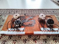
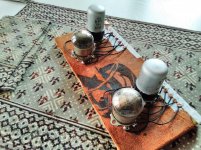
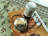
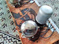
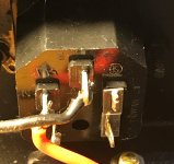
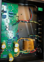
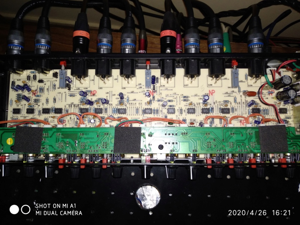
  • Cables, amplifiers, pre-amplifiers, digital / analog converters, all of this has virtually no impact on sound quality.

    Either it works, or it doesn't... or the difference is in the simplest specifications, such as power and level of distortion (amplifiers, etc.). Everything else is esotericism. Nothing is audible to humans, in these esoteric differences. Bottomline, just follow the basic prerequisites for XYZ project, in terms of specifications, electrical requirements and common sense, then everything will be OK.


  • Fortunately or unfortunately, even the speakers do not escape this decapitation of fabulations.

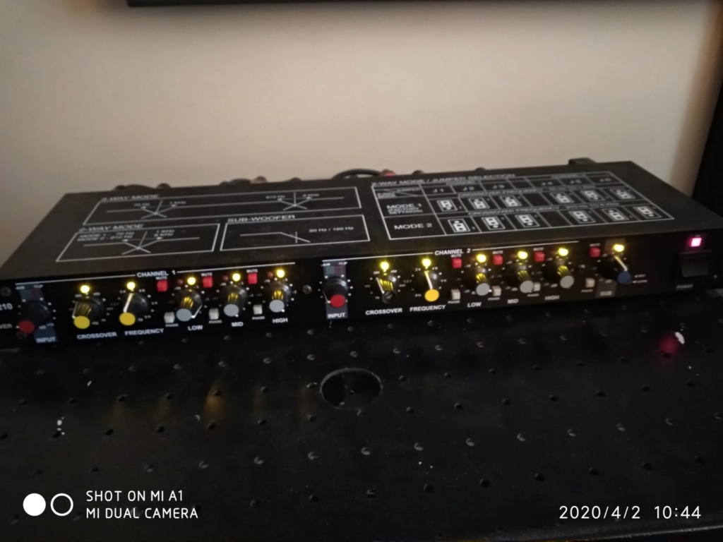
    A ''driver'', this component of loudspeakers, it produces frequencies between (x)Hz and (x)Hz at a certain amplitude (decibel) with a certain capacity of acoustical energy diffusion according to the axis (power response), that's about it. Generally speaking, the quality of sound for the human ear is obtained by achieving a linear frequency range which faithfully covers what we hear, 20Hz to 20,000Hz, for young ears and a little less for older ones. Nowadays the tools exist (DSP) to correct and achieve precise results, and it does not cost very much, especially compared to the so-called ''Hi-Fi'' high-end products... The rest is to find recipes for drivers that work well together: very linear frequency range (flat curve) + maximum extensions at the bottom and the top of the spectrum + amplitude capacity (power, decibels) which avoids to fall into their zones of distortions and mechanical limits. My most recent blind test made a very clear demonstration that a 5$ driver can ''beat'' a 2000$ driver when EQ-corrected and SPL-adjusted, within the same bandwith for both. In other words: a DSP can work magic and save you a lot of money.


  • The Achilles heel of the audiophile domain is now the measures and the capacities/aptitudes of acting on those measures.

    The vast majority of audiophiles, even old timers (especially old timers?) do not know how to measure and make adjustments on a DSP, and/or do not have the proper tools to do so. It takes expertise and experience, which is not given to everyone. So, I think that explains the popularity of sound system solutions that ''self-adjust/calibrate'' with built-in microphones, etc ... I have never heard of such a commercial solution that is really satisfying, but I'm sure it will come someday. It should also be noted that the tooling is also part of the Achilles heel. Indeed, what our ear hears is not the same as our neighbor's pair of ears, and it is very likely that it is far from what the measurement microphone itself picks up. In short, the absolute reference is difficult to obtain and perhaps even downright impossible. The quest for a reliable measurement kit and an correction procedure that satisfies his ears is therefore the key for the modern audiophile and DIY enthusiast.
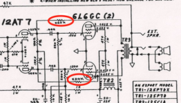
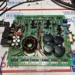
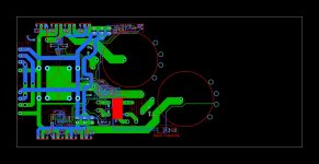
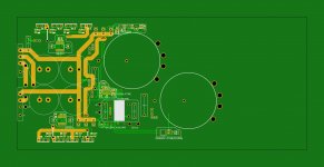
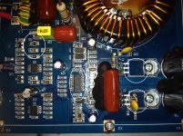
Adding capacitance to SMPS

Hi, I’m aware of the fact that this topic has been already treated many times on this forum, but I wart to ask this question again. Is it worth to add capacitance to a symmetric SMPS? A member of this community some time ago told me that caps, for example, may partly solve the rail pumping problem of class d amps feeded by SMPS. Anyway, how should caps be connected to the power supply considering the two rails?
Many thanks in advance,
Gaetano.

Choosing power supplies for my L25d 8 channel amp.

Hi guys.

I am currently building a fully active three way plus stereo sub system. This is my first real DIY audio adventure and quite a large undertaking – but I am learning a lot and loving it as a new hobby (it’s winter and rolling around under my car isn’t as much fun in the rain and cold!).

I have a MiniDSP 2x8 which will be acting as the pre-amp/crossover/EQ/time-alignment in the audio chain. I have also just ordered a Dayton EMM-6 calibrated mic to use with a newly purchased E-Mu 0404 USB sound card for measurement of room/speakers etc.

The speakers will have the following drivers:

Tweeters: SB Acoustics SB29RDNC-C000-4 [4 ohm neo ring radiator]
Mids: SB Acoustics SB15NRXC30-4 [4 ohm 5”]
Woofers: SB Acoustics SB29NRX75-6 [6 ohm 10”]
Subs: Peerless XLS [8 ohm 10” with 10” 400g passive radiators]

To power these I will need 8 channels of amplification. I originally started looking at HifimeDIY amps about a year ago because of the price and ease of use. I wanted to just plug a meanwell into them and get going. Now I have been lurking enough and reading up on matters I am braver and more proficient with a soldering iron I decided that I would like a kit so I can hand on heart say to people: I made this!

To this end I ordered 4 stereo pairs of ljm_ljm’s L25d. Why the L25d? Because I have only read good things about their sound quality, noise floor, distortion etc etc. Also because they can provide the sub-woofers power handling of 250w into 8 ohm when given high voltage, but have the current capability to drive my 4/6 ohm woofers when used with lower supply voltages. This makes the finished boards more flexible in the long run. It also means (hopefully) that I will be able to scale the power by selecting the power supply for each driver. Obviously the amps are capable of WAY over-powering the drivers but I think that a little self control with the volume knob and lots of extra head-room in terms of power can only be a good thing! I know I have ordered a LOT of power for the mids and tweeters but hope I can scale back by selecting lower voltage supplies and reduce the heat/distortion that comes from the high voltage supplies.

So: onto my question: Can you please help me choose power supplies for my amps? I am basically decided on Connexelectronics regulated SMPS line, but need to choose which exact ones are most suitable for my application.

I am thinking about an SMPS 800R at 70 volts for the sub-woofer amps, an SMPS 500R (voltage undecided) for the [6 ohm 200 watt handling] woofers and a shared SMPS 500 R (voltage un-decided) to power the boards for the tweeters and mids. Later on I could upgrade by buying an SMPS 300R for the tweeter amps maybe?

Can you please talk me through the descision process and choose the right power supplies?

Many thanks for taking the time to read this and I look forward to everyone’s input.

Kind regards,

Jai Stanley

Help for beginner with L25D amp

hi there,

i am new to this forum.
at the moment i am looking for a four channel or two stereo amp to power my active speakers.


so i came across the L15-L25D boards. Since i am an absolute beginner in this area i asked along (ebay shop) if he could also finish/assemble the whole amp. and he would do.
He made me an offer with following parts:

power supply:

http://cgi.ebay.com/ws/eBayISAPI.dll...e=STRK:MESE:IT

trafo-
http://cgi.ebay.com/ws/eBayISAPI.dll...e=STRK:MESE:IT

boards-

http://www.ebay.com/itm/Assembled-L2...item19ce8749dc


before deciding to buy i just want to make sure if these parts are a good combination.- as i really have no idea...

also important is that the amp should be capable of driving at least 3 ohm (imp. min. of the woofer) .


thanks a lot
stefan

Anybody can give me thoses formula for that crossover ?

Hello

I found an interesting 3 way series crossover circuit, but there is no formula to calculate the values of the parts.

Anybody can give me thoses formula for that crossover for 8 ohm drivers ?

I need the crossover frequencies at 150 hz and 2500 hz

Thank

Bye

Gaetan

Attachments

  • Three-Way 1st-Order Crossovers with Woofer Cascade-1.gif
    Three-Way 1st-Order Crossovers with Woofer Cascade-1.gif
    9.3 KB · Views: 294

Unusual VR tube - SR2B by Cerberus?

Hi all,
Just got a pair of these rather unusual (and supposedly rare) VR tubes.
They're marked "SR2B CERBERUS" ,the later being the manufacturer.
What makes them unusual is the double anode feature (see the footnote 1 in the datasheet attached).
I'd like to put them on work,say as a reference VR in a regulated HV PS but I'm not sure how to wire the anode(s).
Any hints?
TIA!

Attachments

New Markaudio Website

A lot of you have asked me over the last year or so when the Mark audio website will be updated with all of the new drivers that have been introduced over the last 18 months or so. I'm pleased to say that not only have they been added, but that there is an entirely new website with new resources for you to take a look at. Cruise by - Markaudio | The home of Markaudio full range drivers You guys will be some of the first to take a look at it so if you find anything that doesn't work properly, be sure to let me know and I'll pass it on.

Low distortion oscillator?

There was an application note I read once that dealt with measuring the distortion of op amps, possibly it was part of a datasheet. Linear Tech or Burr Brown most likely. Anyone remember it? I can't find it anymore.

My existing tools are fine for frequency sweeps, but none of my function generators will not cut it when trying to determine distortion below 0.01%.

I'm thinking I just need a fixed frequency oscillator circuit for around 1kHz and around 0dB (1 V rms) output. For what I intend to do that would work fine ... but I'm unsure about the best approach.

Advice appreciated.

Op-Amp Recommendations

Hi, reasonably new to solid state & op amps; just wondering if anyone could suggest a good op-amp option(s) for a design I'm working on.


Input: Needs to handle a tube preamp stage, can either be high impedance/large signal (up to 80VAC) or low impedance/smaller signal (2-3VAC)


Power Supply: +/-18.5V @ 150mA


Output: Needs to drive a 2.8kOhm input impedance up to 10VAC


Please let me know if you have any thoughts, schematics or recommended gain stage would be extremely appreciated. Thanks!

Need Special 4PDT Toggle Switch

I'm building a slightly improved dummy load for my second test station.
The design uses a single 4PDT toggle switch to select 4/8/16Ω load operation for two independent audio channels.

Honeywell does make such a switch, but it's $52.
I am wondering if there is another source for a 15A toggle switch with the truth table as shown in the attached graphic for less money?

Attachments

  • Annotation 2020-04-30 171437.png
    Annotation 2020-04-30 171437.png
    45.8 KB · Views: 105

Rockford fosgate power 1000bd

Working on a 1000bd. This one is pretty tough to crack. I’ve replaced the power supply MOSFETS with IRF 3205 with 47 ohm gate resistors and replaced the driver transistors. I get 6.90V at the gates. One bank of fets get hot nearest the rectifiers. Thoughts on what to check next? I even went as far as replacing the 3526N ic still same results

Attachments

  • 73D2AB2D-6FE3-4A4E-B06E-84F05C7087E3.jpg
    73D2AB2D-6FE3-4A4E-B06E-84F05C7087E3.jpg
    1 MB · Views: 96

Wire recommendation for Interconnects

I am putting together a design for a car audio upgrade for my Land Cruiser.

I'll need to build a lot of RCA interconnects for it. I'll probably use Switchcraft or Neutrik ends.

I need a wire for a pair from the head unit to DSP and then build 12 interconnects from the DSP to amps.

I am not looking for Litz/Kimber/Cardas/you name it interconnects here. I'm not that guy. Looking for a small diameter wire that would do well in a car environment. Maybe some kind of Mogami or something. Just a nice quiet easily workable smallish wire that will get the job done. Job One will be not draining my wallet un-necessarily!

12 to 14.4v 250A Adjustable Power Supply

Hi everyone,
I usually do car audio repairs, so this is the first time I write in the "Power Supply" section.
I am building a regulated and voltage adjustable power supply for car audio use (during meetings).
I had thought of using an sg3525 as a pulse generator and a pair of IR2113S as drivers for some high voltage mosfets (FDH44N50).
I took a look at this pattern.


https://320volt.com/wp-content/uplo...25-smps-ir2110-smps-900w-70v-power-supply.png


I thought of adopting some modifications to obtain an output voltage ranging from 12v to 14.4v.
I would like to use 2 large toroidal CORE recovered from the power supply of a car audio amplifier which had a power of 3000 real watts rms (obviously rewinding the primary and secondary).
Do you have anything to suggest? or maybe something wrong with the drawing?


I am already working on a printed circuit to be made by the JLCPCB site.
I'm not done yet, a lot of things are missing, but here I post a preview.

Attachments

  • paths.JPG
    paths.JPG
    341.2 KB · Views: 186
  • top layer.JPG
    top layer.JPG
    305.3 KB · Views: 180
  • bottom layer.JPG
    bottom layer.JPG
    203.8 KB · Views: 175

McIntosh C26 Phono Input Problem - Please Help

I'm having a problem with a McIntosh C26 preamp. All inputs except Phono are working beautifully. They test great on a QA401.

The left phono channel works fine however the right phono input channel has very substantial distortion. I believe I've narrowed the problem to the phono amp. A schematic is attached for the relevant circuit. In this section, the phono signal comes in on the coax connected to points 5 & 6. I tested the voltages according to the schematic and compared to the left channel (which works fine). They all test fine except for the voltage at the Collector of Q6. This voltage is not stable on the right channel (is stable on the left). I connected my oscilloscope to that point (i.e. collector of Q6) and get the waveform that's attached as a picture. It appears to be about 20V. Overlaid on the waveform shown in the picture is another regular (mostly sawtooth) wave of about 480kHz. The same test point on the left channel does not exhibit this waveform - just stable DC. I get this problem with any input connected or with the inputs shorted. If the input is not connected I DO NOT get the problem.

I would sure appreciate any thoughts or suggestions.

Attachments

WG500 Waveguide

Dear forumers,

Does anyone even build something as a line array with a WG500 waveguide like PRV Audio has in their program?

B&C has a model that is a couple of inches smaller, model WG400.

I am obtaining to build a two way passive 8 inch cabinet style combined with this PRV Audio WG500 waveguide with 1,4 inch exit.

I was just wondering if somebody use them already.

I will post my build soon with pictures.

Greeting,

Pascal

Passive summing with volume control.

Hey all, i am new to forum. I am trying yo build a passive box to sum 4 mono 3,5mm jack into 1 3,5mm jack . It all has potentiometer on each. Now;
Signal flowing on ch-1, but when i change other “empty” / “no signal flowing” channel’s pot the flowing channel’s level changes. Every channel has 2k resistor on middle leg of pot. Potentiometer’s are 10k value.
I know i will loose some signal. But need to figure that other resistor affecting system.
What to do?

Technics SP-15 Erratic Brake Behavior

Hello,

I am working on this Technics SP-15 from hell. It is trowing problems at me for a while now and the last one is again a special one.

After stop turning during a disc change a couple weeks ago, I have found a donor SL-1300MK2 and I had to replace both DN860 and AN640. Luckily the donor SL-1300MK2 had working parts.

Now that I've got it back spinning again, I see that it does not stop properly. Once I hit Start/Stop button with any of the speeds selected, it slows down but starts turning backwards and forwards a couple times before it comes to a complete halt. I should mention that, I have already performed all the necessary adjustments (the voltages, the current, the tracking) according to the service manual. The Brake pot seems to be fine.

As this very turntable was built in hell, the service manual does not include this problem in the trouble shooting section. Trying to outsmart the sadistic Technics engineers, I have downloaded the service manuals of other direct drive turntables i.e. SL-1200, SL-1300, etc and none of them mention such a behavior as if it shouldn't have happened.

I was wondering if anybody here has/had a tough luck like mine?

Best,
Dirk

Pathos Classic One MKIII

Hello Guys recently I've acquired used Pathos Classic one MKIII amplifier and I'm very happy with it. However I'm little worried about the age of the amplifier as this model is produced back into 2007. I've opened the bottom case to inspect it visually but I'm not any expert on this staff. What worries me a brownish greasy material around some soldering but i don't know if i should use some kind of chemicals like deoxit to clean it. I would be very grateful if some one can take a look at the pictures i took and tell me if i need to visit electrician or to clean it up my self. Here is the link of the images ImageShack - Pathos Classic One MKIII

Thank you very much

3 Way Crossover / Series Parallel Question

Hi, just looking for some confirmation that my understanding is correct.

Say you have a 4 Ohm Woofer, 4 Ohm Mid, and 4 Ohm Tweeter

If creating Linkwitz-Riley crossovers for each component, you would calculate based on them being 4 Ohm.

Does that stay true if I then wire the Mid and Tweeter as series (8 Ohm), and then wire that to the woofer as parallel? Resulting in 2.67 Ohm?

Or, do I need to calculate the crossovers for the mid & tweeter as 8 ohm as they will be part of an 8 Ohm circuit before being tied into the woofer?

Thanks!

Amplifying drivers seperately ?

Hello

I got an idea today about using pc software to separate sound frequencies at a certain point then for testing using left and right channel for each frequencies group with a dual channel IC amp(TDA 7297).
I know I would have to lower the volume of the tweeter compared to the woofer and find the right spot, is there anything I have forgotten or maybe just don't know that I didn't mention ?
Edit: Could the difference in volume amplification be calculated based on the impedance difference of a tweeter and woofer or is it more complicated ?
Also would it cause some kind of distortion if the frequencies cut was a certain number (like 1000Hz so 999Hz goes to woofer but 1000Hz goes to tweeter) or does it need to be done gradually as to lower the volume on the woofer going beyond 1000Hz.

Is it better doing it this way compared to a passive crossover?

Thanks

Suggestion to choose potentiometer for tube preamp

I am finishing assembling the Lite Audio LS26 tube Preamp CAT SL-1 preamplifier and I needed some help in choosing the potentiometer.
At my disposal I have:

Alps Blue 50K
Alps Black Beauty 50K

any suggestions are welcome and consider replacement :scratch2:

At the moment given that I plan to use Alps Black Beauty, is it okay as a value?
Thanks 🙂

Need help about a construction manual

Hello everyone,
I desperately need some help. Does anybody have the copy of "Tele-tech/Electronic Industries" magazine july 1962 issue? I have downloaded this issue from americanradiohistory.com, but the main problem is that there is missing page from 115-118, 116 and 117 no pages are missing. That article is very important for my project and the main 2 pages that describing the circuit diagram are missing. So if anyone in this group luckily have the 1962 july issue of tele-tech/ Electronic Industries without a missing page, please let me know.The name of the article is"design information for regulating and stabilizing HV power supplies" by donald O. Ward.

Thank you all

Cutting my teeth on a refurb project - Klipsch RF-3 II

Greetings!

I am a newb to DIY loudspeakers. I have been lurking in the forums, gathering info, and thinking about what kind of kit I'd like to start with for my first project. I recently picked up an old pair of Klipsch RF-3 II loudspeakers for $150 from craiglist, and the seller also sold me the matching center channel for an additional $40. I saw this as an opporunity to cut my teeth playing with something that could use some restoration and see how much I could improve them! I was actually sort of hoping something would be wrong with them so I could have a real opportunity to make improvements! 🙂

As soon as I got them home, I set them up in my HT system, recalibrated (with Audyssey, on my Integra HT receiver) and then put some music on. The sound was terribly harsh! It was just awful. I like a wide range of music, especially jazz, fusion, classical, and classic rock, and some of it I like to play pretty loud. However, the harshness of these speakers is so bad that I cannot play them as loud as I would sometimes like..

My internet search on the harshness and suggested modifications of Klipsch RF models revealed some facts about the horns on these products; namely, that they are known to sound harsh, and that some people dampen the horns to lower the resonant frequency such as what was done HERE. I also talked with a friend who has some Klipsch RF series in his HT, who informed me that yes, the Klipsch RF lines are in fact known to be harsh, but that they could also be revealing the harshness of my amp. He said he tried damping them with limited success, but also found that using a warmer amp (he suggested B&K or Rotel, and also that they sound particularly good with tubes) really made them sound much better.

But these sounded so bad, there must be something seriously wrong!

I decided I would try to refurbish them to see how good I could get them to sound and then maybe, try a warmer amplifier to see if I can hear a difference. My first attempt would be to damp the speakers similar to what they guy did in the link above. In addition to being able to possibly hear the difference, I always like to SEE the results of my efforts by measuring it. So I did a near field (about 1.5 inches from the baffle) measurment of both tweeters both before and after damping the horn. Boy was I in for a surprise! Both tweeters were almost identical in their response. Here is the result of one of them:
An externally hosted image should be here but it was not working when we last tested it.


I was NOT expecting the huge suck-out at 8kHz! I did however, decide to proceed with damping the horns, just to see what it did. To that end, I found some rope caulk from Home Depot, and I thought I'd try it to see if it both was sticky enough to hold, while being easy enough to remove if I decided to change course. Here is what it looked like, in progress:
An externally hosted image should be here but it was not working when we last tested it.

An externally hosted image should be here but it was not working when we last tested it.


After re-installing the horns, I measured them again and the result was pretty amazing! Here is a screen shot of both a before and after response measurement of one of the tweeters:
An externally hosted image should be here but it was not working when we last tested it.


Please note these are gated measurements using REW without any additional smoothing (as I don't have an anechoic chamber).

So this is encouraging.. The suck-out at 8kHz is gone! However, I see that while the lower range of the response was almost 20db higher than the higher end before damping, it is now almost 10db LOWER at the 3kHz area than it is from about 8-12kHz. This leads me to believe that the material I used is too heavy, providing too much damping? I would appreciate any thoughts or suggestions about this..

My next steps will probably be:
  • Measure the overall response of the loudspeakers to get an idea of how well the crossovers are working
  • Possibly rebuild the crossovers, as designed

I am thinking now that, since these speakers are almost 20 years old, it might be worth while to re-build the crossovers. Please let me know if, from your experience, this might be a worth-while effort. I have some questions about how to approach this that I will address in a new reply to this thread.

Any and all thoughts and suggestions will be much appreciated!

All the best,

Dave

Full range build

Hello, I am currently a student in college and I am building a speaker as part of my project. I want to use a full range driver and I am looking to use Dayton Audio RS100-8 4". I want to make them passive too.

I am extremely knew to this industry and am quite intimidated by it all aha. I know I need other components but I am unsure to what. Could you please help me? Thank you.

Gemtune X1

I am trying to repair a Gemtune X1 amplifier. It had a burnt resistor on the board, I have replaced the blown resistor, but I have noticed there is no wiring coming from the live side of the power connector.

I am looking for a little insight as to where the live wire might connect in the system.

Attachments

  • Gemtune X1 (2).JPG
    Gemtune X1 (2).JPG
    502.3 KB · Views: 235
  • IMG_1790 (2).JPG
    IMG_1790 (2).JPG
    662.3 KB · Views: 228

Car Subs in Home? Box Design?

I guess I should start by saying I think I am over my head.😕 I'm not even sure if what I want to do is possible or worth it. If the answer is no to either just tell me and I'll stop right now.

I have two old subwoofers sitting in my garage doing nothing. I am intrigued by the idea of using them in my home theater system. Am I wrong in assuming that if I buy an amp made for home use that I can use it to power these? If I can, then whats the difference between a regular power amp and a subwoofer amp? The latter seems to be more expensive. But if all I need is the crossover, can't I just use the AVR?

Now for the subs. I know there are differing opinions on these, but I bought them when I was young. I've got two Volfenhag ZX-4712 DVC subs. I'd like to have them in two separate boxes; one on either side of the entertainment center. Possibly tuned differently if I go with ported boxes, or one sealed and one ported. I don't want to get into a complicated design.
Here's all the specs I could find on the subwoofers:
Volfenhag ZX-4712 DVC
4 ohm DVC
500 RMS
20Hz-1.1kHz freq. range
Fs 30Hz
Qts 0.526
Qes 0.614
Qms 7.698
Vas 56L
Xmax 16mm
SPL 89.58 dB
Sd 0.0491
Re 3.2 ohms
mount depth 160mm
mount dia. 282mm

I tried my hand at WinISD but quickly got lost. I entered all the values above but when I went to start a new project it says "Driver data fails integrity check". I added it anyway and started playing around. The EBP (if the values are correct) shows 48.9 which I understand to mean that either a sealed or ported box can be used. If I am looking at this right then the sealed box has a cutoff point at 37.66Hz, which is higher than I was hoping for.

If what I want to do is possible, would anyone be willing to help me figure out the best boxes to build? The outer width and length cannot exceed 20x22. The height can be as high as 28".

Thanks in advance!

Loudspeaker Protection

So let's assume you have a direct coupled amplifier output, (in this case a Tim Mellow OTL) and you are looking to protect your speakers from DC on the output using a relay. Would you use the relay to (a) disconnect the output to the speaker or (b) use the relay to shunt the output to ground (leaving the speaker connected)?

I ask because I'm purchasing a set of PCBs from Ares for my Mellow OTL amp and the the soft start/speaker protection module has a large relay that appears to be in line, so disconnects the loudspeaker if DC appears on the output (I assume above a given small theshold - haven't actually got my hands on the PCBs yet so working from diagrams/pictures). That feels as though it's probably the safest but perhaps not optimal for sound quality and my inclination would be to shunt the output to ground in a fault condition.

Thoughts/comments?

trying to choose between two subs?

I plan to order one today but, I could sure use some input on which one would probably perform the best. I mainly want it for music but, will use once in a while for a movie or two. All help will be appreciated and maybe I can get one ordered today. Thanks! 🙂
Klipsch SPL-150 800 watt 15" Powered Home Theater Subwoofer in Ebony 743878038644 | eBay

SVS PB-2000 Pro Subwoofer | 12-inch Driver | 550 Watts RMS

Recommandations on amplifier to use?

Hi,

-beginner writing here-

I have a set of speakers (see picture), with four KENFORD Typ PA300 8Ohm / 350 W / 96dB

(SPL 96 dB 1 W/m Diameter Voice Coils 63.5 mm, resonant frequency 38.5, Band Width: 48 Hz – 3 K Hz (-3 dB), re, 6.8 ohm, QMS 3.06, Qes 0,5654, Qts 0,4772, VAS 48 L, SD 0,0531 sqm, EBP.)

I'm also connecting two of these COMPRESSION DRIVER TITANIUM 60W
Skytec
Output power 60W
Magnet weight 13 oz
Voice coil 1.3"
Frequency Response 1.600 - 20.000 Hz
SPL @ 1W/1m 105dB
Impedance 8ohm


Could you recommend an amplifier that I could purchase?

My budget is quite on the low side...
Any suggestions welcome!

Many thanks!!
Alex

Attachments

  • IMG_2143.jpg
    IMG_2143.jpg
    976.5 KB · Views: 124

Altec 604's in Sealed Boxes?

I am considering building cabinets for three 604C/D refurbed Altecs I have, and wanted to hear folks thoughts on sealed boxes. I recall that GM has suggested that they might work very well (with woofer/subwoofer support), but I believe his comments were in passing and not elaborated. My application her is a music oriented multichannel/HT room. I know they would be great in big MLTLs, but the smaller cabs will be easier to situate and offer more potential If I need to use them in smaller domestic rooms.

It looks like it might be difficult to go much below 2.5-3.0 cubic feet, so that's the size I'm looking at now. I've been using 605Bs in open baffles with 18" drivers in open back boxes below them for 10 years now, so I'm very comfortable with the duplexes and their crossovers.

This in advance,
Skip

Line transformer or RTX module (RCA to XLR)

I bough a korg nutube b1 preamplifier which has unbalanced output and I'm building an amplifier using icepower 200asc modules, which has a balanced input.

I've seen two ways of converting this unbalanced signal into balanced.

One: use Jensen JT-11P-1 line transformer
Two: use an RTX module (RCA -> XLR)

What are the benefits/which way should I go? My idea is to have both modules inside the same case.

Opening a Marantz CD-48

I've got an elderly Marantz CD-48 CD player that is regularly struggling read a disc or will on occasion reject the disc partway through. I want to start with a good clean-up and hoping someone here can tell me what kind of screw driver I need to get these unusual (to me) screws out.
I suspect a recent development of distortion is also partially down to the player, though I'm pretty certain the caps on my amp need replacing.
Cheers all.

Hair Dryiers, washing machine and a coffee grinder....

Hello !
today i am presenting you quite an interesting "issue".
On the last project i needed very big power transformers, and i have ended up with two big toroids of ~1500VA each.

I was noticing that when i have some house appliances turned on, the transformers began to hum very heavily.

i have connected an hall effect current sensor in series with the primary lead that goes to the wall-socket and i have captured some wafeworms.

oscilloscope is AC-coupled and the sensor outputs 40mv/A

This is when everything is turned of. Transformer is noiseless


this is with the hair dryier turned on on HALF-setting (i think they have used some sort of diode clamping trickeroo to get less heat/less air)

needless to say, in this situation transformers are humming very badly.

quite strange... isn't it ?
the voltage waveform is almost identical in both cases...

Any ideas ?

BrianGT LM3886 Monoblock Inputs

I've recently finished building the wooden chassis for my LM3886 monoblocks from the BrianGT kits, which have been almost 5 years in construction! (For convenience I've been using a lighter-weight Arcam integrated amp as I've moved multiple times since first building these.)


With no load connected, there is a very slight ground hum and almost inaudible hiss, however I believe both of these may be addressed by improved grounding strategy. At present I do not own a suitable pre-amp to drive the monoblocks, so I have been using the output of my Walkman A45 (24bit/96kHz DAC with headphone amplifier) - I understand this must present an impedance matching issue, however I've also noticed that using different 3.5mm to RCA cables can significantly worsen the hum issue - thus I believe the grounding strategy to be the main target. I'm also aware that the port proximity leaves a little to be desired, however I'd prefer to avoid altering the chassis if possible.


My questions are as follows:

  1. As the chassis is insulated, might it be best to remove the AC Earth connection, and if so, where should the CHG (chassis ground) connection on the PCBs be connected to?
  2. Are there differences that could be made in relating the RCA input ground (SG-signal ground) to the amplifier ground rails (PG- or PG+), for example connecting them directly, or any other changes that could be made in the amplifier to counteract the difference in hum between input cables?
  3. As the amplifiers are monoblocks, I wish for them to reside close to the speakers. Is there a best-practice alternative to long (1m) single RCA cables (i.e. shielded, but not in a pair)? It's my understanding that RCAs are kept close to each other to minimise ground loops from http://hifisonix.com/wordpress/wp-content/uploads/2019/02/Ground-Loops.pdf
  4. Do you have any recommendation threads for preamps/buffer circuits to allow hum-free connection to such a handheld player, or laptop DAC source?

Attachments

  • amplifier-in-chassis.JPG
    amplifier-in-chassis.JPG
    745.3 KB · Views: 363

KE-5120 zh. I wish to input via the Din

Hi Guys
I wish to use this old car stereo mainly for its amplifier.
I have seen many "hacks" on you tube soldering directly in to the main board. Not keen.

Reviewing many threads in car audio made me realise the 8 pin Din connector was likely to give a CD player access (I originally presumed it was an output to an external amp).

From another thread's circuit diagram (a GM 120 - thank you) I have considered the pin assignments. i.e. 2 = GRND 3 = R in 4 = L in. See my photo. Correct me if I am wrong.

So, to use these inputs for an AUX connection, I can wire up a 8 pin Din and hey presto! Right?

Hmmm … I don't think its going to be that simple.

I imagine I need to do something with the other pins.

Can anyone comment and point me in the right direction?

Appreciate it

Cheers

Fud

Attachments

  • Pioneer (rear) with pin ID.jpg
    Pioneer (rear) with pin ID.jpg
    962.3 KB · Views: 84
  • Pioneer KE-5120 zh.jpg
    Pioneer KE-5120 zh.jpg
    702.7 KB · Views: 78

Anyone good at promoting lurking about?

Not sure which forum this goes into, it's Music, allright, but there's more people in the Lounge and someone might know something about promoting albums, I am drawing a blank here.

Just put a small collection of tunes up on Bandcamp:
Kaffi 101 | KaffiMann

And then I got a little bit more broke signing up on cdbaby so the stuff gets everywhere (eventually), just waiting for the pencil pushers to get around to it.

If I at least break even, I will consider putting up some more albums/tunes. Not counting on it though.

Does anyone have the ability/skill of getting people excited enough to buy music? I have lot's of other stuff going on with small kids, meetings of various kinds, emails, working overtime etc etc. The list is quite long really.
Is there some reasonably priced ad thing I can do?

And is it enough to pay diyaudio some sum so it might be ok to have a link in my sig? How does this work people? I am clueless!

5687 headphone amp

Hi folks, I want to try with & without opt, only one tube per stereo, attached a couple of schematics & valve data sheet, I will try with & without feeedback, with opt & without opt capacitor. The opt is Edcor USA GXSE5-600-15K 5W 15K-600Ohms. I want advice what of the two schematics sounds better, also I need advice about the new B+ using the 15k-600 ohms opt target of Va is 90V.

TIA
Felipe

Attachments

  • 5687.PDF
    5687.PDF
    52.1 KB · Views: 228
  • 1 tube 5687_lineamp_Thorsten_Loech Esteban mod.gif
    1 tube 5687_lineamp_Thorsten_Loech Esteban mod.gif
    12 KB · Views: 1,620
  • 1 tube 5687_lineamp_Thorsten_Loech.gif
    1 tube 5687_lineamp_Thorsten_Loech.gif
    11.7 KB · Views: 1,590

Good day from Mpumalanga, South Africa

Good day all,

I am a Mechanical Engineer by qualification, a Process Engineering Intern for the Remote Monitoring and Diagnostics Centre for a power utility and hardware/electronics hacker by hobby.

I have always been interested in sound. I used to do sound engineering for my whole school career, played enough instruments to know a bit and even assisted my brother with his car ICE sound offs. I have been limited by budget and experience but now plan to make some good solutions that I'm working and have learned a bit.

I have always loved guitar valvestate amps and had a Sony micro hi-fi with good speakers. I am planning to build a good amp for these 6Ohm Sony SS-H70 speakers. I also have an idea for a low powered system for off-the-grid sound (powered by USB from a battery bank).

I hope this forum can help me fill the gaps and get these projects online.

Keep safe.

Levinson (John Curl) ML-1 Troubleshooting Hum & Other Concerns

A friend loaned me his Levinson ML-1 (John Curl JC-2) that had been sitting in a closet for years.

I plugged it in and noticed a 60 Hz hum but gave it a listen.

Unfortunately, I'm falling in love with this pre-amp but it's freaking ancient! The soundstage & separation of instruments is fantastic😱. I didn't know my speakers were that good.

I studied ME in school, not EE, but I assume the hum is because of an old capacitor? Any help on finding the device(s) causing the hum would be appreciated.

I know the modules are non-serviceable & pricey to replace assuming you can find them - so if a bad module is the problem, I get it.

If anyone has any advice or experience in what I'm facing, I'd be grateful.

Thanks,
Kevin Looker

FS: Firebottle hybrid monoblocks

Having scratched the itch these are up for grabs .
In as new condition and perfect working order.
I will supply several different tubes with them.
The RA power cables are NOT included.
I will be listing my Counterpoint SA-3.1 preamp too once these have sold ,it sounds great with these .

These use pc88 tubes .
65 wpc into 8 ohms.
Input impedance: 60k ohm
Sensitivity: 0.7 volt rms for full output.

£500 + p&p
Please pm if interested

IMG_4230.jpg
IMG_4229.jpg
IMG_4235.jpg

Accuphase schematic

Hello all,

I am looking for a schematic of a Accuphase integrated amp, the E-206.
If the topology of this amp is similar to some of the other accuphase integrateds like E-203 E-202 E-205 and E-207, I'm also interested in those schematics.
I am asked to make an offer on a Accuphase amp which is broken, the seller says the fault is somewhere in the power amp section. He says the output was shorted, but I would think these amp are protected against these faults?
Anyways, what would you guys offer for such an amp? I would like to try and repair it, but with an amp of this complexity this could be a bigger bite than I can chew.

Regards,

Jarno.

Capacitor Reliability

I am re-capping my vintage electronics' electrolytics. This consists of low-level to line-level circuitry operating on +/-18 volt rails. These particular capacitors are NOT in the audio path (I'll use bipolars for that), and used mostly as power supply bypass, ranging in values from 1µF to 1,000µF. I had already planned on sticking to 105c, 5,000 hr capacitors. Would there be any reliability improvement from using 50 volt-rated caps versus 35 volt-rated caps?

Behringer 1400W Class D for B1800D Repair help!!

Hi All.. new to posting but have been lurking for a while reading and trying to learn about Class D amps. I have a Behringer B1800D Sub with integrated 1400W class D.. Amp has failed and am trying to repair it. If any one has schematic.. that would be a lot of help.. but I have looked and looked and cant find any.
Anyway.. buy using what I have learned here and looking at tech reports and data sheets here is what I think it is.

Class D 1400 W..H bridge amp. using self modulation Delta Sigma
Uses IRS20955 gate drivers.. The Fets are IRFB4227;s
I measured +B and -B at about 78 volts. PSU is Behringer SMPSU28
Input and power stage are on Behringer pcb type P0981
I have included some pics of the amp and close ups for reference.

The Amp seemed to fail in steps.. My son said that the Protection light was coming on, but the sub was only putting out about half power. Then it continued to worsen to the point were it would not work at all. Power light would come on.. then Protection would flash and you would here a pop in the speaker, then it would just repeat this cycle. Eventually not even the power light woudl come on.

I unplugged the PSU connections to the P0981 pcb and all voltages seem ok. I did more digging and found both Fets on the B side shorted. Also after doing some resistance measuring and comparing from A side to B side. i determined the 20955 on the B side was toast as well..

Ok, so figured I had it nailed.. I replaced both 20955's with 20957's and replaced all 4 fets just because.

After doing this, I was able to power up the amp. Power light comes on then after a few seconds the Protection LED flashes and that cycle continues. So obviously something still wrong. I assume OC protection. I checked all voltages again at the 20957's everything seems to be where it should be. I watched the V(ds) on the fets with a scope and I see on the A side the High side fet is trying to turn on, voltage is at about 68vdc and drops down to about 30Vdc when the fet turns on for brief moment before the 20957 goes into protection.. On the B side.. I see again the High side fet turning on but the 68 Vcd drops to 0. So.. I think that there is some issue on the A side.. Fet is not turning on all the way or something as it should drop to close to 0 as well. In doing some checking all the sudden the amp stops the reset cycle. I just see the Protection led flash once at poweron.. CSD is charged to 10 V. I found now that VB to VS on the A side is only .8Vdc.. So I probably damaged the chip while trying to check it..and Vbs is not at 15V so chip is not starting up. I swapped the 20957's to confirm the issues moved with the chip. It did.. so I replaced the 20957. Now the amp powers up.. starts to cycle as before. I also noticed the there is just 4.5 vdc on pin 3 ( in) on the A side. and 3.5 on the B side. I measured resistance to gnd on pin 3 and on A side it is about 700K and on B side it is 212k.. so something not right there either.. anyway to make a long story short. i was doing some more testing.. Amp turned on and LIMIT let was on a long time and amp made a weird noise then power shut off and now the A side fets are toast and so is the 20957..UGH..

Sorry for the ramble, but wanted to give you as much info as I could..
Now to the questions.
1) do I have to have some signal at pin 3 ? all i was seeing there was dc voltages.. is this ok ? were does the self oscillation come from would a positive DC voltage here cause the 20957 to try to turn on the H side only thus causing the OC condidtion?

2) I was seeing about 10Vdc offset on VS .. is this normal ?

3) should the High side fet turn on first or the low side.. I read someplace the low side should to charge up Vbs but that seemed to be ok as the chip was turning on and trying to cycle on.

4) I think the OC reset was because the A side fet was not apparently turning on all the way..voltage across is should have been going to 0 i think right?

5) I included a pic of a chip I can't identify.. it is IC6 and has 8 pins It has H04 0'L on it.. I think this is part of the pwm circuit.. i was able to kind trace the singal flow from input to this chip. and I traced from this chip directly to pin 3 on both A and B sides.. I pulled this chip and then when I measure pin 3 to gnd both sides read about 700K ( before B side read 212 ohms) so I think this chip is also toast. I tried powering up the amp with this chip removed and it still did the OC thing and such and then that was when it toasted the A side fets.

Thanks for any input.. I know this is not really a DIY project but if know there are a lot of smart folk on here and thought I could get some advice.and help. I think im close.. but I dont quite understand what I should be seeing at pin 3 with no input signal and what the Fets should be doing at power on..

Attachments

  • IMG_0713.jpg
    IMG_0713.jpg
    653.5 KB · Views: 3,267
  • IMG_0735.JPG
    IMG_0735.JPG
    54.8 KB · Views: 2,838
  • IMG_0739.jpg
    IMG_0739.jpg
    660.2 KB · Views: 2,920
  • IMG_0740.jpg
    IMG_0740.jpg
    943.4 KB · Views: 2,897
  • IMG_0741.jpg
    IMG_0741.jpg
    902.5 KB · Views: 2,543
  • IMG_0744.jpg
    IMG_0744.jpg
    879.2 KB · Views: 1,420

Capacitors issue

Hello.
Bought from Mouser 8 pcs. KEMET 470uF/450v. When opened the pack found two caps are not steady fitted in and have severe rattling inside the shell. I consider this sort of mechanical problem unacceptable and intend to return. But just as information , what can be the cause of this type of fault for a new caps please? The shell have not signs of mechanical shocks to suppose someone dropped to the floor , or some. These are first capacitors I saw rattling and was happened to be fresh new ones. Why ? Thanks.

Attachments

  • 20200428_204136.jpg
    20200428_204136.jpg
    536.3 KB · Views: 166

tpa3116 trouble

Good morning,
I have 2 tpa3116 modules from different sources.
One has a Mute connector provided, but with no connecting info.
Another has a USB reader and no Mute


None will work. Outputs keep silent.
I know the Outputs are not GND connected and kept them well separated from Gnd.


Any idea what is wrong ? Are they so very fragile that they die at a mere glance ?


Pwer: 0-20V
input: from Generator or USB


Thanks a lot for your help !

Newbie amp/monitor build

Hello DIYAudio,

I have a set of Sony speakers (I think they're 150Wx6 Ohm each) from an old micro hi-fi. I wanted to build a Class D receiver/amplifier for them to use in my workshop. But I can't work out how to safely (and frankly cheaply for these cheap speakers) go about doing this.

The actual amplifier and filters etc. wasn't my problem. (I have in-depth "hacker level" experience with building circuits and working with chips etc.). But I a) didn't know if there were better or worse quality Class D Chips and b) couldn't work out what was the safest, most cost effective and best quality to choose between all the transformer stages with the power supply. For example, does an AC or DC power supply result in better sound quality with a TPA Class D chip.

My question is, what is the best way to use these speakers for less than $100? I can't justify spending more on them, but if that's too low please feel free to just tell me that I'm being overly optimistic.

I have no idea what I want the solution to be, I am just asking for a one line response or link from the DIYAudio pro's. It doesn't need to be Class D. It doesn't need to be a standalone receiver/amplifier but I didn't know if a "little" box on the back would be powerful enough. Giving them Bluetooth capabilities would be a great bonus, but yet again I just want to know if I can still use these speakers or should just bin them.

Thank for your advice!View attachment Sony SS-H701.pdf

New build: Mullard 5-10

Hi

Newbie to this forum and looking forward to participating. Also hoping this is the place to get some advice about the feasibility of constructing a vintage amp?

Just for fun I'd like to have a go at building a 1954 Mullard design for a 5 valve 10 watt high quality amp (I believe affectionately known as the Mullard 5-10).

I have a copy of Mullard's construction booklet and there is also a quite detailed article on the amp on The National Valve Museum website (Mullard 5-10. Ten Watt Amplifier)

I have chosen this particular amp because I happen to have the booklet, but I have read on wikipedia (Mullard 5-10 - Wikipedia) that the circuit design was famous for its unique sound reproduction, so it will be interesting to find out.

The valves are no problem (EF86, ECC83, EL84 and GZ30), but I am concerned about the two transformers (mains and output). I doubt I will be able to get hold of original NOS ones so can someone help by advising me of a suitable modern alternative for each?

I have attached the relevant section of the booklet which refers to the transformers, the choice of which I understand depends upon loading. Three arrangements of the output stage are possible: normal loading, low loading and distributed loading. For want of any specific knowledge I guess it would be sensible to opt for normal loading.

Hope someone can help.

Attachments

  • Mullard 5-10 transformers.jpg
    Mullard 5-10 transformers.jpg
    249.6 KB · Views: 1,634

Impedance curve to spice equivalent in LTSpice

I have a thought of frequency dependent load ( this is how a speaker with enclosure behaves.) simulation . This will help me to built cross over and see how this behaves. not only that but we will also help me generate wave file which I can run on actual speakers and measure performance and hear how likely would this final design would perform. this will highly eliminate the need of buying crossover components for every small change.

So I am looking for how do I incorporate frequency dependent load with LTspice if have impedance measurement file in csv format.

Thanks.

Which capacitor is dying in Heathkit AR-15 power amp circuit?

Hi all. I have this Heathkit AR-15 here, and it has had this symptom: One channel takes a good fifteen seconds to come fully alive. It moves from zero sound through distorted sound to full-on sound. But then at intervals it gets distorted again.
I think it has finally decided to die, though, because it will not come fully up out of distortion-land anymore.
It has this massive output capacitor, a 4000 mfd giant cylinder. Well, it HAD one; the previous owner (I am a recent Ebay buyer of this much-treasured receiver. At least by me) replaced it with a nice new one, I think Nakamichi? I can look up the brand but I've just put it all back together and don't feel like taking it back apart just now. The point is that it's been replaced so I am inclined to disregard it as the culprit. But I'm in over my head; I'm just an amateur; I do not know how to determine which component (because I'm not sure it's a capacitor, except that this problem tends to be due to a dying capacitor, from what I've heard).
I know it's advisable to do a complete re-cap, or at least it is for some people. For the moment, though, I'd like to isolate the culprit, replace it, and get back to listening.
I'm posting the schematic for the power amplifier section. I ran a test to make sure the problem is in the power amp (took the pre-amp output and ran it through another amplifier. It sounds OK).
Could somebody take a look at the circuit and tell me, in their opinion, which capacitor (assuming it is a capacitor) would be the one you'd suspect of having died?
Or what else could the problem be?
I'd really appreciate anybody further along in this hobby than me - I'm just a dilettante.

I've circled the electrolytics in the circuit on the schematic.

Thanks for any help.

Bob H.

Attachments

What's Going On?

I use Verizon Fios - the lowest tier (migation from DSL in 2017) service, and just as cheap.
But now, for some reason I've got blazing fast speeds!
(I did several "online speed tests" to confirm this)

I didn't upgrade anything, nor will I pay for something I didn't order.
Anybody got any ideas?

Attachments

  • speed test 4-29-2020.jpg
    speed test 4-29-2020.jpg
    55.5 KB · Views: 176

manually/externally paralleling amplifier channels, and bridged-parallel operation

This topic has been brought up before in various versions, but here we go again...

So I have a bunch of 2-channel amplifier modules that I harvested from a Crestron CNAMPX-16x60. These are class AB 60W into 8R, 90W into 4R. In the amp there are 8, 2-ch modules for a total of 16 channels run from two large toroidal transformers. With the amp disassembled I am planning to use these in active speaker projects.

In one potential speaker system, I would like to use a 4 Ohm subwoofer but 90W is a little on the lean side in terms of the power requirement. So I am dreaming of using a pair of the 2-channel modules to create a bridged-parallel connection to the sub.

Just to get it out of the way, I understand about load sharing, gain mismatch, and DC offset issues. I will try to trim gain and match DC offset between channels, and was envisioning using series resistance on the order of 0.22R on the output of each channel. I will drive each pair of (+) and (-) channels using an audio interface with the (-) channels inverted.

This seems relatively straightforward, as long as some caution is used, however, I would be reassured by some practical and gentle positive feedback from the great minds of the forum. What sez ye? TIA.

Help a tube amp guy orient himself on an F5 build

Hi All,


I need more amp for some new speakers (100W, 91db/2.82V) and I'm thinking of foregoing my typical affinity for tube amps to try something different. I'd like to hit 100W at 4 ohms just to be sure I have maximum headroom for peaks but this is negotiable. The F5 is a nice easy build that gets me 40W at 4 ohms but I'm worried I will regret not maxing out my headroom. A turbo V1 gets me to my the target wattage but has more unknowns for me to deal with. So, I'm a bit torn between the ease of building a standard F5 and the potential complications of building an F5T (note that turbo boards are out of stock as of this post). I've read through the F5 and F5T docs several times and burned though hundreds of pages of posts and it's all sloshing around in my head so please help me get a few things clear:

  • The F5 doc specs distortion at 40W into 4 ohms as .2% but does it clip there or is there a little more power albeit at a slightly higher distortion level?
  • Can the 4U deluxe chassis from the store handle the dissipation of F5T V1 if I ever want to reuse or modify?
  • Can the Linear Systems jfets in the store handle the higher rail voltages of the turbo without cascoding or is that reserved for Toshiba parts only (with some established risk)?
  • Early in the turbo document, after suggesting the higher rail voltages in a standard F5 circuit, Mr. Pass says, "Want to drive 4 ohms with this? You can do it, but I recommend that you consider the upgrade to the F5 Turbo V1". I'm wondering what are the consequences of running 4 ohms at higher voltages - particularly if you are not pushing the volume most of the time.
  • Would parallel output devices or reduced source resistors increase power into 4 ohms at all? I'm thinking not, but would like confirmation.

So, what you can probably ascertain from my questions is whether or not I can build a standard F5 today and keep a relatively short path to a turbo later, or if I can do something between a standard and turbo V1 now. For example, I could see myself hacking in a second set of output devices later without swapping out the boards, but adding cascodes not so much. Swapping out the transformer and filtering would be costly but easy, a new chassis not so much.


Sorry for the lengthy post but I've already spent several days running in circles and I find myself unable to pull the trigger on parts.


Brian
Projects by fanatics, for fanatics
Get answers and advice for everyone wanting to learn the art of audio.
Join the Community
507,706
Members
7,885,146
Messages

Filter

Forum Statistics

Threads
406,079
Messages
7,885,146
Members
507,706
Latest member
thatchacha10