Pioneer Ke-4444 revival

This thread is going to be about the KE-4444 I bought in case the KE-1818 was dead. Unfortunately when I plugged the KE-4444 into my car, it did not turn on.

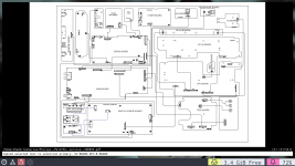
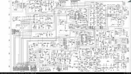
Without a wiring diagram, diagnosing it is going to be rather difficult. It is exhibiting the same symptoms as the KE-1818 did. No lights, no display, no nothing. I am hoping that it at least shares the same microcontroller as the KE-1818.

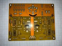
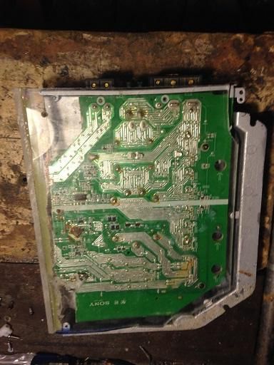
First step is going to be taking it apart and checking the silk screen to ensure pioneer didnt pull some sort of shenanigans and change the wiring between the two. If thats not the case, check for power at the switch. If thats good, check the microcontroller for power and signal (if its the same as the other unit).

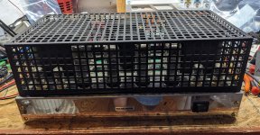
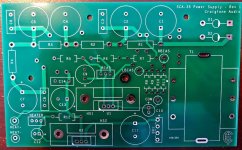
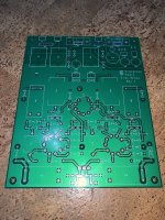
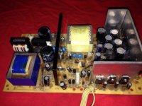
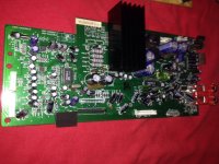
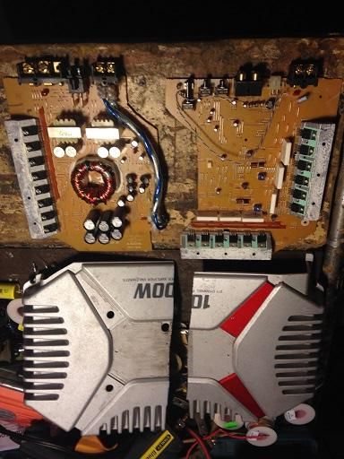
If I cannot figure out the issue from there, I will need some help. I will do my best to take pictures of the boards. The KE-4444 has more boards in it (riser cards / daughter boards?) than the KE-1818 did.

FS: JDS Labs O2 Headphone Amp (like new) - NO BATTERIES

I bought this O2 brand new from JDS directly. I took some measurements and posted my review. After that, the amp sat on a shelf collecting dust. That's a crying shame, so since I no longer need it, I figured I'd sell it.

I took the amp out of storage and tested it. It works as good as new. The batteries would no longer hold a charge, so I removed them. Thus, the amp you will receive will NOT have any batteries installed. They were 9V NiMH types. The amp runs just fine from the wall wart and I'm sure you can find replacement batteries locally should you need battery operation.

The amp comes with the original wall wart, original box, and original self-adhesive rubber feet (that I never installed).

I'm thinking $80 including tracked Canada Post shipping within North America. Bump it up to $90 if you want it shipped by UPS. The amp is $140+shipping new from JDS. (SOLD)
I'm happy to ship it overseas as well. Contact me directly for a shipping quote to overseas locations.

I check email multiple times per day, so that tends to be the best way to reach me. Take my user ID here and add @neurochrome.com. I do check my PM somewhat regularly, though, so that's an option as well.

Tom

Attachments

  • O2-Front.jpg
    O2-Front.jpg
    260.6 KB · Views: 291
  • O2-Rear.jpg
    O2-Rear.jpg
    249.3 KB · Views: 295
  • O2-Full.jpg
    O2-Full.jpg
    243.4 KB · Views: 291

graaf gm20 shorting resistor

HI , hope somebody can help me with my dilemma.

The resistor number R02 on the power supply section shorted,

I am planning to replace it ,but am afraid it would escalate to another problem, this all started when i replaced the trimpot for the dc offset of the left channel, since the trim pot was not able to trim the voltage.
I did this is to try to fix my actual or initial problem ,which was no signal outptut on the left channel.

Hope someone out there could give me a heads up on what to lookout for before i replace the resistor.

Attachments

Techeunion TU-9015 or Unistar 15A2

attachment.php


This looks identical to the Unistar 15A2, and the PCB is marked as such.

I'm posting this mostly as a way to have a little more information out there about this amp. And I have a question about it. But if not, hopefully this will help someone someday with one.

A coworker got this amplifier from her father and asked me about it. Nearly nothing can be found about Techeunion on the internet(other than not cheap anyway), but found a statement(later decided was false) that made me really curious about it and I could see solid state inside too. So I offered to check it out and recap it cheap so I could look it over. Decided to make a schematic for it. Lots of notes in the schematic. Interesting design with the plates at chassis voltage. SS soft start. Diodes to protect the grids from being positive to cathodes on startup, see above about the plate voltages. No capacitors in the pre stage.

The amp was supposedly bought new in Taiwan in the mid to late 1980s. What little I find online is that the tubes are 12AT7×2, 12AU×2, EL34(6CA7)×4. Someone wiped the markings off the tubes, except for the first tube which is a 12AX7. Someone also J-hooked a 76K resistor inline with the factory 100K feeding the input tubes. The amp has enough gain that a preamp isn't really needed. Was hoping someone would come along here and tell me what tube is supposed to be where. My gut feeling is 12AT7 in the input stage, and 12AU7 in the phase spliter stage. And someone, again supposedly never worked on, add the resistance to rebias the input tubes.

Amp is quite heavy, so I expect it's got good iron. Build quality is quite high. Sounds very good to my ears with my speakers. If I can keep the amplifier a while I might try to do some actual measurements on it. I give it a 'would like it in my room' rating. Board is decapped in pictures.

Thanks
Cory

Attachments

  • unistar15A2.pdf
    unistar15A2.pdf
    163.6 KB · Views: 340
  • IMG_20200628_163757.jpg
    IMG_20200628_163757.jpg
    993.9 KB · Views: 436
  • IMG_20200628_163726.jpg
    IMG_20200628_163726.jpg
    1 MB · Views: 134

Turning Tesla Model X into a (Removeable) folded horn.

First off, why do this? I miss GREATLY my JBL 18" KX 151 twin loaded sugar scoops. They turned into handtrucks (great to toss gear and records into for rolling into Gigs, but now 39 years later I have a 57 year old spine.

I miss Dj'ing as I always made the ladies scream those Beatle mania type screams at the women's colleges around Boston.

Then last year at a HS reunion I Dj'ed out of my Model X and again great reactions.

I can't carry gear anymore

It occurred to me that the sloping roofline of Tesla Model X might work as a subwoofer in a folded horn application.


Skip this next section....as its just FUN detail:

------------------

I have (2) MC4000M 1000 watt amplifiers (used for all the systems below) . Which at one time I used one of those to run a Roller Disco at an outdoor roller rink that had no power. each is 4 x 100 and 2 x 300 watts into 4 ohms but have no issue running 2 or even 1 ohm loads.

The Tesla has a huge battery.

I have access to lots of production master tapes and the car does triple duty thanks to some front end swappable modules.

1. Introducing people to the audiophile world. EAR 912 pre amp, Otari 5050b reel to reel with mastertape, and Wadia 860x DAC , Speakers are Chapman T-8

2. Analog DJ rig with Technics 1200 GAE, Bozak DLC mixer ,Chapman T-8 and Genelec S30d as monitors for small parties.

3. Digital DJ rig Technics DZ-1200MK2 and Vestax VCI-100

But I realize I need some REAL bass reinforcement and frankly hearing people perform with QSC and JBL EON just makes me think people are lazy and tone deaf.

SO my thought is my old favorite AlNiCo KX 151 18" drivers in a folded horn using the car as the horn , some sort of array of 12"midbass drivers compression midrange and super tweeter.

I have 6 band 4 channel Mcintosh Parametric EQ, and a 5 way 4 channel Electronic crossover with 4 memory settings to easily convert.

---------------

So could anyone suggest how I could make a baffle that press fits into the car with these drivers?

Am I just a foolish idiot? Rhetorical question... but I hope there is another brilliant idiot out there that can see my vision.

Drop me a PM and I an happy send you videos of what has been done already.

This will also be used for Aspen Race department and for ESPN Winter X games.

reciever pream/power amp seperation

working on a vintage luxman r1040 , I'm getting what seems to be dirty pot noise , have cleaned as well as I know how with very good cleaner and still get an intermittent large dose of R channel static .
Question : is there a practical way to isolate the power amp section of this piece ? Also , if someone wants to recommend a repair for the existing problem please do.


thanks

'Engineered by Audio Note' EVGA's Nu Audio sound card

Asus Xonar (and, to some extent, Creative) PC soundcards seem to have held their ground despite lack of upgrades to their lines.

Now it's EVGA's turn. At $250.00, the card seems to offer quite a package (see links).

Darko wrote:
EVGA -- among audio circles they barely rate a mention but for those building PCs the Californian motherboards and graphics card manufacturer is much bigger news. For their latest product, EVGA teamed up with Audio Note UK for a most unlikely collaboration.

The NU Audio Card sports a multi-layer PCB with passive heatsinking and 'isolated dual ground planes', presumably to hold back (the negative influence of) electrical noise from infiltrating both analogue and digital sections. Audio Note UK's in-house developed capacitors and resistors feature in the card's fully-regulated power supply and analogue circuitry.

On D/A conversion, we see a pair of oscillators (one each for 44.1kHz and 48kHz families) clock an XMOS chip's output into an AKM AK4493 decoder chip (PCM up to 32bit/384kHz and DSD256) which in turn feeds the card's analogue output stage: an ADI AD8056 op-amp spills via a pair of RCA sockets and is fully rollable.

Rollable too is the ADI OPA275 dual op-amp that forms the backbone of the 6.4mm (variable) headphone output that offers an output impedance <1 Ohm. It's reportedly good for headphones whose rated between 16 Ohms and 600 Ohms.

On volume control, we are not necessarily forced into the digital domain (where DSD doesn't play). EVGA's own software interfaces with the NU Audio Card's Maxim DS1882 controller for fully analogue attenuation and, making hi-fi purists wince,'audio reactive' lighting.

A TOSLINK output is there, ready and waiting, for when we upgrade to a superior sounding outboard DAC.

For signals moving in the other direction --for those who like to do needledrops of their favourite records -- the NU Audio Card also features an AKM AK5572-powered ADC, fed via a 3.5mm socket. For gamers, the all-important mic-in socket rounds out the EVGA card's feature set.

And whilst EVGA is almost certainly aiming this audiophile-grade sound card at gamers and PC builders, hi-fi enthusiasts might wonder if high-end audio server/streamer manufacturers will see the NU Audio Card as a drop-in solution for their own products. Time will tell.

EVGA - Articles - EVGA Nu Audio
'Engineered by Audio Note': EVGA's Nu Audio sound card | Darko.Audio

evga-anuk-board.png


An externally hosted image should be here but it was not working when we last tested it.

Fostex P1000-BH frequency response. Really only 270 Hz?

Hi,

I have the these cabinets with the FE103En drivers. I originally bought them because I was intrigued with the back-horn concept. I now have my bigger back-horn towers, so no more 'novelty' on these. I use them as my computer speakers powered by a Rotel RA-12.

Fostex rates the tuning frequency as 270 Hz. which is crazy-high. Is this 'real' or in the real world would these be outputting lower bass?

I am thinking about 'downgrading' to the ported box as they are tuned to 80 Hz. - question is, should I expect to actually get more and power bass?

My drivers: Fostex FE103En 4" Full Range

My current cabinets: Enclosure: P1000-BH - Back-loaded Horn Enclosure Box for P1000K | Speaker Components| Fostex

What I am thinking of getting instead: Fostex P1000E DIY Kanspea 4" Full Range Speaker Kit - PAIR: Madisound Speaker Components

Thanks!

Ken

BIAS setting problem on amplifier

Hi everyone !

I have designed the attached schematic in NI multisim. Everything works brilliant on the simulation software.
I have done a test pcb as well and built the amplifier. After some errors repaired (reversed cap, reversed diode - was my mistake) I have managed to have the amp playing music.

Anyway, something is wrong on the BIAS adjust section. I can't adjust the BIAS from the trimmer although in the simulation it works perfectly.

With no load connected to the output, when powering up I get around 50mA current for 20-40 sec and after that the current goes to 0.35Amp constant.
With the load connected to the output, it draws 0.35Amp.

Can you please help ?

Kind regards,
Julian

Attachments

  • Katherine_100AS.png
    Katherine_100AS.png
    76.2 KB · Views: 256

Woofer or subwoofer?

My kit consists of repurposed boxes containing full range drivers and a Seas tweeter with first order capacitor @ 6.8uf

Have space for a pair of 6.5” woofers or subwoofers wired in the box is 14”tall x8” wide 11” deep

Seems to be lacking in low end

I do use a POS Polk 10” sub but would dearly love to sack it

any helpful contributions would be valued and appreciated

please no criticism of the setup, love it and just wish to address a 6.5” driver a possible elements to achieve desired outcome

Thank!

New Project - Network Streaming Device (Pi4/Hifiberry)

Gz5AXjx.jpg


* Raspberry Pi 4 (2gb)
* Hifiberry DAC+ DSP
* micro SD card for the OS
* Volumio Audiophile Music Player (Debian based Linux distribution customized for the pi and music streaming)

The hardware build only took about 20 mins: Imgur: The magic of the Internet

* Connected to my NAD integrated amp via optical cable.
* Connected to my home network via wifi. I'm going to change this to a hard wired ethernet connection after I free up an additional port.

The software took a bit longer... Days longer. Ran into some issues.

But first, what went right:https://imgur.com/a/usRswBB

  • Installing the OS and getting the basic player and streaming functions was not that difficult. Volumio found all my network shares & Plex server easily. Access to the box via my phone's browser was also pretty simple. Pretty much all functions can be controlled remotely that way, or by using a web browser on a laptop, desktop or tablet (windows & mac).
  • Spotify connect was enabled easily enough through an available plugin for Volumio.
  • Volumio has native tidal and Qobuz support for the paid license.
  • There's always airplay and bluetooth connectivity built in for when you have no other more direct streaming options.

Now, onto what went wrong:

Installing the software to access the 'DSP' part of the Hifiberry board proved to be quite a challenge!

  • The DSP Tools software package that interfaces with the DSP chipset requires a recent version of Python. Volumio is built on an older version which the DSP Tools doesn't support. So a Python 3.x version needed to be compiled and installed.
  • The instructions to do this, while lengthy, did not look too daunting. I'm no stranger to the Linux command line, though not an expert by any stretch of the imagination.
  • This also means getting 2 versions of Python to play nice together on the same machine in such a way that the applications that require the older version can find it, as well as other applications/packages requiring Python 3.x to be able to find it. This is where I ran into trouble, Errors upon errors returned after following instructions to the letter. I ended up reformatting the SD card and starting from scratch 3 times to get this right. In the end, I have not yet been able to get DSPtools installed correctly in order to access the DSP functions.
  • I have had some wonderful help from a user over on the Volumio forums that has a similar hardware setup. I'll post updates.

lwgTr8e.png

Can we talk about series/pass regulators?

I've been doing some reading on series tube regulators lately.

References:

http://www.audioxpress.com/assets/upload/files/bicknell2890.pdf

Tube Based Voltage Regulators - Part 1

http://www.diyaudio.com/forums/tubes-valves/90020-perfect-tube-regulator.html#post1059442

Also Radio Amateur's Handbook and other odds and ends I have on my bookshelf.

I'm interesting in trying something around a 12AX7 and 6AQ5/6BQ5 or similar. I'd like to use it to power a small SET (6V6 or 6BQ5 output, probably) with one regulator per channel. I also have a couple 6CK4s and 6Y6GAs that look like they'd be useful as pass tubes.

What I'm having trouble finding is information on the maximum permissible current through the series tube. Is it as simple as dividing the maximum dissipation by the voltage drop across the series tube? For something like a 6BQ5 with a 150V drop, that gives 80mA, but this seems very high and I don't see any designs operating at or advertising this much current with this tube or similar. Or should I use the maximum permissible cathode current (65mA in the case of EL84 according to some data sheets)? The latter makes more sense, but it's still very high if compared to many of the designs I've seen.

It seems that lower currents allow for better regulation. Is this a function of the series tube Rp as it relates to the voltage drop divided by the current passed (in that we want the Rp to be much lower than this figure, like when calculating for load impedance in an output)? In that context I think I see why there would be practical current limits to provide useful regulation. That might also mean that a higher gain error amplifier would allow regulation for higher currents (within the limitations of the max cathode current). Not sure if thinking about this like a load calculation is correct though.

Can anyone point me to some more reading or shed light on how to spec series regulator tubes?

GE Tungar Battery eliminator / Charger

I have recently restored a Tungar Bulb Charger. It is working great. This model was used not only to charge car batteries but was used as a Tube Radio battery eliminator. I have the 2A model. It has multiple taps.

Tungar Battery-Charger for A and B Power-S General Electric

My question is, if I use this as a battery eliminator what kind of filter would I need to create? Given that it has a high current output does that mean I can use modern high value filter caps?

If I use it as a Battery Charger would I still need to filter it if I intend to add a charger cutoff circuit to protect the battery?. I know many chargers use pulsing DC, but will the circuit linked below have an issue with that?

12v Automatic Charger (Auto Cut OFF) : 3 Steps (with Pictures) - Instructables

I don't really have a plan for what I intend to build, but I do intend to use it one way or another.

The charge cut off schematic uses 1N4007 diodes, could they be replaced with tubes? The Transistor?

I could also use it to supply field coil voltage as in this thread:

Tungar Power Supply

Would I still need a Power Transformer given that the unit already has a power transformer built in? Looks like the circuit in the thread used just the bulbs. I have read the charger can still be unsafe as is.

I'm looking for advice and suggestions on how I could make this restored charger useful for some project in the future.

FS: JBL 2226J (quantity 2) 15" woofers

Long story short, had these things for years, unused, sitting wrapped up in my closet. When I got them, one of the cones was damaged and was re-coned my JBL in Northridge (the application of the epoxy looks different than the other).

Asking $300 for the pair (buyer pays shipping), or a reasonable offer. If you are in Minneapolis then obviously it is fate!

If you have questions let me know!

Thanks,

Ken

threshold T200

Hi, I have a T200 threshold and I am updating it with all the new trainers.
I have checked all the components and the surprise when I turn it on is that in the right channel at the exit the DC is 270mv
and in the left channel 8.75volts and do not regulate the bias, always checking it with a lamp in series in AC.
I've checked everything and I don't see anything wrong in a vacuum. They could help me.
Cheers

More on Output Stage Local Feedback

No, it follows the normal triode behavior but it is very small distortion and good enough to get an amplifier that satifies with IEC standards (i.e. <0.2% THD from 20Hz to 20KHz at FULL rated power). Distortion at 1W is 0.01% or less.
Compare the distortions in the UL driver with the driver running on the output stage, with the "single link". Apparently, Mackintosh did not know what kind of work he could offer his engineers in the last 40 years.🙄

FS: Misc Project PCB's

1. BUF03 LDR Preamp - If you have some BUF03's, this is hard to beat! Requires bipolar PS. Includes offset trim for each BUF03, and LED balance trim for LDR mismatch. SOLD

2. EAR phono - This is a deluxe version with OEM PS. This has all the options to emulate the Romy the Cat and Thorsten mods. Multiple B+ cap options (electrolytic, film 2-pin and film 4-pin). Coupling cap sized to accomodate Obbligato Golds. SOLD

3. MM/MC RIAA Opamp - Single op-amp with negative RIAA feedback. Has switch provisions to adjust cart loading and gain for a single MM/MC switch. Pick your favorite op-amp. 8 left. $12 shipped

4. Dynaco SCA-35 Upgrade - Includes PS cap replacements, Adjustable fixed bias circuit and DC heater supply (w/transformer) for phono stage. Fits in cap mounting holes. $25 shipped

5. WAD Phono - EXCELLENT phono stage with built-in Series Pass Regulator and DC heater supplies. This beat the EAR above in neutrality. SOLD

6. Zen Amp - Picked this off eBay and decided not to build. SOLD

7. Vintage Cap Adapters - These are great for updating old amps with chassis mount cans. Bolt these to OEM holes and solder in a Jensen (or equiv. pin space) modern electrolytic. Available in chassis grounded or isolated versions. SOLD

ALL of these have been built and tested (except the Zen). I do have pics of finished working boards if anyone wants to see them. I will provide all info needed to build these as required.

Attachments

  • BUF03.jpg
    BUF03.jpg
    99.5 KB · Views: 427
  • EAR.JPG
    EAR.JPG
    353.2 KB · Views: 433
  • RIAA.jpg
    RIAA.jpg
    159.4 KB · Views: 430
  • SCA-35.jpg
    SCA-35.jpg
    129.8 KB · Views: 421
  • WAD.JPG
    WAD.JPG
    308.3 KB · Views: 414
  • ZEN.jpg
    ZEN.jpg
    153 KB · Views: 156
  • CapAdapt.JPG
    CapAdapt.JPG
    250.6 KB · Views: 178

FS: Lots of high end op amps (AD797, AD8620 etc)

Note: If interested, post in this thread or PM me. Do not email.

As I have no apparent use for some of the of op amps in my stock anymore, they gots to go.
Every sensitive component in my little lab is always handled properly, with ESD protection and no fingerprints on stuff. Here we go:

Stereo AD797BRZ, DIP-compatible: Two AD797B (SOIC package) soldered on each side of a small gold immersion PCB, with gold plated mill-max pins.
These are of the best grade (B) I think these are overkill for audio, but hey, sometimes you need overkill. €30 each
Links: Datasheet | Analog Devices | Mouser

AD797ANZ. Single op amp in DIP package. €10 each
Links: Datasheet | Analog Devices | Mouser

AD8620ARZ. Dual op amp in SOIC package. Made DIP-compatible with gold immersion PCB and gold plated mill-max pins. €15 each.
Links: Analog Devices | Datasheet | Mouser

AD8610ARZ. Single version of the AD8620, in SOIC package, with some improved specs over the dual version here above. (see datasheet)
Made DIP-compatible with gold immersion PCB and gold plated mill-max pins. €8 each.
Links: Analog Devices | Datasheet | Mouser

AD845KNZ. Still my favorite preamp op amp. Single, in DIP package. €15 each.
Links: Analog Devices | Datasheet | Mouser

The solder work of the adapters are of professional quality, cleaned after soldering of course.
The ultra sonic cleaner broke a while ago but I got a new one coming, and will clean the (already clean) parts once again before shipment.
I tried to take some photos but I soon found out its very hard to take nice ones on small things like this. But if you really need it, I'll just have to try again I guess.

Shipping from Sweden. I will not send these out untracked. Tracking worldwide is aprox 11 euros.
Let me know if there's anything weird about the prices.
In Sweden, we pay 25% tax on everything we import. This is reflected on the prices. (I paid aprox €40 in material for the stereo ad797b)


I don't know if I really have to state the obvious, but I do it anyways: These parts are not bought from eBay or such, which adds the risk of fake items significantly nowadays. These comes from reputable sources such as Mouser and Digi-Key.

(UK) Supravox 165-2000, 285GMF, Radian 475Pb

(UK) Supravox 165-2000, 285GMF, Radian 475Pb, MiniDSP

For sale in the Uk:
To fund the Tannoys, I have the following DIY speaker bits for sale:

1x Pair Supravox 165-2000 (mk1) full range drivers - **£700**
Bought new in 2018, originally out of spec so returned to Supravox to be re-manufactured, now a very well matched pair.


Supravox 165-2000 by Robert Seymour, on Flickr

1x Pair Supravox 285GMF mid bass drivers - **£350**
Bought new in 2019, very low use.


Supravox 285GMF by Robert Seymour, on Flickr

1x Pair Radian 475PB (16 Ohms) - **£200**
Bought second hand in 2019,very little use.


Radian 475PB by Robert Seymour, on Flickr

1x Pair Faital Pro LTH102 Horns - **£50**
Bought new 2019, installed once and then boxed.


FaitalPro LTH102 by Robert Seymour, on Flickr

1x MiniDSP 2x4HD - £180
Used, comes with remote/power cable/original packaging.


MiniDSP 2x4HD by Robert Seymour, on Flickr

Karlsonator for Prosound 8" L74AW and planar tweeters

Hello everyone, got a pair of these prosound drivers for like 6e the pair and thought I'd slam them in a karlsonator with some planar tweeters sitting on top (no k tube as the shape of the tweet is rectangular). I cannot find proper TS parameters (hence this design, more flex with those poorly documented drivers). Now my problem is obvious. Which size of box should i go for? Anyone can find the tsp? And all kind of help appreciated.

Thank you team

puddletag - new developments

Hi.

puddletag IMO used to be the best audio tagging software under Linux.
I found it equally good as mp3tag under Windows.

Since a couple of years it's no longer maintained though. Unfortunately this happens all the time with very promising projects in Linux land.

The application ran stable for years. That was the case until beginning of this year.

The issue.

Starting 2020 Python 2.x will no longer be maintained. And. puddletag is based on Python 2.x.

A port to Python 3.x was needed. The designer was no longer in the boat. A community
effort was required.

The great news. A port project is full at swing.

I've been testing the git version under Fedora and Wayland. Most of the functions work fine by now.

The big issue I see is a public release of the new fork.

A lot of work for an application goes into the coding. However. Huge efforts also go into (online-) documentation, distribution, maintenance, communications.

I'm not sure yet how this is going to progress. Perhaps it'll remain one of thousands
github-only projects.

Keep the fingers crossed that the team manages to go public at one point in time.

For the hackers and advanced users out there it'll be possible to install the fork manually from git sources of course.

Enjoy.

2sa607/2sc960 to-39 subs for JVC vn900 amp board

Hello all. I have recapped my vn900 about 2 years ago. And I was looking to replace some of the transistors on the amp boards. But I couldn’t find a good replacement for 2sc960/2sa607. So much just left it alone until now while playing relay started clicking on and off until it just never came back on, after further examination I discovered the two transistors went bad. So here I am trying to find a good replacement for them. Also I have read a lot abou a good replacement for the stv-3 bias diode. Does any one have a definite answer to a good replacement for it Is really unclear to me weather you can make one your self. Does any body have any experience making one ??
Your input is greatly appreciated

Creating a transformer saturation device

Hi,
I am experimenting and wish to create an audio saturation device to run my instruments through and get that transformer saturation sound.

I got 2 of these transformers 119DA rated at 12w.
Hammond Mfg. - "Classic" 600 Ohm - Speaker Matching Transformer - Hammond P/N 119DA

And got this:
Permalloy Audio Signal Transformer 600Ω: 30K, 7 times boost boost signal, frequency response 23Hz ~ 36KHz -3DB

Buy Products Online from China Wholesalers at Aliexpress.com

And i have a 2 channel 140w amp outputs 8 or 4 Ohms, that i can use to power the transformers.
My end goal would be to saturate the transformers and step it down to live level to record it.

I ran a 50Hz sine wave input to the amp, and hooked up the secondary 8 Ohms of the 119DA transformers to the hi-level out of the amp. The signal is amplified from 25v max to 60v max. (I measure the ACV with a multimeter)

I haven't hooked up the other 600:30k pair yet but i can't seem to saturate the transformer, the sine wave somes out clean.

Any ideas on what to do to achieve saturation?

Thanks,
Mike

Pass Pearl 2 troubleshooting help needed, low output in one channel.

Hi Gang,

A friend was kind enough to give me a pair of populated boards, and it was gesture I greatly appreciated as I have been swooning over them for years. He made one "small" mistake which I thought was on purpose.. he left out the LED's completely. That made R29 smoke in both channels.

So, I replaced R29 on both boards and installed LEDs with the correct polarity. I brought the boards up and one of them still smoked R29. I found a short in Q11 and replaced it. This channel works properly.

The other channel didn't obviously cook any transistors. I just dropped in a fresh 100 ohm resistor at R29 and tested it out. This channel shows a dramatically lower output. The only oddity I can find is higher voltage at the Collector of Q11. I can't seem to figure out why.

I am going to be totally upfront and say I am a total rookie at this type of thing and usually can't successfully diagnose a circuit because I don't truly understand how it all works. I also can't count out an assembly error of some sort by my friend.

Any help is appreciated, I am dying to hear this thing!! I borrowed my friends and really liked it a lot.

Thanks in advance.

HiFiBerry AMP2 Power Issue

Recently took delivery of one of these amps, which I connected to my working RPi 3B loaded with MoOde. I initially connected it using a 19.2V PSU, one that I've successfully used to power my Zoudio amp previously.

No +5V. The board says 18V at the input terminals. So I tried a 16V PSU. Get +5V this time, but not for long.

The only way it runs with the 16V PSU is if I co-power it using the ordinary pi 5V input. It plays correctly. If I remove the additional 5V PSU, it drops out within a few seconds.

Do I have a defective AMP2 module?

HiFiBerry says it's supposed to power the pi and then some from the amplifier power input. I know the TAS amps are good for 24V and HiFiBerry only warns against using >18V with 4 ohm speakers... Implying it should work with , oh, 19.3V input and 8 Ohm speakers which I have.

I'm using the screw terminals, versus the quick connect for the PSU connection.

Any help would be appreciated. Thanks!

555 Timer DC Protect / Turn-On Delay

I have been working on a simple design for a turn on delay and DC protection utilizing the venerable NE555 timer and have encountered and interesting issue.

I decided to prototype the design quickly on some perfboard following simulation success. I only had a ratty old salvaged 555 chip that I wasn't even sure was OK, so I stopped at the local junk monger to pick up a few new ones. So, I cobble up the test circuit (see attached) with the recommended local decoupling and such and of course it didn't work as was expected (otherwise I wouldn't be asking 😉).

Well initially I can say my issue was self induced as I inadvertently applied a supply voltage that was too high and may have ruined one. After realizing my error I re-configured my PSU for a proper supply voltage and installed a new 555. Still wasn't working. Removed the second new 555 and double checked everything again, no errors found. I decided to pop in the ancient old 555 and here is where it gets interesting - the circuit worked exactly as expected.

OK, no apparent error. One possibly toasted 555 was my fault, another seemed to be DOA. Curiosity got me as I had bought four and had only tried two new ones thus far. I decided to try the others and found they did not work as expected either, but whenever the old one was inserted, voila, it would work.

Now to my question. Does anyone KNOW what, if anything, would cause three new 555s to not function (I actually found another unused one that did not appear to work either, so four in total) while the really old one worked perfectly? They are all bipolar devices, no CMOS ones were used. Is there some fundamental difference between the construction of the old vs new that is the difference? I thought the 555 was basically unchanged since 1970 so expected them to all behave the same. Am I wrong?

Attachments

  • NE555 Protect.png
    NE555 Protect.png
    41.2 KB · Views: 2,176

Overseas shipping delay time

The coronavirus situation obviously had an impact on delivery time of the goods (in our case diy parts). I'm still waiting for items to arrive after two months (item was send from USA).
I have a hesitation every time I find something and the shop is overseas

What your experience with orders you've made lately ? Also did you have an experience where you've finally received an order after months of waiting ?
Does Mouser/Digikey/big shops have the same week or so delivery period ?

Crossover LCR meter measurement

I bought an LCR meter to measure the values of unmarked crossover components. I now realise that the meter measures impedances and calculates values for LCR. The issue is that the values displayed depend on the frequency setting. However when I buy an inductor/resistor/capacitor, they aren't specified as having a particular value at a particular frequency. So how do I know which measurement to use to obtain the actual value of the component in crossover? Thanks.

FS Dayton Audio Esoteric ES140Ti-8 midbass drive units

Up for sale I have a pair of Dayton Audio ES140Ti-8 5 1/2in midbass drivers from their Esoteric series. Drivers are brand-new-in-box.

The 140 has a superb spec.; key features include a woven fibreglass cone of large central cap design. Finite element designed motor with neodymium ring-magnet, dual copper shorting rings, 3in edge-wound CCAW voice-coil with titanium former, long-throw suspension, tethered tinsel leads. Klippel optimised suspension. Heavily vented motor and extremely open cast basket design. I've attached some Dayton images as it's an impressive looking unit.

As noted above, brand-new-in box. Asking for £80 for the pair + shipping, which is about £60 less than some European sellers are asking for a single unit.

On the subject of packaging, they are in their original Dayton Audio boxes. I use sustainable FSC rated outer cardboard boxes fastened with heavy-duty packing tape. These are reinforced inside with recycled heavy-duty cardboard and packed with recycled brown / grey packing paper and high quality bubble-insulation.

As always, thanks for looking. 🙂

Attachments

  • eso1.jpg
    eso1.jpg
    103 KB · Views: 462
  • es02.jpg
    es02.jpg
    56.4 KB · Views: 470
  • es03.jpg
    es03.jpg
    66.6 KB · Views: 460

Large lot of transistors,diodes, LEDs, etc

Thousands of pieces, hundreds of different part #s, too many part #s to document and list here. Most are (>90%) NOS, I imagine from 10-30 yrs old but some may be newer. More parts then are shown in the photos, I think they can be stuffed into a 22x17x16 box weighing 35lbs. My zip is 17036 and prefer to ship via FedEx, so you should be able to get a shipping estimate at FedEx based on the above information. I will not ship international, it will cost more then the parts!


Price is $99 for the entire lot, prefer local pickup.

Attachments

  • IMGP5160.jpg
    IMGP5160.jpg
    783.6 KB · Views: 208
  • IMGP5164.jpg
    IMGP5164.jpg
    688.5 KB · Views: 206
  • IMGP5165.jpg
    IMGP5165.jpg
    674.9 KB · Views: 199
  • IMGP5166.jpg
    IMGP5166.jpg
    929.1 KB · Views: 242

Krell KSA100S jumps into its security

Dear DIY enthusiasts and professionals, My Krell KSA100S jumps into its security immediately after switching on. I have no money to buy such an amplifier again, so a repair is my last rescue. Could any of you help me with a schedule or repair manual? I would be very grateful to you. Thank you in advance for your effort! kind regards Arnold Bergen.

Please critique - Studio Monitor - SEOS 12 + 2x6" Mid-Woofer + 18" Sub

3 way high SPL sealed studio monitor

Edit - Changed the title of the thread to better reflect the current ideas.

Hello,

Apologies, I have started similar threads before, but got confused and waylaid by other projects.

I build music studios. I have built several pairs of custom speakers for my studio builds... mostly derived from proven designs. I have a superficial understanding of some things, but I can be flummoxed easily.

I want to build a sealed, 'limited range' (100 Hz - 20 KHz) monitor which will function well @ 2m-4m listening distances. The accepted studio protocol (per ITU 775) is an equidistant triangle between the speakers and the listener, with L&R angled @ 30 degrees.

In my current demo room, I have Tannoy DC12i (with a coaxial 12" driver) and custom subwoofers with AE TD15H drivers. One of my main problems is that the stereo imaging is much more stable further back into the room from where I'm sitting (the speakers are about 9' apart and I'm sitting @ about 8' - this is 1' ahead of the theoretical "sweet spot"). I'm hoping that a smaller mid-woofer will beam less and widen the sweet spot.

I already have a pair of B&C DE250s in SEOS 12 waveguides. I'd like to use the DE250s for sure (they sound absolutely great to my ear, in a pair of 4 Pi speakers I built), but I'm willing to consider a smaller waveguide if it will help me increase my XO frequency (between mid-woofer and CD), for a wider sweet spot at a closer listening distance...

System will be tri-amped with Class D amplifiers, and managed by MiniDSP 4x10HD, with analysis and tuning help from REW.

At this time, I'm thinking that bass duties will most likely be handled by a JBL 4645c, simply because it is very inexpensive here. Luckily, it will serve as a great stand for the mid-woofer/HF speaker and bring the listening axis point up to the recommended 4' above floor level. I'm also thinking about a Peerless by Tymphany STW-350F in a custom sealed enclosure, but that is for another thread.
Right now I am focussed on the mid-high component.

Goals:

* 82 dB average / 102 dB peaks @ 4m, from ~100 Hz to ~18 KHz (some active Eq may have to be applied to achieve this, of course). (85/105 dB is the film standard - but for smaller rooms, the kind that these speakers are intended for... 82/102 should be sufficient.)

* Suitable for listening distances of 2m-4m.

* Sealed enclosures that can be easily customised to different rooms by varying the dimensions, but keeping the internal volume constant.

At this time, my questions are -

* Will a pair of Eighteen Sound 6ND430s per side do the job? What alternatives should I consider?

* If so, how high can I cross them over to the DE250s in SEOS12 waveguides? Or should I consider keeping the XO point as low as possible, in order to minimise interference problems between the mid-woofers?

* Will a smaller waveguide such as the Eighteen Sound XT120 be preferable for a higher XO point (~2 KHz)

* Are there any fundamental flaws to this approach?

Thanks in advance,

PS: I'm stuck in a total lockdown/quarantine situation. I can't access my PC which is in my studio, in which I have WinISD - the only speaker design software I'm familiar with... Pity there seems to be no similar software for Mac...

Attachments

  • Screenshot 2020-06-23 at 4.26.06 PM.png
    Screenshot 2020-06-23 at 4.26.06 PM.png
    29.5 KB · Views: 495

Diy Subwoofer Amplifier?

I'm interested in building a DIY two channel, stereo, external subwoofer amplifier that can easily power up to two 12" subs at moderate listening levels. 200-300W RMS per channel? Balanced inputs would be nice.

I'll be using mDSP to integrate into my stereo system.

I'm looking for the ability to play around with different passive subwoofers in different enclosures mix and match with different speakers.

I've been looking at HypeX module's, icepower at PE, plus a ton of others and I have absolutely thoroughly confused myself.

I've never built an amplifier before so I would like something on the easier side, my electronic skills are limited to a few computer builds, a couple of sets of crossovers and general around the house/farm electrical work.

If anyone has any suggestions where to start, links to good proven designs, or any advice in general I am all ears.

Budget is around $500 or so, less would be great, more if necessary.

Thanks.

Best CCS for 15mA & output transformer

I have a SE triode headphone amp based 5687 actually with OPT air gaped so no output cap.

I want to use cascode CCS in place of OPT load, I have DN2540, IXTP 01N100D & LND150 so I'm looking for the best suited CCS for my needs: what upper or lower position device, etc.?

Also I need to use the OPT to reduce the output impedance but I have doubts if I need an output capacitor between the CCS & the output gaped transformer, if yes how can calculate the value?

TIA guys.

Restoring the TDA8920TH from Philips Stereo.

Hi,
So I want to restore the amp and PSU that I took out from an old Philips FWD750, I just want the aux functionality but I realized the aux inputs to MUX which send the signal and receives it back from another circuit board to communicate with IR sensors from the remote, I am planning to get the output without sending the signal to the other board just using the PSU and the main board. My initial Idea is to simulate the orginal layout in KiCad and try and get the output signals, however I can't find the Pspice model for TDA8920TH is the simulation neccesary or I can get the output just via inspection and changing or adding some circuit elements?

Attachments

  • 1587469015.png
    1587469015.png
    252.5 KB · Views: 81
  • 1587757272.png
    1587757272.png
    583.8 KB · Views: 82
  • signal-2020-06-27-094308.jpeg
    signal-2020-06-27-094308.jpeg
    261.9 KB · Views: 76
  • signal-2020-06-27-094325.jpeg
    signal-2020-06-27-094325.jpeg
    346.2 KB · Views: 73

Damping 1960s console speakers

I have a pair of 12" Sears Silvertone cabinets that match a 6BQ5 Silvertone stereo receiver. They're nicely made as in they're furniture like and built to last, but they're pretty resonant, especially in the mid-bass. Rap on the cabs and the woofer baskets even give a pretty good ring. I'm planning on replacing the speakers with full range Fanes, but I want to at least get resonance down to kabuki speaker levels.

They're only one cubic foot, so I want very thin and efficient damping. I was thinking Peel and Seal and/or Dynamat stuff. I like the idea of self-adhesive products. And some fiberglass batting on the floor of the cab. Am I barking up the right tree? Are these even tameable? Any way to brace them without woodworking skills?

Attachments

  • 20200526_130115_50.jpg
    20200526_130115_50.jpg
    479.1 KB · Views: 272
  • rsz_20200524_183408.jpg
    rsz_20200524_183408.jpg
    379.2 KB · Views: 264
  • 20200526_130103.jpg
    20200526_130103.jpg
    779.7 KB · Views: 301
  • rsz_20200526_125522_50.jpg
    rsz_20200526_125522_50.jpg
    264.3 KB · Views: 264

2 x 3 way boombox.

Hello all
So I know there are a zillion of topics about it but all being very specific and different from the one i aim to do, I am posting this thread. This time I dont want to go for a cheap option but more mid prices (budget 300 to 500). I have few issues I would need help with, which are as follow:
1 drivers:
I picked them according to qts, frequency range, fs and overall sizes and if i had the choice, design.
- 2 x DS-115-8 Dayton or DA-115 both 4"
- 2 x HiVi b3s midrange 3"
- 2 x Goldwood GT510 1"

2 cabinet
Horizontally stacked design with separate enclosures for bass of 25mm baltic birch plywood or maple
Size: h: 35cms L: 50 W:35
3 radiators

2 x 3" woox radiators

4 amplifier

1 x tda7492 upgrade to 2.1 later with a 4 output amp from Sure. Will bridge 2 channels with a xo to create a subwoofer channel

5 crossovers

Chinese stuff for peanuts according to answers here.

6 power and electronic

1 x dual VU meter
1 x UPS system with 12v witb 7000 mAh
1 x phone dock (optional)
1 x bluetooth receiver with usb and sd card
1 x battery charge meter
1 x odroid board (optional)

The problems/questions i have are:

If i dont align the speakers putting high and low together on each sides and mids in the center, will it have a big impact on the sound quality ?
Do i need to enclose the mids?
Can i enclose the bass into a sealed box with radiatore pushing out into a flat tunnel towards the side leaving the mids and high in the rest of the box in br?or ported?
Will it need bracing?
Is the volume enough?
Fastening using the factory screw holes or a pointy thingy pressing the driver against the bafflee


Thank you all for your help

I got more but it will come as i buid. I am not a full on noob I actually build speakers for over 10 years but passive and i just dumbly followed schematics and never bother with doing the engineering and all i self engineered i got super lucky it sounded decent (when it did... which wasnt too often)
Also, anyone knows a free program to mske a 3d model? Preferably pn Linux

Comparison Of 2 Pole Compensations

Why to use 2 poles instead of one? On the contrary what people think , it has nothing to do with the stability, but the purpose is to widen the open loop bandwidth. Very grand majority of designers don't give any attention to this aspect, after all there are one thousand and one opamps with open loop bandwidth of few hertz and they have the reputation of excellence. So why to bother about open loop bandwidth?
The first aspect is to have a uniform NFB applied to the whole spectrum, same treatment to all 20-20khz without segregation.
The second aspect comes from tube amplifiers. In Williamson for example the OL bandwidth is 10khz limited by the OPT, 20db NFB is applied . With large OL bandwidth , on the transient of the input burst , the phase starts nearly what it will be on steady state . Whereas in very low OL bandwidth , it starts with -90° phase shift to reach gradually to that of steady state. This phenomena , provokes transient distortion if multiple voices burst at same time interval. To hear what I mean ,listen with a low OL the requiem of Verdi YouTube . With my aging ears I can clearly hear enhancement to 30khz OL bandwidth my be a sensation to 40Khz but above I don't think is necessary , but if can why not.
The VAS circuit that will be submitted to all kinds of 2 pole compensation techniques has OL bandwidth of about 4khz, to widen it to at least 20khz.
attachment.php


There are four different types of 2 pole compensation I found . TPC,TMC,Cherry NDFL and dadod's OIPTC. I will try all of them , and evaluate comparatively.
If you have suggestions to try out this or that , please be welcomed .
Hayk

Attachments

  • VAS+CASCODE 2pole.JPG
    VAS+CASCODE 2pole.JPG
    128.1 KB · Views: 1,052

Bias on Aragon Palladium

I have just bought a pair of Aragon Palladium’s- the original version from the early ‘90s

Would just like to give them a small service with an adjustment of the bias current an a change or cleaning of the speaker relays.

I can’t seem to find any info anywhere about the alignment procedure - so I would be very happy if any of you could tip me on where to find the service manual ? 🙂

If I decide to change to caps in the power supply or maybe a full recap - what would be a good brand to buy and would it be safe to go 20-30% up in capacity?

USB sound card's EEPROM reading/(re)flashing

Hi,

I have a simple SA9023 USB-to-Optical/Coax converter.
The story below is not too important though, I would need general understanding first

While trying to use the converter with Raspberry Pi I faced several USB related unstable "miracles", the converter perfectly/stably works with PC though. I suspect the converter EEPROM content is not consistent enough (there are some null string descriptors in there at least).
Maybe there is a chance to fix that, but looks like I just don't understand some basics to move forward. Would be happy if somebody could navigate me a bit.

So some general subjects I would like to understand, rather general than the device related.
Unfortunately I'm newbie with that.

1 A USB device has a chip (SA9023 in my case) and (SPI/I2C) EEPROM. Is there a way to access (read/write) the eeprom via USB. Or it could be only possible via a standalone programmer with a clip connected directly to the eeprom?
I know that some USB devices allow the underlying eeprom programming via USB registers. Sometimes it's briefly documented, but usually not.
Actually almost any USB device has a chip + eeprom, so the eeprom content (initial at least) population should be performed anyhow and it should be technological enough (for manufactures). It's hard to imagine a "man with a clip" in a factory.
Maybe there is just a common approach I'm not aware of. Or it's a vendor/device dependent "zoo"? The datasheets are typically silent at this point.

2 A modern USB device typically has a chip + eeprom. So there is a reason to believe the eeprom stores not data only but code for internal processor as well. It's hard to believe the chips are not universal enough as there is a lot of various devices based on the same chip.
However the datasheets include nothing about the processor, its type, commands set, internal registers, peripheral addressing, ports etc. Could it be it's just too common and well-known? So no information is available unconditionally and I'm just not aware of.
Anyway such firmwares were developed anyhow and (most probably) developed independently from the processor core, So the information should exists somewhere,
Could it be there is just a kind of "8051" processor inside and everybody know that excepting me? It's hard to believe every USB device manufacture creates its own processor to produce the device. Is there something to start reading from?

Thank you in advance

Wood combination for 3 way speaker

I have designed 3way home Hifi speakers
- inner net volume 150l
- 12'' woofer
- BR tuned to 22 Hz
- MTM
- 3 braces vertically (tolal height 1200mm)
- SPL 1W 1m 94db, RPM input power 120W
I would like to make the design similar to CANTON 1.2 DC but with only one woofer.

My idea is:
1. milling solid wood for front baffle 45/25mm hard wood
2a. 22mm MDF otherwise
2b or 20mm MDF + 2.5mm HDF (with some veneer)

It combination of solid wood with MDF (or MDF+HDF) good Idea or
make it completelly from solid hard wood?

Thanks for any suggestions.
Peter.

Alpair internal cabinet reflections

What frequency range tends to be most affected by internal cabinet reflections in a shallow enclosure for the Alpair metal line?

I am hoping cross over at 4th order HP @ 300Hz on an Alpair 5.2 and I am wondering if I am avoiding some of the trouble area or if the frequencies into the lower mid-range and above are most affected?

I am aiming for 5" internal depth in a wall-mount cabinet. There will be an LDW7 in the same cabinet but it will be in an isolated compartment.

DIY Cheap Car Amp: SMPS from broken amp + TDA7294 Chip amp boards

Several years ago I picked up a used broken Sony Xplod amp Model XM-2185 GTX rated 165W x 2 into 4 ohms. Poking the volt meter around I discovered that the SMPS was still pumping out around +- 38 volts DC. But could not figure out what else was wrong with it. So I tossed it to the side for another day.

Flash forward to another day and I have a co worker who wants a cheap car audio upgrade for his newer Nissan Versa keeping the stock head unit. Well let's see what I have laying around the house: How about what I picked up a while back at one of Part's Express buyout/closeouts: 4 ohm Peerless SDS woofer Peerless 835004 SDS 6-1/2" Woofer 4 Ohm | 299-250 for like $10 each. Plus some tweets and a leftover crossover (I have active in my car) and I have half the problem solved.

As for amplification. Well, what can I do with the old Sony amp with working power supply? First, I got lucky and found the service manual: Sony XM2165GTX Service Manual free download,schematics,datasheets,eeprom bins,pcb,repair info for test equipment and electronics It's using a TL594 as SMPS controller feeding 6 power MOSFETS (FKV550N) 3 each leg. Specs on the MOSFETs say 50v/50A. Also from the look at the PC board and the circuit diagram, I could cut the board in half and have just the SMPS with a single row of the MOSFETs plus the two double diode rectifiers all sharing the one side of the heat sink/case. So I decided to cut the board and the metal case to provide heat sinking as well as protection. I also wired the +- DC output to what were the normal speaker outputs for one of the no longer used two channels. I'll post pictures of this abomination later. Yes, its pretty fugly. Edit: As promised, don't laugh:

ExplodedAmpInTwo_zps940f4735.jpg

(Above: Pic of split Xplode amp with SMPS power coming out front previously speaker terminals.)

ExplodeSMPSBack_zpsa3b2c831.jpg

(Above: Bottom view of SMPS with homemade plexiglass cover.)

ExplodSMPSFront_zpsa4f061a5.jpg

(Above view of SMPS portion of XPlode amp) Soon to painted flat black and hidden.

Now I have power, what can I do with it and on the cheap? How about a chip amp? A little ebaying brought up a pair of TDA7294 boards assembled from China for like <$17 including shipping. Can't beat that!
TDA7294Boards_zpsb7ccafd5.jpg


So I've been wondering about heat sinking the chip amps and mounting the resulting mess in this guy's car. The solution I've come up with is building a shelf under the rear deck (in the trunk) to hang down at most 3 to 4 inches to hide the ugly SMPS amp and the chip amps. As for cooling, I have a big old CPU heat sink from a Dell that was being tossed at the office. Looks like:
BigDellHeatsink_zpsdeb625dd.jpg


I probably could put both chip amps on it, but I'm going to pick up another heat sink just like it (from ebay). So my plan is to have the old SMPS power supply on one side of the shelf and on the other have two of these heat sinks on their side with a 80mm (or so) case fan blowing thru the two of them. I also have a couple extra surplus big 'ole electrolytic caps like 30,000uF @ 50v to shore up the wimpy 3 x 2200uF per leg caps on the original SMPS board. Of course, mounted externally to the SMPS since they are kind of big.

My thinking is on most car amps the SMPS and all channels being amplified are all on the same heat sink/chassis. Splitting the SMPS from the amplification would reduce size (two smaller thingies are easier to hide/install than one big one). And the split would run cooler since the heat is spread and separated. Putting the chip amps apart from each other would also help.

I'll probably share this project with the guys over at DIY Mobile audio as well. I have a spreadsheet with the totals I have spent on this project which includes new 8 gauge power wire, fuse, ring terminals, 3 sheets of RAAMmat deadener. Total so far is under $150.

Hello from U.K.

Hi .. :wave:I’m a Mechanical Engineer by trade ,:yikes: but interested in the DARK ART of electronics ..😕
I Currently have a valve audio system consisting of Audio Innovations - second Audio monoblocks , with Boarder patrol PSU’s fed from Series 1000 pre amp and Series 1000 SUT from my custom built turntable that is based on Lenco mechanics, and fed from a variable PSU that I built , albeit from a BOM and instructions..:wrench: My system sound great to me and I couldn’t be happier with it even after 8 years ..
however I like to build things .. and I would love to build my own amp ..
as always though I want to just straight in the deep end .. and I want to build something that I will want to use , instead of my AI set up , so it must look and sound as good or better ..

Coupling cap voltage rating

Hi Guys,

I have a query regarding the voltage rating for the output coupling caps for an aikido preamp.

I am not yet knowledgeable enough to figure out what voltage would be present at the output.
aikido schematic v2.0.jpg
It looks to me like there would not be a large DC voltage present between the top grid and the bottom plate of v2 since the bottom plate is not exposed to the B+.

Based on this assumption it looks to me like a 250v k42y-10 cap would be safe for use here.

Am I dumb and/or wrong here?

Diode matrix Music keyboard

I know this isn't exactly Audio but It is in control of the source. This is the MCU for a diode matrix for keyscan in a Yamaha P-85 digital Piano. Multiple B and C key keys were dead. I have beyond doubt determined the missing signal to be on conductor n15 pin 23 of CN301. My problem now is that I do not know how to check for key return. I believe. I need to use my scope but I need advice.

fasteners used in old Pioneer valve amplifier

Hi all,

I'n new to the group, recently joined to seek some information on my current project.

I'm in the process of rebuilding an old Pioneer SA-400 amplifier and am having trouble identifying the fasteners used through-out the unit. They're not standard metric threads, though the verniers measure the diameter of the 2 sizes used as 3mm/4mm. most of them are self cutting screws, but even the ones that aren't have the same thread.

They don't seem to be BSW or UN threads either. I've been down to the local screw shop and they are also unable to identify them.

is anyone able to help identify the screws?

thanks.

Solid Wood Baffles with MDF/Ply boxes?

Hello,

What have been peoples experiences/thoughts on combining solid wood baffles with sheet good (MDF or Ply) boxes?

My 30+ years of woodworking experience tells me that such a large cross grain joint is a bad idea that can only end with the baffle splitting. Yet, I have seen countless examples of such construction posted on the Interwebs.

I know one thing that would help for sure, and that is "ripping and flipping" the wood, so you end up with a quartersawn baffle (of all the lumber cuts quartersawn has the least amount of movement).

Are people getting lucky?

Is it that we live in climate controlled houses where the humidity is fairly constant?

Has anyone, for example built a pair of speakers in Nevada (low humidity) and then moved to Florida (high humidity)?

Is it that the modern PVA glues that we use have some "give" to them?

Are there any guidelines people have used for how wide a solid wood baffle they would on an MDF/ply box?

Does the thickness of the baffle matter?

Any failure examples where the baffle did crack?

What about where the baffles were a glue up of layers of plywood? With this type of baffle, you would think there would still be movement as the layers are not constrained in their "thickness", just in their width and length.

What are your thoughts?

Thank you,

David.

Midranges for synergy horn

On my (long) list of projects to tryout there is the synergy horn.
So today I was searching for what kind of mid drivers would work in a synergy horn.
EBP should be as high as possible I think and the driver shouldn't be to big to get a good cross over frequentie.

So what would you guys recommend.
the Lavoce FSN030.7 doesn't look to bad I think. 3" and EBP=351
4 of these drivers will do something I guess.


Faital Pro 3FE22 doesn't look to bad either EBP=220


Then I also found the beyma 3FR30ND with EBP=324


That's what I found for 3" drivers.

maybe 4" could also be possible.In that case I found the following drivers:


B&C has the 4NDF34 with an EBP of 393, a decent power handling and Xmax also.

Then There is also the B&C 5MDN38 but this is already 5" and probably to big.


For the compression driver I am thinking of the PRV audio D290 as I had very good experiences with them.

For the low section I haven't decided the size yet. Will be probably 10".

Any advice is welcome

Tube rectified PSU

Hi .... I’m looking for some advice ( “don’t do it “ is not an option ) :cloud9:
Some background ..
My current Audio system consists of Audio Innovations second Audio Monoblocks , with Bp PSU’s , fed by an Audio Innovations series 1000 pre amp , and SUT .. .. my system sounds great to me ... and I have been over the moon with it for the last 8 years .. but I want to build something myself.. it must sound as good , preferably better than My current system and have a visual impact .. so ...
I am thinking of another SE set up , with a separate PSU based around valve rectification ..
I have a pair of NOS 866a MVT Which I want to pair with 2 x 6ax4’s , this will give the visual impact ( well aware of the pitfalls of MVT’S )
Then on to the amp based on 300b’s .. . .

There are lots of amp schematics out there to use , it I cannot find a PSU schematic based on 866a’s ..

Has only one got anything they can share please ?

Cheers Brian

Thoughts on making J-FET Preamp of a 2N5546

Hi

Ive taken apart an old oscilloscope and found some interesting old gold pin BJT and JFETS (and some opamps i havent looked into yet.
I have built a JLH 1969-ish clone before and a normalt simple BJT preamp, and been tinkering with electronics a alot, but not in audio very much.

But I would like to try this as an input stage to JLH or maybe a separate preamp.
It beaing a dual jfet should mean they are pretty well matched up?

It is a 2N5546 that a find most appropriate of what I have.
Link to datasheet: 2n5545-7.pdf PDF datasheet. ALL TRANSISTORS DATASHEET. POWER MOSFET, IGBT, IC, TRIACS DATABASE. Electronic Supply. INNOVATION CATALOG. Service


I have done alot of searching and havent found anybody using this, I read up on what resistors etc would be appropriate i believe. But what I just seem to not find any good info on is what makes a particular JFET good for audio purposes?

Is it even probable that a osciloscope jfet would be of any use? It was a crt oscilloscope but i dont believe it was part of that circuit but somewhere near the inputs.

Sorry if any grammar is messed up, english is not my first language.
Would very much appreciate some tips in the right direction.

Best regards,
Lars

The Audio Interface Phono Pre

This is something that I have been working on over the last week or so. The inspiration comes from an USB audio interface - a Tascam 2X2. The preamp section has always produced very subjectively satisfying results. It is also works well both balanced and single ended.

A while ago it one of the analogue inputs died and in order to fix it without a service manual I had to trace the circuit of the preamp section. For all of the Tascam marketing that made a big deal of the discrete, low noise, high gain, high dynamic range preamps it turned out that really it was a fairly standard mic preamp circuit. This inspired me to look into the idea of using a similar kind of circuit as the front end of a phono stage.

I have to openly draw attention to the fact that what I wanted was a relatively simple circuit. so I could have as much design input as possible. Also something quite flexible being both for balanced and un-balanced MC and MM cartridges without separate circuits for both. This would mean that I would have to have some compromise on outright lowest noise and distortion but I still wanted decent performance.

This is the circuit so far:
50046132878_03a8619fba_z.jpg


There a a few things that I still haven't wrapped my head around fully yet. One of these is he input transistors in parallel. I have gone to some effort to learn how to model the noise accurately in Tina and believe I have done this correctly. Paralleling 3 common garden 2N4403s in the LTP does seem to provide some small benefit and as it stands the circuit does seem to have decent S/N. I plan to look into other transistors in parallel, hopefully modelling these in Tina.

50046953487_2dbb108715_z.jpg


50046132808_5044063d76_z.jpg


MC frequency response is pretty flat. The roll off at the extremes is intentional. Although these is content at these extremes I would argue that there is no musical content. I find that some roll off of lowest frequencies has a subjectively positive effect. Also I find that some roll off of the highest frequencies seems to help suppress pops and clicks a little.

MM response has a slight rise as you increase frequency but this is only around 192mdB and I doubt that it would be audible.

Distortion at VF2 and VF3 is 0.035 for MM and 0.045 for MC. What I have yet to work out is why it's around 9% at VF1. I have always had similar figures for other simulated phono amps that have worked fine. I guess I am not simulating the test properly.

The shown gains are not correct. This is caused by the inverse RIAA macro, which is based on a passive RC circuit.

50046953432_d58576af26_z.jpg


50046953462_e37aa8b1e8_z.jpg


Although I have designed the circuit overall I should mention that the input stage is based on an ESP Audio circuit which was uncannily similar to the Tascam circuit. However, I feel that I have done enough overall to call it my own.

I've yet to work out how to simulate the distortion properly for phono stages. It seems like the RIAA network throws everything off.

Also can't work out what caused the very slight deviation in the RIAA curve for MM cartridges.

Single FR on huge OB?

I have my Alpair 7p sealed in a pine box with MDF for the front baffle, I have to buy a big sheet of MDF to replace the pine in the cabinet.
This sheet would be enough to try out some 1200x1200mm open baffles.

Before, a 500x700mm MDF open baffle sounded way too lean with the 7p.
The larger baffles would push the roll off point down an octave to 200Hz, which is gonna help a lot with that.
Will it be enough? not sure... I was totally satifisfied with bass quantity from the sealed 7p and the quality was excellent.

What are the implications of using a huge baffle like this, most importantly on the mids and highs? is it a waste of time? (assume more would do it otherwise)

ART Pro Channel Mic Pre noise troubleshooting help. Schematics, MP3 & Pics.

Hello everyone.

I have an ART Pro Channel mic preamp that has developed an issue that I'd really like to fix.

I've tried to be as thorough as possible, sorry for the long post.

Here's the problem:
When the Preamp Output knob is all the way counterclockwise or off and the Gain and Master Output are set to to 0dB (12:00, these exact settings don't really matter, this is just for example), the unit is quiet. As soon as the Preamp Output knob is turned clockwise, serious hiss (or "sshhhhh") is heard through the output. As the Preamp Output knob is turned further clockwise, the hiss gets louder and louder until the knob gets to 0dB or 12:00. Then, as the knob is turned further clockwise the hiss decreases until it is fully clockwise (+10dB) at which point the hiss goes away completely.

Also, if a sound source is plugged into the input, you can't hear it over the hiss until the Preamp Output knob gets to about 9:00 or -8dB. As the Preamp Output knob is turned further clockwise, both the input and hiss get louder until about 12:00, then the hiss decreases as the input continues to increase. When the preamp knob is fully clockwise you can clearly hear the input with no hiss.

One other interesting observation is that when the VU meter is set to "Preamp" & "Internal" via the 2 front panel switches, the dial immediately pegs hard right and no knobs have any effect on this.

I have attached both of the schematics.

Here is what I have done for troubleshooting thus far:

1. Visual/smell test. Nothing looks or smells burnt. None of the caps appear to be bulging or leaking.

2. I have swapped out all of the tubes and this doesn't change anything.

3. Measured the +/- voltage of A7 on pins 8 and 4. These are stable +/- 15V

4. I have measured the values of the Q20 transistor (TIP112). A youtube video suggested this is a common source of problems.
Base: 48.43V
Emitter: 47.44V
Collector: 61.03V

3. I have measured the input and output of the U1 Voltage regulator (L7815CV).
Input: 20.7V, Output: +15V

I would have done more measuring, but to get to the bottom of the main board, I have to completely disassemble the thing and make some sort of test fixture. I will do this if necessary, but I haven't yet.

I have also attached a recording of what the noise sounds like. At the beginning of the recording the Preamp Output knob is fully CCW. I then turn the knob fully CW 🙂03 - :10). You can hear the hiss increase then fade away (the hum is single coil pickup hum). Then I turn it fully CCW 🙂12-:16). Next I turn the knob clockwise after playing the top 4 strings on the guitar. You can hear the noise increase and then disappear as the guitar gradually comes through.

Finally, I have attached a picture of the front and inside of the unit.

It seems to me that the source of the problem is right after the Preamp Output pot and before the Compressor, EQ and VU Meter. This leads me to think that the most likely culprits are either or all of the following: C43, C48 (22uF 25V) and/or A7 (NE5532). Because the problem disappears when the Preamp Output pot is cranked, I'm leaning towards C43 and/or C48, but this is purely a guess. The fact that the input is clean when the Preamp Output is cranked leads me to think it is not the 5532, but again, this is pure speculation.

Does this noise sound characteristic of a certain type of component failure? Does it sound like one or more of the opamps is faulty? Does it sound like a faulty electrolytic cap(s)?

Would anyone be willing to take a look and offer some insight and tell me if I'm on the right track or completely out to lunch? Does anyone agree that C43,C48 A7 are the likely offenders?

If not, could someone point me in the right direction?

Any and all input would be greatly appreciated.

Thanks for looking.

Attachments

Origin of Unknown amplifier.

Hi Guys, I write you because I wanted to know the true origin of this amplifier which is known Pioneer Amp here but I don't think so. It is very used for home audio in these places and its sound is not so bad but some improvements can be made to this amplifier for best performance. I leave the scheme which is in your hands and suggest about it. Thanks for your attention.

Attachments

  • Screenshot_2018-07-31-10-20-54.png
    Screenshot_2018-07-31-10-20-54.png
    78.2 KB · Views: 802
Projects by fanatics, for fanatics
Get answers and advice for everyone wanting to learn the art of audio.
Join the Community
507,774
Members
7,888,054
Messages

Filter

Forum Statistics

Threads
406,220
Messages
7,888,054
Members
507,774
Latest member
pete2000