Merlin 3B+ Speaker Refurb

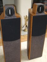
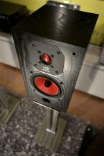
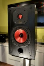
This is a pair of Merlin 3B+ speakers made in Rochester, NY circa 1990. These were given to me by a former co-worker, whose wife was tired of looking at them, and thought they were too big. I gladly helped them solve the problem.

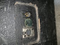
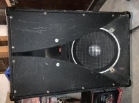
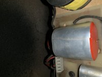
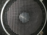
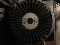
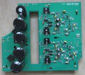
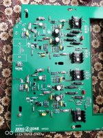
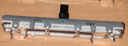
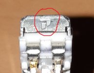
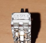
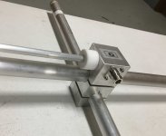
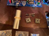
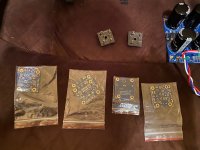
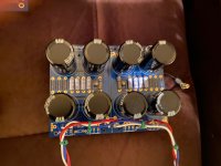
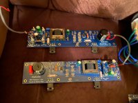
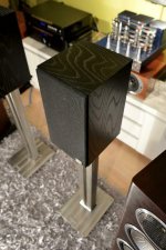
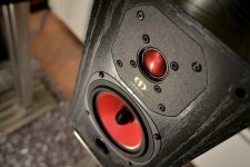
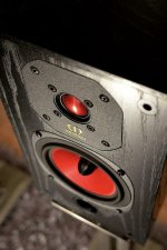
The original foam covering had completely disintegrated, the wood finish had some minor damage, one of the woofers had come disconnected, and the midrange and tweeter pots needed some cleanup. The bottoms are loaded with sand, and they weigh over 100# each. These were a pretty serious pair of high end speakers that retailed for close to $1000/pr, and still sound pretty amazing even by today’s standards. I owned a pair of the larger Merlin 4s years ago. I cured the performance ills, sanded and re-oiled the oak caps, and re-wrapped the tubes with 1/4” 30 ppi filter foam. ~ $45 of materials, and they’re back to looking like new.

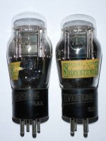
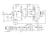
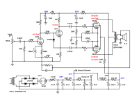
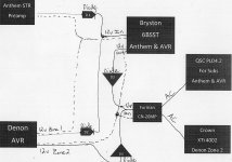
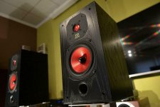
At some point I may eventually pass these on to one my kids who would appreciate them, but for now the Merlins reside in my basement system, and sound great driven by the small Stromberg Carlson ASR-120 tube amp I refurbed last spring.


000_3918.JPG 000_3921.JPG 000_3928.JPG 000_3939.JPG

000_3940.JPG 000_3941.JPG 000_3942.JPG

TPA3251 2Ch Amplifier Board DIY Design (Compact size/Amazing Performance)

Hi Guys,

Glad to share your guys with my customized DIY design - TPA3251 Amplifier Board for DIY Application.
this AMP and SMPS were released to my friends a few months ago and also have been used into their project successfully.

As your guys already know,the TPA32xx series chip have a lots of improvements,it features an advanced integrated feedback design and proprietary high-speed gate driver error correction to allows ultra low distortion. it attract many DIYer to start his own design to enjoy the excellent performance and also more and more companies have involved this chip into their product.

Key Features of My Design
  • Enhanced design with very low output noise (62uV/A-weighted) and lower THD+N (0.0015%/20W/4ohm)
  • Fully differential layout design for better noise cancellation
  • Smaller and Compact size(105mm*90mm*36.5mm – L*W*H)
  • Additional power ON/OFF reset circuit for Pop noise suppression
  • BTL configuration only for best audio performance
  • Single supply voltage range 24V~36 V(UVP:24V)

Full Project Detail:TPA3251 2ch PurePath™ Ultra-HD Class D Audio Amplifier

Performance Measurements Detail:
Audio Performance Measurements_EAUMT-0140-2-A
Audio Performance Measurements_TPA3251D2EVM
Audio Performance Measurements_TPA3251D2EVM_vs_EAUMT-0140-2-A

Attachments

  • EAUMT-0140-2-A_45°.jpg
    EAUMT-0140-2-A_45°.jpg
    653.2 KB · Views: 4,183
  • EAUMT-0140-2-A_Front.jpg
    EAUMT-0140-2-A_Front.jpg
    661.6 KB · Views: 4,084
  • EAUMT-0140-2-A_Back.jpg
    EAUMT-0140-2-A_Back.jpg
    593.5 KB · Views: 3,971
  • THD+N_vs_output power.jpg
    THD+N_vs_output power.jpg
    451.3 KB · Views: 3,917

[WTB] CBT24K speaker kit - prefer unbuilt

Looking for a pair of the Don Keele CBT24K speaker kit that used to be offered by parts express. It went NLA a few months before I was going to buy a pair. Interested in an unbuilt set, but will consider assembled if the price is right. I figure there have to be a few sets in garages out there that just never got built.

Please let me know what you have. Thanks!

Got my first Karlson! Europe made K15 clone

I always wanted to try a Karlson, what it sounds like. But it was down low on my project list. Therefore I got excited when I saw one for sale, as they seem to be rare in Europe and almost unobtainium in CZ. For ca 70 Eur I got this German made K15 clone. The speaker inside is DAS BI-30 15" speaker, it must be really old. The box itself looks very well made from plywood. There is some kind of crossover inside, throught the hole I could see two caps and one coil.

It is supposed to be fully functional, I need to replace the XLR connectors by Speakons and do some listening and measurements.

Attachments

  • C4BFA638-91B1-43C0-83FD-E30FF83AA9F6.jpg
    C4BFA638-91B1-43C0-83FD-E30FF83AA9F6.jpg
    1 MB · Views: 778
  • 2338EAC9-AE99-4580-AF3A-88A0EFCCB319.jpg
    2338EAC9-AE99-4580-AF3A-88A0EFCCB319.jpg
    1 MB · Views: 772
  • A13A1B76-867E-4B76-8709-6E66B1FC4D8D.jpg
    A13A1B76-867E-4B76-8709-6E66B1FC4D8D.jpg
    557.3 KB · Views: 743
  • 64BA3AFD-2C94-44D7-A31E-59CB81FA33F0.jpg
    64BA3AFD-2C94-44D7-A31E-59CB81FA33F0.jpg
    916.3 KB · Views: 685
  • 9409C0F7-D9FA-4310-AEED-FD2F1D11156D.jpg
    9409C0F7-D9FA-4310-AEED-FD2F1D11156D.jpg
    1.1 MB · Views: 689
  • B85F370D-6149-4F9C-B3BE-725BF25C7B84.jpg
    B85F370D-6149-4F9C-B3BE-725BF25C7B84.jpg
    817.4 KB · Views: 291

How to connect a wireless microphone receiver to a portable speaker aux input

How to connect a wireless microphone receiver to a portable speaker aux input

Hi. I'm a bit clueless when it comes to audio connections, so forgive me.

I have a wireless microphone receiver for exercise instructions. It has an XLR balanced output, and a 1/4 inch jack unbalanced output. I think the outputs are mono since there is only one actual physical microphone.

I have a bluetooth rechargeable speaker, with an "aux" 3.5mm stero input.

I would like to use the speaker with the receiver.

I tried a guitar lead with a 1/4inch to 3.5mm mono converter. A multimeter showed electrical connectivity to be fine for these to. But there is no signal at all from the speaker.

I also have a twin 1.4 inch jack to single 3.5mm stero jack audio cable. If I connect one of the 1/4 inch jacks to the receiver, I do get microphone audio from the speaker. But this leaves the other 1/4 inch jack unconnected, so it's noisy. Plus, I suspect I am only driving one of the speaker's stereo channels this way.

What's the simplest way to connect the two? I'm not sure if I need a pre-amp or not. The manual for the receiver says it has an audio output of 150mv. I do have a powered "Sideman SM-3 Parametric Equalizer" unit I could use. I'm not sure if it is a pre-amp, but it does seem to give a lot of signal boost.

Thanks for any advice.
Mark

FS: NAIM NAP-200 Clone Kit

I’m offering a DIY Amplifier based on the NAIM NAP 200 ( the unequipped Boards I bought in Shanghai) almost completely assembled, just 4 pieces 47uf / 63V capacitors are missing. All semiconductors are original Motorola, Zetex and Sanken. Resistors from Yageo and Dale. Power transistors are NOS Sanken 2SC2922 including the matching micas. The MJE243 & MJE253 are Motorola. The ZTX753 & ZTX653 are Zetex the remaining are from Motorola. The 2N5089 (bias) and the 2SC2922 are not soldered because they are soldered on the underside of the board. The 4 main capacitors are 15000uF/50V from Jamicon. Both Toroid’s pri 2 x 115Vac, secondary AC27V-0-AC27V each 200VA brand-new. Toroid’s with electrostatic shield made by Sedlbauer/ Germany. Toroid dia:110mm height:53mm weight 2,2kg. Naim PCB size: 280mm*235mm. Output Power: 75W+75W at 8ohm load. I have 2 Sets available. Asking 150 Euro + Shipping from Germany + 4% Paypal per set. PM me if you are interested.

Attachments

  • Naim NAP200 (10).jpg
    Naim NAP200 (10).jpg
    349 KB · Views: 354
  • Naim NAP200 (8).jpg
    Naim NAP200 (8).jpg
    436.6 KB · Views: 335
  • Naim NAP200 (5).jpg
    Naim NAP200 (5).jpg
    579.2 KB · Views: 540
  • Naim NAP200 (6).jpg
    Naim NAP200 (6).jpg
    502.3 KB · Views: 354
  • Naim NAP200 (7).jpg
    Naim NAP200 (7).jpg
    442.1 KB · Views: 300
  • Naim NAP200 (9).jpg
    Naim NAP200 (9).jpg
    352.3 KB · Views: 220
  • Naim NAP200 (4).jpg
    Naim NAP200 (4).jpg
    612.5 KB · Views: 243
  • Naim NAP200 (2).jpg
    Naim NAP200 (2).jpg
    390.1 KB · Views: 226
  • Naim NAP200 (3).jpg
    Naim NAP200 (3).jpg
    493.9 KB · Views: 226
  • Naim NAP200 (1).jpg
    Naim NAP200 (1).jpg
    283.5 KB · Views: 228

Sound is not "even"

Hello,
I have a problem that I don't know how to solve. For some reason I can't get "even" sound. By that I mean some songs vocals are less loud than other parts. I have attached two audio files. First one is PC>T.Racks 4x4 miniDSP > T.Amp E-800 Vocaroo | Online voice recorder. Another one PC>T.Amp E-800 Vocaroo | Online voice recorder. Song link Search | Universal Production Music. Can someone explain what is going on and how to solve this? As much as I understand I lack output from my primary source (PC), which Impedance or vRms?
Cheers,
Entas

Sherwood EQ-1330 potentiometer

Hi to all, I am currently in the process of restoring my old audio gear starting with this graphic equalizer. This unit still functions but the potentiometers are already very noisy and does not slide smoothly. I would like to replace them with new ones but the manufacturer is not printed or embossed on the body of the potentiometers. They may be Alps, but I really cannot tell without the manufacturer's name on it. Does anyone, by any chance, know the brand of this Japanese-made potentiometer? I have attached three photos and one of the views is of the logo that is embossed on the end of it (circled in red), while the word Japan is on the other end.

Attachments

  • pot_0353.jpg
    pot_0353.jpg
    231.3 KB · Views: 77
  • pot_logo.jpg
    pot_logo.jpg
    78.7 KB · Views: 83
  • pot_japan.jpg
    pot_japan.jpg
    86 KB · Views: 83

Worth replacing 2N5210 & 2N5087 transistors?

Hi there -

I have a nice little Plinius IIc that I am about to recap. There is a bank of 20-odd caps to replace in the power smoothing section alone.

This little pre is fitted with the 2N5210 & 2N5087 - its a little old now - from the mid-80's. There is a bit of hiss/noise in the phono sections but admittedly I havent tested it with a signal yet to really check out the S/N ratio there.

Are there any modern small signal trannies around that could be subbed in to replace these trannies that anyone is aware of? Some preliminary searching reveals that KSA992 & KSC1815 could be good subs?

Also, in the output section - the originals were replaced with B547B & B556B. I would also prefer to replace these with a more "hifi" sub if I can (or need to), but it may be difficult to find replacements with the same voltage specs (from what I have seen). I dont have the SM or schematic, so its impossible to tell what the originals were that were replaced here.

FM transmitter antenna help?

Can anyone tell me about this antenna I have? I've never seen one like it and don't know who made it. I'm using it with an R.V.R TEX30LCD exciter.

I've set up a temp drive in movie and this is the transmitter we have. It can do 30 watts, but found that even 16 watts caused all sorts of nasty noises in my audio gear. Backing it down to 0.9 watts does the trick and covers more than I need.

But what about this antenna? I don't know the type. Should it be mounted horizontally like a Yagi? Why does the driven element look like it's grounded at one end? It seems to work well, just curios about how it's supposed to be used.

Note: In the first picture were you see the letter D in the tube that's a sticker that says DOWN. I have used it with that down, but it didn't seem to matter.

Attachments

  • antenna_1.jpg
    antenna_1.jpg
    32.4 KB · Views: 169
  • antenna_2.jpg
    antenna_2.jpg
    39.2 KB · Views: 173
  • antenna_3.jpg
    antenna_3.jpg
    20.2 KB · Views: 173
  • antenna_4.jpg
    antenna_4.jpg
    46.9 KB · Views: 180

Ah Tjoeb Tube CD player

For sale cd player that I dont use now for some time.It put this on some mfd board,the tubes are now superb 6n23p silver shild(payed 90euro),I have put all new capacitor Panasonic fc,the coupling are mundorf supreme and evo oil and Arcotronics.Power cord is Ah Tjoeb Direct AC.Player hase original remote,ewerithing work as it should.The volume on remote works perfect.This us player for someone that can put together nice enclosure and made some further mods if he wish.But the player already sounds superb.The orice would be 150 euro plus shipping inside EU.The player is havy,so shipping will be around 30-40euro maybe more.

Attachments

  • 20200823_124029.jpg
    20200823_124029.jpg
    1,016.1 KB · Views: 151
  • 20200823_124038.jpg
    20200823_124038.jpg
    1,000.2 KB · Views: 150
  • 20200823_124042.jpg
    20200823_124042.jpg
    1 MB · Views: 143

500K Volume Pots!?

I'm in the planning stages of a 6AQ7 PP stereo amp with 6DJ8s up front. I'm using the transformers from an old Nutone stereo/intercom, and I'm planning to follow the power section schematic. It calls for a 500k volume pot, and that's a rare beast these days. I should say that the original front end in the Nutone had 2 x 12AX7s per channel. The new circuit will use one 6DJ8 per channel. Do I really need a 500k pot? I'm used to matching pots to pickups on guitars, and the pot affects tone. Would that be the case here?

selector-switch (single ended): better to switch ground, too?

sorry for this, but I'm on this build and I want to make it "as simple as possible but not more".

My source-selection will be a nice, simple (swiss 🙂 ) selector-switch. Should I make it a 4-poles switch, and switch the grounds too, or is it sufficient to only switch the signal and thus use a 2-pole switch?

thanks!
david

Creating Own Parts in LTspice

Hello,
I have created a schematic symbol in LTSpice from a circuit. I've stored the original spice list in a folder in the LTSpice directory in Documents.

When I create a circuit, I can call up my schematic symbol and place it into the main schematic i.e. its shows up in the LTspice 'Select Component' tab.

However, when I try to run the sim, I get the following error

'Missing Schematic(s) of the hierarchy: myfilename'

then

'Trouble Generating Netlist . . .etc'


So, I think what's happening is that the symbol is not finding the associated schematic. Where should I save it? I'd like to be able to use the part cross all my directories etc.

I have 'The LTSPICE IV Simulator' book by Gilles Brocard, pages 345 to 352, and followed it as best I can but its not really clear on this point.

Thank you

Port Tube, Volume Thiele / Small

First I apologize as I am sure this question has been asked and answered, I simply cannot find it anywhere (Probably am not constructing the correct search string).

I am designing cabinet for a FRFR guitar speaker. My question relates to the port tube.

With Thiele / Small the volume of free air within the cabinet seems to be crucial.

The walls of the port tube do indeed take up volume within the cabinet.

Question: Does one subtract the volume introduced by the walls of the portion of the port tube that is sticking into the internal area of the cabinet from the internal volume of the cabinet?

I hope I am making myself clear.
Volume of a cylinder: Volume=(Pi*Radius^2*Length);
Where:
- Radius^2 means Radius Squared.
- Length is the length of the port tube that is sticking into the cabinet.

So the internal volume of the cabinet consumed by the port tube walls is:
(Pi*((OD/2)^2)*Length)-(Pi*((ID/2)^2)*Length).

Note: My port tube is straight on both ends (no flanges).

If one wants to reply with something like 'It is negligible, don't worry about it' save your time as I am an extremely anal individual! 🙂

Thanks for any assistance.

Computer internal wiring

I'm building a pc for playing audio and also as a htpc as a second role-I changed the power supply to a high quility low ripple one which really improved the sound (im running electrostatic speakers so small changes do tend to make a difference better or worse) is it worth trying to get special wiring to improve the electrical voltage isolation or anything like that or is that a waste of time?

Klipsch R-115sw and high pass filters

I just bought this from Emile off the Klipsch fourm. Great sub. And Emile , like always, treated me very well in this deal.
What I’d like to do is install a high pass filter before the amp, maybe 15hz. So I can help it live a happy and healthy life without sending stuff into the amp that it can’t handle. I don’t really want to use a dsp. I do have a few of the none HD 2x4 Dayton dsp units. I will if I have to. But really want it to be a set and forget and no power to worry about.
So I guess I need a passive crossover for this. My denon does not have anything in the setup for the sub outs for doing this. Just a regular crossover points for the low pass and high pass for the other speakers. You’d thing they would start to add this into HT receivers?

Cleaning and lubricating pots and faders on mixers

Hi.

I have some mid-level DJ-mixers that are 10-20 years old. Some work fine and some have noise faders and pots.

Getting the correct replacement-parts are probably not cost-effective.

I've tried contact-cleaner, but read afterwards that its a really bad idea on pots because it may damage the tracks and also it removes any lubrication.

When the lubrication is removed on (cheap) pots and faders the "feel" becomes very bad. Furthermore I read that the missing lube will accelerate wear and tear of the tracks.

I know that some pots are beyond repair, but I would like to give it a try.

So whats your best ideas without resorting to specialty products that are not commonly available?

I saw one suggestion for:
  1. Disassemble if possible
  2. Cleaning with contact-cleaner
  3. Gently remove cleaner agent
  4. Lube with small amount of petroleum jelly, - also on tracks?
  5. Maybe use a very small amount of PTFE spray lube on the moving parts.

Kind regards TroelsM

Accuphase Xe350 clone amplifier Noise/Buzzing problem

hi everyone,
I need some expert help. Problem is that whenever I connect RCA to any device the buzzing, noise starts coming from speakers. There is less noise when only one input is attached. If there is no connection, it almost does not exist.

I disconnected the input ground and negative path with a 10 ohm resistor. But there was no change. TL082 replacement to OPA2134; no changing.

What solution do you think I should find?

Thank you in advance for your help

Attachments

  • IMG_20200720_012749 (Özel).jpg
    IMG_20200720_012749 (Özel).jpg
    726.4 KB · Views: 363
  • IMG_20200815_233049 (Özel).jpg
    IMG_20200815_233049 (Özel).jpg
    900.9 KB · Views: 352
  • IMG_20200814_033147 (Özel).jpg
    IMG_20200814_033147 (Özel).jpg
    606.8 KB · Views: 317
  • IMG_20200822_013707 (Özel).jpg
    IMG_20200822_013707 (Özel).jpg
    663 KB · Views: 334
  • TB2fOZ8uNXlpuFjSsphXXbJOXXa_!!24102882.png
    TB2fOZ8uNXlpuFjSsphXXbJOXXa_!!24102882.png
    62.2 KB · Views: 372
  • TB2Sqyeu88kpuFjSspeXXc7IpXa_!!24102882.jpg
    TB2Sqyeu88kpuFjSspeXXc7IpXa_!!24102882.jpg
    931.2 KB · Views: 322
  • TB2YupZuYVkpuFjSspcXXbSMVXa_!!24102882.jpg
    TB2YupZuYVkpuFjSspcXXbSMVXa_!!24102882.jpg
    809 KB · Views: 250

DIY Subwoofer

I built a dual passive radiator single active driver subwoofer using a well-established 12" Peerless XLS design (2-12" PR's and 1 -12" active driver). The unit is equipped with an Adire ADA1200 plate amplifier. I could not get the brand new amp to work (Adire was out of business by then), and I ended up having a local shop here in Vancouver, BC attempt to repair the brand new amp... For a myriad of reasons, life, health, etc., etc., I have never actually used it-ever.

The box is heavy, and really well built. It measures about 18.5" x 18.5" x 19" deep. I have removable grills (black cloth) for all three sides.

If you are in the lower mainland of B.C., it is yours for free. It is spray painted satin black, and is in very good cosmetic condition.

Newbie 832A Amp Questions

This is my third foray into the world of hi-fi-ish amplifiers, the first two being simple single ended affairs. I've collected a handful of 832A and GU32 tubes and really like the look of them. I plan to run them cathode biased to keep things simple. According to the RCA datasheet, the grid resistors should not exceed 50k per section, but I have seen audio designs as high as 390k. What do you guys think about this?

For the front end, I want to use the 9002 tube with a 6C4 phase splitter. I came up with 2 options.

AC coupled:

attachment.php


and DC coupled:

attachment.php


For the AC coupled design, I think I picked a pretty reasonable operating point for the 9002 tube, but then there's that 0.1uF coupling cap. However, I got that 0.22uF cap coming off of the wiper of the potentiometer. I've seen opinions stating that the 0.22uF cap is unnecessary, and I've also read that it's good to keep DC off of the pot to prolong it's life. What do you guys think?

For the DC coupled design, the operating point of the 9002 tube is kind of wonky, I think. Also, will the protection diode on the 6C4 be necessary as I have the 6CG3 diode in the power supply providing a slow start-up?

I have absolutely no reason for the 6CG3 diode except to drop a few volts and to increase the tube count. I have plenty of filament current available so why not? More tubes = more better, right?😀

Thank you all for your time.

Attachments

  • AC Coupled.png
    AC Coupled.png
    207.9 KB · Views: 1,102
  • DC Coupled.png
    DC Coupled.png
    212.5 KB · Views: 1,419

hacking the power supplies

A while back I ask here in the forum if I can parallel two power supplies to power the chipamp. One power supply had just perfect voltage, but not enough current, there was distortion in the peaks in dynamic music and trafo itself was getting warmer and warmer.
Luckily, I had two identical ones, so I paralleled them, and life is good. Highly recommended.

However, I have many other projects. Here are some other tricks I learned.

I had quite a powerful 12 volt dc switching power supply, so I tried to use it as heater source for tube amp (two stereo 6 volt section in series). It worked, but I was hearing some buzzing sounds inside the tubes, and that is even without high voltage. I always preheat first. So I was wondering how to get rig of this buzzing, which, I am not sure, may be harmful to the filament. You can not connect any big cap to switching supply, it shuts down. However, if you treat it like its high frequency AC, and you put full diode bridge, then you can place any capacitor value after the bridge, and truly create DC. You may end up with slightly different voltage, but for the heaters, that is perfectly fine. Remember, you are not galvanically isolated.

In other case, I had two 19.5 volt DC switching supplies, so I did the same, placed full diode bridge to each, then big caps for filtration (do not remember now, can check later, but a lot), connected minus of one to plus of the other to create ground, and now I have +/- ~19 volts DC, perfectly filtered, for chip amp. Remember, no galvanic separation. The other thing I did was I chopped of the AC lead, and connected both to one AC power outlet, as not to have two power cords. That would be awkward to turn it on at the same time.

Ok, one more.
I was experimenting with tube amp, and I needed high voltage AC of ~250 volts. I had no such transformer around, so I came up with this neat solution. I had plenty of transformers, which are 120 volts in, 30 volts out. From old amps. So I connected first trafo to the wall, normally, took 30 volts AC and plug it straight to 30 volts AC on second trafo, and since second trafo had two secondaries to allow 120/230 option, I wired it to give me ~ 230 volts. Good enough to rectify and use it for tube amp. Works like charm. And now we are galvanically separated, even double!

Ok, enough for now. Disclaimer, I am no expert in this, just diy fanatic.

Fake transistors from eBay

So I got these to have the Bryston with the same transistors on both sides
8 Pairs | MJ21193 + MJ21194 PNP + NPN Silicon Power Transistor Original MOTOROLA 348643461001 | eBay
Only to find they were fake. there is a small piece of silicon inside, much different to the authentic ones. I had sparks, fire, nastiness all over. Hopefully the boards are repairable. Buyers beware.
Seller did refund, he might have been scammed when sourcing parts as well, just source your parts from reputable sources.

Attachments

  • IMG_20200725_204618976.jpg
    IMG_20200725_204618976.jpg
    666.2 KB · Views: 1,789

New Jordan JX150/A.C.Ribbon Design

I thought I'd share details here of my latest loudspeaker project.

Jordan JX150NG
Aurum Cantus G2si
2nd order H.P.
3rd order L.P.
Crossover 3.5kHz

The passive crossover was designed using frequency response, impedance and phase measurements of the drive units in the
enclosure. Phase tracking through the crossover region is as close as I could get it whilst keeping the high pass section 2nd order to avoid the need for a second capacitor. The jx150ng response starts to wiggle above 2.5kHz which didn't help so I aimed for close phase tracking through, and either side of the crossover rather than a deep reverse null. I Later fine tuned the inductor and resistor values to account for actual measured capacitor values. The high pass capacitor is teflon film/foil.

The metal grill has been removed from the ribbon for improved transparency, my thanks to mikelm for this suggestion as it makes a remarkable improvement. The treble enclosure sits on the main enclosure via a concealed fixing which both holds the unit in place and allows some forward/backward movement for fine tuning of phase via adjustment of the vertical offset should it be necessary. At present the offset is set for best overall phase tracking following my simulations and I haven't felt any need to alter this but according to simulation forward adjustment of 1/4" from its current position should offer a deep reverse null should I decide to see which actually sounds better.

The crossover is situated in a separate compartment in the base of the main enclosure which is 3/4" ply with a ceramic lining and cross bracing for rigidity. At 25L (sealed) it is on the small side for the JX150NG but at 25kG it is already heavy so rather than accommodate the reduced size by lowering the Qts of the Jordan via a resistor across its second voice coil which would have reduced efficiency, the response was equalized to remove the resultant slight bass lift of 1dB or so via a resizing of the input capacitor on the amplifier input, preserving efficiency and reducing the amplifier's work load. The resulting bass roll off integrates well with a subwoofer, in this case at 65Hz.

Subjectively there is a lovely sense of precision plus resolution. Depth and width spacial information is excellent and the treble is extremely light and airy. It has incredible ambience and is a real joy. Instruments and voice are at least as focused as my trusty Quad ESL63s, and in some ways actually better. Despite the less than ideal Jordan roll-off the midrange is really good too with clean detail and plenty of it without any noticeable transition to the treble...to my relief.

Possible future improvements?
1. Maybe swap the laminated steel bass inductors for air core. These are 0.9mH and 0.56mH. Suggestions here would be very welcome.
2. Possibly replace the MOX resistors in the treble section with something else?

Thoughts/suggestions welcome.

Tim

Attachments

  • DSCF4474.jpg
    DSCF4474.jpg
    463.2 KB · Views: 748
  • DSCF4480.jpg
    DSCF4480.jpg
    504.4 KB · Views: 730
  • IMG-20180501-WA0021.jpg
    IMG-20180501-WA0021.jpg
    473.9 KB · Views: 720
  • FR.jpg
    FR.jpg
    65.9 KB · Views: 706
  • Imp.jpg
    Imp.jpg
    58 KB · Views: 690
  • Filter.jpg
    Filter.jpg
    57.8 KB · Views: 202

Rockford fosgate 750s

Good day gents,
I have a quick question/s about setting bias on what I believe is a 750s amplifier.
Amp came in with a badly burnt power supply and right channel. Both were rebuilt with new parts, amp is up and running thus far.

I’m setting the bias via the voltage across the source resistors. With the amp on start up, the voltage across the resistor is 5mV.
As the amp warms up it goes up and settles around 11mv. If I try to lower it however it remains at 11mv, if I go beyond the halfway setting on the pot, it increases.

For now I’ve set it at this (just under the halfway point in the pot) and have it running.
I compared it with the left channel, but the left channel remains constant at 0mv ( at start up and warm).

I belive this should be ok, but just wanted to see if anyone had similar experiences.

Attachments

  • 6C2554EE-A9DC-4DA8-84BC-2781C3BED0D4.jpg
    6C2554EE-A9DC-4DA8-84BC-2781C3BED0D4.jpg
    1 MB · Views: 133
  • A9FA7813-D756-4C6B-B88A-420AC402C1DB.jpg
    A9FA7813-D756-4C6B-B88A-420AC402C1DB.jpg
    915.1 KB · Views: 101

FS: BG N Capacitors

I have eight original BG N 100uF 50V capacitors I purchased way, way long ago when I was building Peter Daniels gainclones. Included here is a pic I copied from the internet. I'll include real pics later today. I still haven't figured out a fair price for them so I'll see what interest they attract first.

Regards,
Dan

attachment.php

Attachments

  • BG N.jpg
    BG N.jpg
    33.5 KB · Views: 989

15" or 6x8" for open baffle

Hey. Thought i would ask your opinion on the importance of the bass driver(s) to be used in an open baffle application.

For context, the mid-range and highs will be played by drivers I already have: Audio Nirvana Super 10 CF (150 - 600 Hz) and 18Sound ND1480A on the XT1464 horns. Filters and EQ are managed digitally before DA conversion.

Alas, the lows are currently played by a sorry-*** old single 8" vented box. Using it is a crime and pretty much ruins the system.

After a lot of soul searching and thinking about potential cardioid setups, I have now decided, that midrange and the lower notes down to 40Hz will be open baffle with the option to include a sub for the lowest octave and cardioid experiments.

What got me was a review of the SoundKaos' open baffle model using a Beyma 18LX60/V2. That could work. But large drivers have heavy cones, which essentially limits the driver slew rate. Looking at cone weight and motor force, the CF10 has 5 times more power per weight. Even if you factor in the 4x difference in cone size, the CF10 would be able to move the same amount of air, but still around 25% faster. Odd.

This got me thinking about drivers with light cones, but low Fs and hopefully cheap. Visaton BG20 is one, so i thought having 6 of them on a circular baffle. The summed SD of six of them is equivalent to the Beyma, but the overall moving mass is more than 3x lower and driving force is more than 50% higher. Xmax of 4mm p-p is a problem, but absolute SPL on an 85cm baffle is still 102db at 40Hz. That seems adequate. Especially if a sub is added at a later date.

Also, both drivers need similar levels of EQ at the lower end, albeit the 18 has a lower resonance frequency and thus can play a little bit lower.

To illustrate the point i have added the room response curves and a kind of a slew rate calculation for an assortment of drivers.

Attachments

  • Annotation 2020-08-18 173040.png
    Annotation 2020-08-18 173040.png
    69.8 KB · Views: 492
  • SDslew.png
    SDslew.png
    17.6 KB · Views: 448

Chip Amp

For Sale:
I have a transformer, completed power supply, and two completed channel output boards from a Chimpamp.com inverted LM3886 chip based amp. I built this amp myself, first kit I ever built. Shortly thereafter I started on the SE path. It has sat on the shelf for a few years. I ran the amp from a CD for two songs this morning to make sure it operated and then dismantled it.


All I am selling is the transformer (22v+ / 22v- /160VA), the populated power supply board, the two populated left and right channel PCB’s, and the heat sinks. The wire is silver tinned wire. I left the boards soldered together.
All of the other items such as binding posts, RCA inputs, potentiometer, power plug, fuse plug, etc I am keeping for my parts bin. If you want to try chip amps this might be a place for a newbie to start.


$70.00 shipped in the US. Paypal works best.
Thanks.

Attachments

  • IMG_1500.jpg
    IMG_1500.jpg
    250.5 KB · Views: 234
  • IMG_1502.jpg
    IMG_1502.jpg
    270.2 KB · Views: 242
  • IMG_1503.jpg
    IMG_1503.jpg
    309 KB · Views: 232
  • IMG_1504.jpg
    IMG_1504.jpg
    287.8 KB · Views: 239

Replacing the ECL86/PCL86 with two tubes

I far far too many radios that use this tube and unfortunately they are practically unobtanium if you are dirt cheap as I am. So for the same price as one ECL86 from ebay I can buy two tubes, EL84 and a 12AU7

What I am trying to do is basically design a board that would hold two tubes and plug into a single socket of a ECL86.

Now some of you are already bashing their head on the subject of heater requirements... Yes it will be more. Marginably more. The EL84 itself already pulls 760mA at 6,3V, add the ECC83 on top and it would look like above an amp but not really. I plan to paralel the triodes within the ECC83 but only light up one triode at a time so really its more like 900mA give or take... I can live with that especially since in most of these radios I replaced the rectifier with diodes (indirectly heated from 6,3V.. So its perfectly safe and viable for me. And the though of having a non original part in there wont ruin it for me. After all its gonna be hidden in a wooden cabinet. And even if AM trasmission will be long gone I can still use the radios as just plain record players 🙂

My question is which triode would be the closest to the one of the ECL86? the 12AX7? 12AU7? 12AT7? I dont have an answer to this. Wich tube would fit the triode section of the ECL86?

Caspian CD Display Dim

(My initial post does not appear to be showing up. Apologies in advance if it does and I end up repeating myself.)

I have a Roksan Caspian CD player which according to sources on the internet has an inherent problem of dimming display. The unit's display had been replaced prior to my purchase, however over the past year it has indeed gone south again.

I have not found any diy solutions on the internet. Contacting both Roksan and service centers have resulted in requiring sending the unit in for estimate.

I use the player as a transport feeding a Perpetual Tech P3A dac. I am happy with the set-up, but it is getting long in the tooth and due for an upgrade. So I prefer not to invest much into the Caspian to fix the display. Unless of course I can dabble with it myself.

Any help would be much appreciated.

Ed

RH84 very high cathode voltage on EL84

Dear colleagues,

I've finished test build of RH84 rev.2 amp. I am using EL84 replacement tube, 6p14p. B+ is fairly close to the desired one 315VDC however, in one channel I got really high cathode voltage. After powering amp ir slowly raises to around 3-4 volts and than peaks up to 45-50V DC!

So what I did for tshoot: checked wiring 10 times, swapped tubes, swapped cathode capacitors and checked LM317 which somehow is not blown yet, checked zener diodes. Second tube has bias voltage around 8V DC so all other values will be checked later but this one makes me to turn off amp quickly to prevent any damage. I am out of ideas which component might cause this behaviour.

A link for amp schematics for reference.

RH Amplifiers: RH84 amplifier - revision 2


Thank you!

Strange new noise from speaker?

You can see my current setup in my signature, and just recently have been hearing a noise from my left speaker.


I believe its the tube amp as the noise presents while all inputs are off.
Nothing has changed in my setup for months, and know for sure it wasnt there before...


The attached mp4 was from my phone, and while you may have to crank up the volume to hear during play back is in real life barley audible from 10' away. Within a few feet is very pronounced.
* edit - I moved the microphone from tweeter to mid-range and back and is why there is a change in pitch...

Im wondering what electronic part may make this noise or how to start tracking down the culpret...

Attachments

  • My Recording_3.mp4
    181.1 KB

For Sale GE Super Radio III

For Sale GE Super Radio III


I am the original purchaser of this radio. The radio hasn’t been used very much maybe 15 hours or so. Been sitting on the shelf in its original box and packing for a few years. I'm moving again and cleaning house.


The radio is super clean. Battery compartment is clean, never used. I plugged it in to make sure all is well. Only item is volume potentiometer is scratchy. I don’t know how but it is. Cleaning or replacing wouldn’t be an issue. I have all the original box, packing, user manual.
$60.00 shipped in the US. Paypal is best.
Thanks.

Attachments

  • IMG_1505.jpg
    IMG_1505.jpg
    276.9 KB · Views: 152
  • IMG_1506.jpg
    IMG_1506.jpg
    237 KB · Views: 150
  • IMG_1507.jpg
    IMG_1507.jpg
    304.8 KB · Views: 155
  • IMG_1508.jpg
    IMG_1508.jpg
    415.2 KB · Views: 148

Rudi_Rozek Amp Camp Boards with other parts (Stuffed and 100% working)

For sale are two fully stuffed and heatsink mounted Amp Camp boards designed by Rudi Rozek. I have built 8 amplifiers out of Rudi’s boards but cannot finish this project as I just bought a new house. These boards and parts are a big improvement over the stock 1.6 which sounds great as is!

The boards feature Tungstenaudio’s modifications and parts as well as Jason Kuetemann’s CapMX power supply.

The heat sinks measure 9 inches deep x 4 inches height x 3 inch wide fins.

I will also include a pair of RCA inputs and two pairs of banana posts.

I am asking $200 shipped CONUS.

Attachments

  • 06239DBB-4DCF-4BEB-B279-75C43A19D538.jpg
    06239DBB-4DCF-4BEB-B279-75C43A19D538.jpg
    1,003.5 KB · Views: 287
  • F21062F5-AA24-4C2B-9312-11EAED8FEF54.jpg
    F21062F5-AA24-4C2B-9312-11EAED8FEF54.jpg
    1 MB · Views: 272
  • E7FE2B6A-49CF-43E3-AA17-546D79A70BB1.jpg
    E7FE2B6A-49CF-43E3-AA17-546D79A70BB1.jpg
    987 KB · Views: 302
  • 9A79BEA3-118B-4F31-8BE6-F27866F064EB.jpg
    9A79BEA3-118B-4F31-8BE6-F27866F064EB.jpg
    1.1 MB · Views: 252

M2x Parts Sale

For sale is almost all you need to build an M2x amplifier with all parts 100% working. Just get your chassis and a few more parts and you are good to go.

I am selling these parts for a friend that wanted to convert his amp into an F5 Turbo and he had the m2x in a 5u chassis.

What you get is:

- Both PCB boards fully stuffed (Tucson boards installed)
- Power Supply board with 60,000 per rail
- 35A Monolithic Bridge Diodes
- Antek AS-4218 Transformer with Cover
- 2 extra CL-60
- the spare unused daughter boards
- Spare roll of shielding for the Edcors (if you need it)
- Keratherm Pads (not shown in pics)

I am asking $260 shipped CONUS only. I spent around $400 for all of these when I built the amp.

Attachments

  • IMG_1248.jpg
    IMG_1248.jpg
    834.1 KB · Views: 536
  • IMG_1247.jpg
    IMG_1247.jpg
    721.5 KB · Views: 514
  • IMG_1246.jpg
    IMG_1246.jpg
    803.1 KB · Views: 520
  • IMG_1245.jpg
    IMG_1245.jpg
    670.4 KB · Views: 498
  • IMG_1244.jpg
    IMG_1244.jpg
    753.8 KB · Views: 502

12v trigger from 2 pre-amps to 1 Amp, plus more

I have a couple 12v trigger issues I’m dealing with.

I have an Anthem STR Pre-amp with my Front Right and Left speakers connected to a Bryston 6BSST amplifier. The Anthem supports Home Theater Bypass but is in standby mode when HTB is activated. I need the same Bryston amp to turn on while the Anthem is in standby. A 12v Y-cable with a couple diodes should solve this issue.

I have a couple pro amps without 12v triggers and want to use a Furman CN-20MP to turn them on. The Bryston will provide the 12v out to the Fuman 12v in for the subs.

I have a second pro amp that powers my house in-wall and outdoor speakers. Currently my AVR trigger out 2 is set up for zone 2. The trigger 2 12v out is connected to a Furman CN-20MP to turn on the Crown amp to drive my whole home speakers. I want to use the same CN-20MP to turn on a QSC amp to drive my subwoofers. The Bryston 6BSST will provide the 12v pass-through.

Does my attached diagram look correct to accomplish what I want while protecting back-feed?

I'm confident the y-cable to the Bryston will be fine but want to be sure on the other since there may be times when both trigger 2 from the AVR and the Bryston trigger out will be active.

Thanks.

Attachments

  • 12v_Trigger_Y_Cable_x2.jpg
    12v_Trigger_Y_Cable_x2.jpg
    174.9 KB · Views: 137

Beveridge 2/2SW membrane film material?

Hi all-

Before it is lost to the mists of time can we document everything we know about the membrane material Harold Beveridge used? What kind of plastic, how thick is it, is it metallised on one/both sides, etc.

Happy to report my 'new to me' 2SWs have been working good since I got them going. Amazing speakers. Easily the best I have ever heard.

Transformer alignment check

Hi all
For some time, I've been working on a 300B SET amp from this schematic DIY 300B Single-Ended-Triode (SET) Hi-Fi Amplifier Project. Unfortunately, I never managed to get the hum out of it, which I think was due to limitations imposed by my unconventional chassis. I've therefore decided to pull it apart and rebuild it on a more normal chassis with a better layout. Given this experience, I'm somewhat paranoid about building in hum now though, so wondered if I could get people to check my transformer alignment before I bore any holes.

The attached photo is my proposed layout. The large Edcor box at the bottom left is the power transformer. The two smaller Edcor boxes above are the 5H power supply smoothing chokes, and the grey boxes at the right are the output trannys. The two gold boxes are the 200H chokes for the pre-amp supply. I'm intending to hang them in the pictured orientation upside down from the top plate under the the output trannys.

Is this a decent layout for avoiding inductive problems, and if not, what should I be doing differently?

Thanks in advance.

9EK3FmKHy8bnSG8p7

Monitor Audio Ruby 3 - Test Reviews and Part List wanted

On the web I don't find this. In the attachment some images.
Thanks for advices.

Attachments

  • $_uz (2).jpg
    $_uz (2).jpg
    78.5 KB · Views: 171
  • $59 (2).jpg
    $59 (2).jpg
    78.8 KB · Views: 225
  • $_5p (2).jpg
    $_5p (2).jpg
    58.7 KB · Views: 136
  • $_5l (2).jpg
    $_5l (2).jpg
    73.3 KB · Views: 162
  • $_o9 (2).jpg
    $_o9 (2).jpg
    66.9 KB · Views: 169
  • $_59 (1).jpg
    $_59 (1).jpg
    73.6 KB · Views: 164
  • $_53 (1).jpg
    $_53 (1).jpg
    56.7 KB · Views: 169
  • $_5z (2).jpg
    $_5z (2).jpg
    69.8 KB · Views: 152

Behringer B3030A - Mods

Hi all,

I've had a pair of the Behringer B3030A monitors for a while, and I quite like them. They sound pretty full-range, nothing really missing, and go pretty loud for the size of the box. I quite like them.

Naturally, I dismantled them.

Everything looks pretty good:
- Sensible electronics (though I'm not particularly experienced in that area)
- Solidly built MDF cabinet, with reinforced baffle around the midbass driver, around 30mm thick there.
- Decent drivers
- Chunky speaker wires

A couple of things I did note that might be improved upon:
- No internal bracing
- The 6" midbass driver has a fairly narrow window to the back of the cone, and the extra-thick baffle means I can barely get a finger to the cone.
- Connectivity. It would be nice to be able to connect a 3.5mm jack cable and play music, instead of messing around with XLR devices.


Note that I'm not going to advocate swapping drivers, cables, capacitors etc. There are better ways to spend money than a pair of esoteric capacitors with no measurable benefits. Some good whiskey has much a much better price to performance ratio.
Swapping drivers out is also a no-no. This particular driver complement demands a higher-than-usual crossover point, and dropping in a different set of drivers would mean a re-design of the crossover. You might as well just start from scratch.

So, on to the mods...
The slot ports go down the sides of the cabinet, exiting near the bottom inside, so cross-bracing the sides is difficult. However, it's easy to brace between the baffle and back panel. I used a 1.5" wide strip of 18mm plywood. Cut to about 133mm long, it wedges in nicely. Generous quantities of PVA secured it. The top and bottom panels have some extra blocks around the edges for support, and the midbass driver's shielded magnet is quite large, so I didn't bother bracing that way.

Next up, I took a sharp knife to the cabinet, and cut away a rough chamfer around the midbass driver. This took quite a while since the material is quite thick. Sandpaper smoothed it out with a slight round-over. Afterwards, I could easily get two fingers to the back of the cone, so airflow has been improved. Since the woofer is running quite high (3.4kHz), that'll reduce midrange reflections, too.

Lastly, connectivity. I've drilled a pair of holes in the bottom of each amplifier. On each speaker there'll be...
1x 3.5mm jack socket (input)
1x 6.35mm jack socket (output)

One side of the 3.5mm input goes to the input stage on the amplifier (or just to a couple of the XLR pins). The other channel goes to the new 6.35mm jack socket, which will act as an output to feed to the other speaker via a guitar cable.
With that installed on both speakers, either will be able to be used as the master speaker and feed out to the other one. I think the left speaker will be the master (personal preference), so the right channel of the 3.5mm input will go straight to the output jack.


I'm waiting on the connectors arriving so I haven't done that bit yet. As for the rest, I can say the sound has improved a little. There was some gain at the low end, to a point where I've had to use the LF rolloff switch to tame it a little. Hey, free headroom.
I haven't noticed any epiphany-like improvement to the sound. I think perhaps transients are a little sharper, but I could be fooling myself.

The improvements suggested probably make things better, and certainly don't make things worse. It's also cured the itch to open these up and see what can be done with them.

Cheers,
Chris

Digital Design M5 Power supply issue

Working on a digital design M5. When I got the amp, the outputs were shorted and driver board bad. I removed all output, rail rectifiers and driver board. No shorted mosfets in the power supply but the amp is in protect. Pulled all the mosfets in the power supply. Not in protect. Relay turns on. I've isolated the problem to one of the power supplies. I can load all the others and the amp turns on. No protect. All driver transistors check good and drive signal looks good to the gates. When I load it with the mosfets, the power supply is immediately in protect. The mosfets do not get hot or short. Any ideas?

JDS Lab Atom preamp, good measurements but weak power, why?

Hi, I hope you can clarify my doubts, i feel quite confused.

I bought a JDS Lab Atom, to use as a preamp.

The Atom is a small and inexpensive headphone amplifier and preamplifier, based on an opamp design, famous for its reference measurements (THD, noise, frequency response, SNR).

Before purchasing I asked JDS Lab and they assured me that the Atom, with its 8.6V output, would drive my Gamut D200i power amp very well.

But when the Atom arrived home, I found a thin sound, lacking in energy, lacking in driving power. A very small soundstage in both width and depth, an anemic sound, lacking body and fullness.

My DAC is a Bryston BDA coming out at 2.19V from its unbalanced outputs.


My power amp is a Gamut D200i in low gain mode, requiring 3,9V to reach its full power.


The Atom applies a gain of 4.5x, so 2.19 * 4.5 = 9.85V, well beyond my power amp requirements.


I compared it with a Mark Levinson 28 preamp that has a max output voltage of 6V and applies a gain of 12 dB (4x), so
2.19V * 4 = 8.76V.

Despite the theory to the contrary, the Mark Levinson (as well as all the other preamps I have) drives my power amp much more powerfully.

Depends on what? Since the output voltage is even higher in the Atom?

I then compared it with other preamps:

- ARC LS12;
- Project Pre Box DS2;
- Spectral DMC20S2;

Same story, weakness.

Finally i tried the Atom as an headphone amp and compared it to the "DOCET Cuffia AMP" headphone amp in driving my AKG K702 headphones.
AKG K702 headphones requires about 3,6V to reach a 115 dB SPL level; despite Atom amp output 9,85V, same story: weakness.

So I emailed JDS Lab, asking if it could be a low current matter (it otuput "only" 1W on a 32 Ohm load), but they replied that power only depends on volume (voltage).

I do not know what to think.

Someone can clarify me what is happening?

Thanks,

Marco

(sorry for my bad english)

Tube amp: Bring it back alive

Hello All,


I have an old handmade tube amp (EL84, 6CA4, 5814A) and due to a design flaw, the plus un minus cable of the speaker touched each other and kill one of the two output transformer... I don't want to ditch it so i corrected the design flaw but i need to find another (or compatible) output transformer, could you help me to source one or point me the right direction? Thanks!


Here are the specs i found:


Audax transformer
Type 50-60 (seems to be the size)
7000 ohms (@ 400hz?)


RS 123-7237 V78A01F OEP output transformer

Hi I was looking through RS components product line and found this cheap output transformer.
RS number 123-7237, OEP V78A01F

https://docs.rs-online.com/127f/0900766b8152890d.pdf

Has anyone tried one of these? RS offers free delivery in Australia making these a cheap transformer. The low frequency response graph looks like it was derived using a low Z source into the primary; it's primary inductance is only 19H, this may work OK with triode drive. I would like any reviews or comments.

Keep Covi-19 safe; my condolences to those that have lost loved ones.
from Ken Kranz in Adelaide Australia.

Subwoofer Efficiency is Mostly Irrelevant

Over on Facebook, there was a discussion about pro sound vs car sound subwoofers.

A lot of people were saying that pro sound drivers are better because they're more efficient.

I stated that subwoofer efficiency is mostly irrelevant.

For instance, if you have two drivers, and one has an efficiency of 80dB, and the other has an efficiency of 90dB, they will produce just about the same amount of SPL at low frequency if they're fed with the same amount of power.

This probably sounds nonsensical; you would think that the more efficient driver would be... more efficient.

But it doesn't work like that, for the most part. Because at low frequency, subwoofers are basically pumps. The size of the cone matters, and the power handling matters, but efficiency just isn't a factor for the most part.

In order to evaluate this statement, here's some data.

maxresdefault.jpg


In this corner is the Sundown SA-18 V2. It's a car audio subwoofer with low efficiency and a lot of displacement. Fairly typical for car audio.

20200721200145_Photo2-EminenceTG-NSW4018-8Woofer.JPG


In this corner is the Eminence NSW4018-8. It's a pro audio subwoofer with high efficiency and moderate displacement. In the realm of pro audio subs, it has unusually high displacement, but it's efficiency is typical.

The Sundown 18 has an efficiency of 87 dB: Sundown Audio SA-18 REV3 D4 18 Inch 750 Watts RMS Dual 4-Ohm SA Series Subwoofer

The Eminence has an efficiency of 96.6 dB: https://www.parts-express.com/pedocs/specs/290-5660--eminence-nsw4018-8-spec-sheet.pdf

Efficiency and box size are connected, per Hoffman's Iron Law. This mean that the LOW efficiency car audio sub needs half the space as the HIGH efficiency pro audio sub.

So, let's compare the output of two SA-18s vs ONE NSW4018 in the same box.

Note that a pair of SA-18s will set you back $700 while a single NSW4018 will cost you $580.

FiKmAm8.png


MgvYR4a.png


Here's the frequency response and displacement of ONE NSW4018 vs TWO SA-18s. The box is identical, the watts are identical.

Thought the Eminence is 9dB more efficient than the Sundown, the output at low frequency is basically identical, as one would expect. (Hoffmans Iron Law.)

There's a VERY noticeable efficiency advantage above 100Hz. The Eminence is much more efficient above 100Hz. But this is consistent with what I've proposed:

Subwoofer efficiency is mostly irrelevant.

If you want your woofer to play to 1khz or 2khz, you definitely want to examine the efficiency spec. But at 60hz? It doesn't really matter, for the most part.

One of the reasons that the Eminence is so much more efficient at 1khz his because the Sundown has a lot of inductance. Scott Hinson writes a lot of great stuff, and he observed that car audio subs often have higher distortion. I'd agree with him; the Sundown will likely have higher distortion than the Eminence. Non linear inductance leads to distortion, and considering the very high inductance of the Sundown, I'm willing to bet that it has higher non-linear inductance than the Eminence.

In Sundown's defense, keep in mind that distortion and excursion are generally correlated. IE, if your subwoofers are using up their xmax, you're likely to hear distortion.

Sundown has an advantage here: because it works in a box that's half as large, you can use two. And because you can use two, each woofer is only traveling half as far. This lowers distortion.

So there you have it:

The response shape of the two solutions is virtually identical below 80Hz. The Eminence is flatter, but only by about 1.5dB, which isn't going to be audible.

The Eminence has less inductance and an advanced motor, which is nice. But the Eminence costs nearly twice as much and it needs a box that's twice as big as the Sundown. The Sundown motor is fairly basic. But you can cram TWO Sundowns into a box that's big enough for ONE Eminence.

Basically:

There's no free lunch.

Convertering Speaker Level to Line-Level - Mixer

I have one of these:
Koch Dummybox Home - Koch Amps

Looking to get 2 more channels for an old vintage Stereo Mixer that puts out Speaker Level, but I'd like to convert it down to line-level.

The Koch works well, but I don't need all the bells and whistles, just want Line Output.

So I purchased 2 of these:
Parts Express 8 Ohm 100W Non-Inductive Dummy Load Resistor: Electronic Resistors: Amazon.com: Industrial & Scientific

Question;
Is the setup as simple as, hook up the dummy load and tap off in parallel for line level?
Or any recommended additional resistors or caps for protection/etc? This will be going into a Universal Audio Apollo Recording Interface.

I tried opening up the Koch to take a look, but couldn't tell for sure.

Just Bought Some Acoustat Model 3 Speakers

I got them at a local pawn shop for $500 plus CT sales tax, with a good return policy. They have the Medallion interface, black logo version. They look to be very well cared for. I have not got them home yet, probably won't till the weekend. In the meantime I am combing the Acoustat Answer Man thread. I must say I do not plan to do any of the big mods some of you guys do. I just want to make sure I have properly tensioned panels and good clean rattle free sound.

I owned the subwoofer models of the 1+1s way back and still consider them my favorite speaker, so I am hoping these at least equal my memory of those.

I am amplifying them with an old Acoustat TNT-120, which I still have from when I bought the 1+1 models. I have contacted Roy Esposito and am in line to have his services on the amp in August.

For those of you familiar with Roy, is the work he does on the transformers similarly worth it? I know capacitors in amps can definitely go out of spec, do the interfaces use capacitors, or anything else that can go out of "spec?"

Lastly, in looking for information on my new speakers I was saddened to learn of the passing of Mr. Acoustat. I had pm'd with him several times on audio boards and he was a true gentleman, very willing to share his knowledge and experience.
Projects by fanatics, for fanatics
Get answers and advice for everyone wanting to learn the art of audio.
Join the Community
507,818
Members
7,889,667
Messages

Filter

Forum Statistics

Threads
406,311
Messages
7,889,667
Members
507,818
Latest member
mandy98