Hi all,
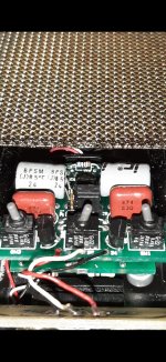
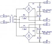
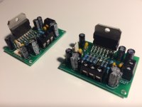
To monitor the dual power rails for my HP amp , I made a simple under and over
voltage detector , which switches off the power (and relay) , and gives an indication of what went wrong.
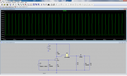
It works as it should , BUT I noticed when doing tests that it gets triggered by starting a fluorescent tube lighting or touching inputs just with a test lead.
Grounding the inputs without the 47k resistors or connecting the inputs with other
HCmos outputs , no problem , but the problem is now also on the optocoupler's
transistor side. When the opto transistor is off , again triggered by fluorescent tube
lighting starter.
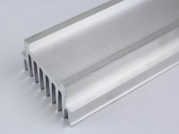
Will encasing it in an Aluminium casing solve this ?
Now I made lots of Cmos devices , never had this problem , but now I live in a
electrosmog environment , with lots of badly laid , overhead power wires and a
nearby WiFi transmitter. I had an computer mouse that always switched off when
starting the fluorescent tube lighting. Pulling the USB out and back in , restarted it.
Here are my options :
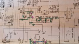
A RC filter after the HC132 to filter out the glitches. Effective , but I don't want a
big delay and if the C is too big , there is no room for a diode to protect the Hcmos
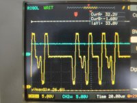
IC. (How big , or how long are glitches caused by fluorescent tube starting ?)
Or at the opto side = the HC 132's input . Again a cap , but not too big that it can
destroy the opto or the cmos input.
I can't go for lower resistors , because of battery power and it would change the
switching levels.
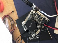
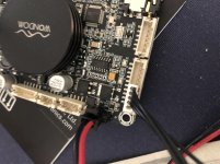
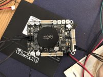
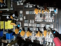
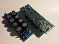
Yes I can experiment , but i've made a very small pcb with all smd's , which makes
it very difficult and big chance of the copper of the pcb coming loose when soldering too often and everything around it becoming too hot again.
So I ask here first , for people's experience with this.
Yes it is not strictly "Power supplies" , but is is to monitor de power supply to my
HP amp. That's why I posted it here. Thanks.