Suggestions for drivers to integrate into a TV shelf ?

So, I've got a TV sitting on an Ikea Kallax shelf (something similar to the attached image). I was thinking to fit a pair of speakers inside the outside squares. With some carpet and acoustic fabric, they could sit tightly in there.

Each cube's inside dimensions are 33*33*39cm. So about 25-30l of internal volume.

I've got a zoudio 4 channels dsp/amp I could use for this. I'm not aiming for the sky quality wise, just something better than the awful soundbar currently there.

I was thinking about a rather conventional two ways with a 6.5" midwoofer ? Something like monacor DT140 (20€) + SPH176 (40€), crossing at about 2K ?

So, with all that in mind, any advice/suggestions on how best to proceed or on other drivers ?

Attachments

  • 9634e7d8298a9a3d1eb5bebab6c6afb8.jpg
    9634e7d8298a9a3d1eb5bebab6c6afb8.jpg
    21.1 KB · Views: 179

amplifier output weak and distorted.

I`ve got 1969 Sansui 5000A tuner amplifier and it worked for a day. Then both channels became very weak and distorted, both at the same time. Sound became choppy and at full volume it`s just a distortion. I`d expect 1969 amplifier in need of recapping but both channels became like this at the same time make me think that problem lies in power supply since it`s shared by the both channels. Ideas?

Chinese Mono LM1875 Board

Hi, I am new to this forum and I would like to apologize in advance if I cross any lines while posting this. I got two of these mono LM1875 kits on ebay with the intention of making a stereo amplifier. I have attached images of the assembled kit along with the schematic and board layout. This kit is available from multiple sources for around $3 or less and I thought it would probably be popular on the forums. After doing multiple searches using the search feature and google I have found no information about it other than a couple youtube videos made by JohnAudioTech. He seemed to think the board is laid out well and uses properly rated components. He did mention possibly replacing the input capacitor though. What I want to know is if there is any more information on these kits and what components people would recommend replacing if any. I plan to use a known genuine LM1875 chip rather than the one from the kit and powering the two boards with a power supply board from chipamp and an antek AS-1218 - 100VA 18V TRANSFORMER. My apologies if this information is readily available and I'm making a duplicate thread.

Attachments

  • s-l500 (1).jpg
    s-l500 (1).jpg
    32.8 KB · Views: 1,452
  • s-l500.gif
    s-l500.gif
    66.4 KB · Views: 1,411
  • s-l500.jpg
    s-l500.jpg
    20.5 KB · Views: 1,726

Reducing gain on red mono TPA3116 board?

Hi,

I bought a couple of the Chinese red mono TPA3116 boards on eBay, that have balanced inputs. I have connected them to a professional line level source (+4dBu) and they have far too much gain.


I started investigating what the gain value was set to on the boards and have been a bit confused by the resistor values:

R1 = 01D = 100kΩ (SDZ to PVCC?)
R2 = 473 = 47kΩ (GVDD -> GAIN - aka R2 on data sheet)
R3 = 01D = 100kΩ (GAIN -> GND - aka R1 on data sheet)


These are valid combinations listed on the datasheet, and it doesn't seem to match any of them?

Code:
MODE     GAIN     R1 (to GND)   R2 (to GVDD)
Master   20 dB    5.6 kΩ        OPEN
Master   26 dB    20 kΩ         100 kΩ
Master   32 dB    39 kΩ         100 kΩ
Master   36 dB    47 kΩ         75 kΩ
Slave    20 dB    51 kΩ         51 kΩ
Slave    26 dB    75 kΩ         47 kΩ
Slave    32 dB    100 kΩ        39 kΩ
Slave    36 dB    100 kΩ        16 kΩ

Closest appears to be Slave / 32 dB. But I would presume that it wouldn't work at all in save mode without a master.


Am I reading these resistors wrong?
Or have they chosen weird values?
Does anyone else have one of these boards and changed the gain on them?

Apart from the high-gain, the board is working well and appears to be sensible.

Really not excited about replacing tiny SMD resistors! 🙁


Thanks!


njh.

Attachments

  • IMG_7939.jpg
    IMG_7939.jpg
    753.5 KB · Views: 298
  • IMG_3442.jpg
    IMG_3442.jpg
    674.9 KB · Views: 290
  • IMG_0724.jpg
    IMG_0724.jpg
    593.5 KB · Views: 271

American Audio V4000 in protect

Greetings gents,
I’m helping my buddy with his AA4000. Presently the amp when powered up, channel 2 comes out of protect after 3~5 seconds and passes clean audio. Channel 1 however remains in protect. I’ve tested the output transistors for shorts, none found, all small semiconductors tested ok, bias set the same as the right channel across the emitter resistors. There’s approx 9mv of DC at this point before the relay. Channel one passes clean audio up to the relay, the relay however is not engaging. I pulled the relay and checked, tested fine out the PCB. I then went back through the protection circuitry but didn’t find anything on the second pass. Transistors tested ok, replaced the caps.
I’m a bit more frequent on the car audio pages/amplifiers but I decided to give this a go.
Has anyone experienced this before, or can suggest anything I’m overlooking?

Attachments

Rewiring 6n2+6p1 SE pentode to triode?

I'm assembling a small Chinese integrated amp kit using 6n2 and single ended 6p1 tubes (with silicon bridge rectifier). The schematic included uses pentode operation but I've seen variants (unfortunately the discussions are all Chinese) which appear to use triode operation.

Could someone please point me to exactly what changes need to be made in the attached schematic for triode mode? Do I have to be concerned with bias? Can I remove the 18k feedback resistor?

Attachments

  • 6n2+6p1-schematic-orig.jpg
    6n2+6p1-schematic-orig.jpg
    528.7 KB · Views: 1,403

Digital Designs SS5

this is a 5 channel class d amp. The sub channel works fine. The front and rear channels each have their own driver card. As soon as I put either one of the cards in either spot the amp goes into protect so i don't think the issue is on the cards. Even without the irs2092s chips out it still happens. Any ideas?

Attachments

  • 20200922_113754.jpg
    20200922_113754.jpg
    1 MB · Views: 91
  • 20200922_113828.jpg
    20200922_113828.jpg
    1,001.3 KB · Views: 77
  • 20200922_113824.jpg
    20200922_113824.jpg
    1.1 MB · Views: 110

Fane Sovereign 12-250TC and a low power SET amp

I'm looking with a lot of interest to this driver, and heared it in a 12v reggaesoundsystem in a large (360L) ported box with a 300w class D amp sounding very good.

I was wondering, for my living room and with the 100-98dB/1W/1m (depending on the source) if this speaker could be used with a low power SE amp. I have a EL-84 3W SE amp here that i could use for it. In theory i should have enough headroom on the amp (i mostly listen at 70-85dB at home) for it. But will that be enough to move that heavy cone and get real subbass out of it? Does anybody have experience with it with a low power amp, prefereable a SE of a few watts?

A 360L ported box models very good with this driver (or at least the pusblished T/S parameters), flat till mid 30's and F10 at +/- 26Hz...

Wall of passive radiators?

Im just toying with a concept here.

I notice fairly large amounts of bass coming from some very small bluetooth speakers.

can this be upscaled for a much large woofer?
what are the limitations?

i understand several radiators can be used with one active driver.

could you for instance build a large box (wide and high but not very deep)
with say one active 12inch woofer in the center and surround it with as many 6inch passive radiators as you can fit around it on the front surface.
i understand you would need to adjust weights and find suitable drivers/ passives.

why?

i could spend money on a high quality active woofer, and then use many relatively cheaper passive radiators to make a high fidelity high spl woofer thats relatively small compared to a ported/horned equivalent.


is this conceptually viable and worth pursuing as an idea?

Strange master volume potentiometer problem

Hi people,

I have a guitar amp here that sounds awesome for two minutes after I put a new master volume potentiometer in. After the two minutes the sound gets dull and the potentiometer becomes intermittent when I push the shaft.

Since the amp has three 12ax7 halfs running straight into eachother, without attenuation between them, I think the potentiometer is simply overstressed.

Measuring the signal voltage at the master volume potentiometers input only gives me 31 volts though, which seems awfully low to me ( Is this because I am not using a true RMS multimeter and the signal is severely distorted?)

Anyway, what I would like to do is cut the voltage at the potentiometer in half, the amp is 100 watt and way too loud anyway.

Would a voltage divider before the master volume pot be the best option?
What would be good values for the resistors to keep the sound as unadulterated as possible? ( Thinking about for example Miller effect of the phase inverter)

Below is the unmodded schematic of this amp. All gain stages have cathode bypasses now and all attenuators have been taken out.

Thank you in advance for your time and attention.

Attachments

  • Marshall schematic preamp.JPG
    Marshall schematic preamp.JPG
    142.1 KB · Views: 199

Crown K series 8200uf 110v capacitor substitute or source

Hello all, I have several Crown K1 and K2 amps needing the 8200uf 110v capacitors in the output modules replaced. I am looking for a less expensive alternative than Crown factory parts. I see a 10,000uf 125v Chinese capacitor on ebay for about $9.00 but am very hesitant about performance and longevity. Does anyone have thoughts and maybe a good substitute? Thank you.

SVS SB12 SB 12 Plate Amp Modul - Schematic wanted

For the device under
SB12-NSD
– SVS

I need a schematic, because of the necessarily of enhancing the gain factor.
According the attached image of the plate amp there are follow PCB's:
1) input board (maybe summing amp, low pass crossover network and line buffer)
2) power amplifier board
3) main board (switch mode power supply)
Because the circuit boards are purchased parts from different far east manufacturers, SVS Sound doesn't have a detailed circuit diagram.
Who know the actually manufacturer of the input- and power amp board ?
Thank you for an advice.
This thread doesn't help:
SVS PB12 NSD driver substitute

Attachments

  • 15629565118583231584568879588915.jpg
    15629565118583231584568879588915.jpg
    440 KB · Views: 543
  • 57f3f90870bb13743ba66a8e.jpg
    57f3f90870bb13743ba66a8e.jpg
    209.7 KB · Views: 202

Aleph Amp Power Question

I noticed something a bit curious when looking over the manuals for the (later) Aleph amps.

The Aleph 1.2 and 5 have the 4 ohm output at 1.5 times the 8 ohm output. But the Aleph 2 and 3 have it at twice the 8 ohm output. (The Aleph 4 manual does not specify a 4 ohm output. And, familiarly, all of then do poorly below 4 ohms, though the 3 is the only one that seems to specify a 2 ohm output.)

Is there a reason for this? To what extent would one expect it to make a difference when driving 4 ohm speakers? This does matter to me since (a) I have Dynaudio Contour 60s, nominally a 4 ohm load, and (b) I am about to take possession of a pair of Aleph 1.2s whereas my current amps are Aleph 2s (or VTL MB-185s).

RJM 6DJ8 Phono

Hello,
I've been trying to decide on a phono stage project since March. I've looked into most of the projects here, and considered most of the available kits on the market.

I'm at the point now where I just want to build from a schematic; there are too many PCB projects and kits to choose from.

I have some JAN 6922's (that I'm guessing will work here), and this schematic looks to be about as basic as they come.

I did find this thread, and I don't think anyone ever made PCB's, or not. But, that's fine. Coming up with point-to-point a layout shouldn't be too difficult.

There's even a power supply to go with it.

I plan to go ahead and order some parts soon.

Attachments

  • p6dj8_cir.gif
    p6dj8_cir.gif
    16.1 KB · Views: 187
  • p6dj8_ps2.gif
    p6dj8_ps2.gif
    12.8 KB · Views: 221

Minimum distance behind Driver to rear cabinet wall

Hello,
Is there a rule of thumb minimum distance (ratio of cone size) between the front and rear cabinet walls please. I am a novice cabinet designer and have just about got a grip on most of the params and in's n out's of sealed and ported boxes. But in all my research i have not found any guideline for minimum practical distance behind the driver.

Just looking at the situation i have the gut feeling that a system with the rear wall 1mm behind the magnet might not perform as well as a system that has more space behind the driver.

Many thanks in advance

Dynaudio D-28 project 2-way

Anyone bored enough to help me redo my lame attempt of an Xover?
Concept:
Combine a pair of eight(ish) woofers (7.5 inches actually) from some old Fisher 2-Ways and some Dynaudios D-28 tweeters into a decent two-way project. I decided to save and use the Fisher woofers since the cones are made of a "foamed" metal of some sort and could yield interesting results. As for the tweeters I had a good old pair of Dynaudio D-28 available so...
why not.

Restraints:
- KISS keep It Simple
- First Order / SECOND ORDER might be better¿?
-Use what is already available. Compromise.

To make the story short, I have no experience and I must learn from the process. I replicated the original dimensions of the Fisher boxes to have some reference as for the original engineering (if any) since I don´t have spec sheets for the Fisher´s drivers or way to measure them and thus the project became so far a trial and error kind of thing.

I´m happy(ish) with the sound (being listening to them for some months now) but I know my progress with the xovers is a sum of uneducated guesses and lots of listening. Will be fun to see what improvements we get with a more formal approach.😀

The xover started with an online calculator selecting 1900Hz as start point using 1st order Solen Split that yielded a 7.4uF cap for tweeter and 0.65 mH inductor for the woofer. From that point on trial and error evolved to the attached imaged where I added a resistor in series to the original components. 😱

TBH it sounds good but I´m sure you guys can help me take this ship to a better place.

Please don´t toss me into the flames this is my first time with speaker guts really. I´m reading some stickys related and I´m learning as I type LOL.

Cheers from Mexico.

Rob.

Attachments

  • Captura3.JPG
    Captura3.JPG
    44.9 KB · Views: 596
  • IMG_20200408_202342.jpg
    IMG_20200408_202342.jpg
    393.9 KB · Views: 568
  • IMG_20200408_202547.jpg
    IMG_20200408_202547.jpg
    296.6 KB · Views: 523
  • IMG_20200408_202556.jpg
    IMG_20200408_202556.jpg
    415 KB · Views: 530
  • DYNAUDIO_D28.pdf
    DYNAUDIO_D28.pdf
    1.8 MB · Views: 283

Not an inductor?!

Hi all,
I've been harvesting components from dead electronics, building up a box of goodies for the time when I'll need something to build my first x-over, or a BSC circuit, or whatever.
Today, I pulled apart a busted Samsung digital amp.
It had a bunch of these things in it. I assumed they were ferrite-shielded inductors.
I put one on my DATS V3 box, to see if I could get the value for it, and it says it's not an inductor.

Ok...so what is it then?


EDIT: I considered that maybe it was just faulty, since a direct measurement with my DMM returns about 0.6ohms, so I test all of them. Every one reads about the same; right around 0.5-0.7ohms.

Now I'm really confused... are they all equally shorted, or ???

Attachments

  • induc_1.jpg
    induc_1.jpg
    185.4 KB · Views: 206
  • induc_2.jpg
    induc_2.jpg
    190.5 KB · Views: 204

SQ degrades with Minisharc passthrough

I am playing with a MiniSharc board as a benchmark for my own DSP processor.

When a run SPDIF from my server to the Minisharc with no processing and back out to SPDIF to my DAC I think I hear a subtle degradation in sound, especially in vocals. I will confirm with a blind test as I am doing the switching myself but assuming this result holds, why?

1. Could it be jitter introduced in the Minisharc?
2. Is it the ASRC step from Redbook to 48Khz?
3. Is it my DAC (Denafrips AresII) is not as good with 48khz?

Is it all of the above?
Is any of the above?
Is the answer knowable?

Thanks, jd

Markaudio Driver Selection for Full Array

I'm building a second iteration of my arrays that will only include 2 possible 4" drivers from Markaudio for a full 16 driver per side at 9 feet tall:
Alpair 7MS or
Pluvia 7HD

Each driver is in it's own sealed enclosure which is about .3cuft.
Each driver will be individually powered and have their own volume control.

Most array builders go cheap. That's not the intention here, price is not a consideration. I liked the sound and off axis response of the original Pluvia 7's but they are EOL, so I must choose from one of the 2 above.

FS: ICEpower 500A Mk2 modules

ICEpower 500A Mk2
500W General Purpose B&O ICEpower Amplifier

I have a handful of these left over from a project.

£40 each including shipping within the UK (a little extra for EU)

Here is a link to the manual:
https://icepower.dk/download/2411/

Note you'll need a PSU (not to be confused with ASPs, although I think you can run one off a 500ASP)

Attachments

  • IMG_20181217_165633.jpg
    IMG_20181217_165633.jpg
    525 KB · Views: 946
  • IMG_20181217_165651.jpg
    IMG_20181217_165651.jpg
    502.9 KB · Views: 1,353

Upgrading Pioneer Amp

So I've been semi-upgrading a pioneer SX-205. So far I've changed out all the 4558 op amps (ugh) and all the signal path capacitors with panasonic fc series ones. That's about it. Schematic here: http://diagramas.diagramasde.com/audio/PIONEER_SX205_SX255R.pdf

PSU caps are a no-go, size is impossible to find without downgrading the capacitance. Resistors would be a pain because when replacing the caps I found out the solder pads come off wayyyy to easily.

Any help is appreciated.

Line level impedance calculator and a few extras

Almost a year ago someone (googlyone) told me to do a little reading and look into this stuff, that most of it is basic calculations. I took it to heart. Googlyone was right. I needed to look into it and most of it was basic. I read and skimmed through 6 or 7 books but by far the best one was Practical Electronics for Inventors, Fourth Edition by Paul Scherz and Simon Monk. One thing led to another… diyer. I’m not an expert nor did I use any formulas that are not already published. Please, if I have any blindspots or missed the mark somewhere, like googlyone, let me know gently.

The calculator: At it’s basic use you can see the impedance load you are putting on your DAC / Preamp when connected to multiple power amps. On the more advanced end you can use it to size a voltage divider to balance the output of Amps with different specs. (input impedance, gain, SE or balanced)

Thanks googlyone for the nudge I needed.


Impedance Calculator — STUDIOPHON

Attachments

  • Impedance Calculator.jpg
    Impedance Calculator.jpg
    805.3 KB · Views: 202

USB to SHARC & ADAU Digital Signal Processors

Is the USB interface to SHARC and ADAU processors the same device?

I saw this SHARC processor that includes a USBi "for SHARC" and I don't know if that's marketing or if the SHARCs require a different interface.

Link to SHARC DSP

Also shown for ADAU1452

Link to ADAU1452 DSP

In contrast to this USBi for ADAU 1401

Link to ADAU1401

Or is it a case of backward compatibility for the SHARC USBi?

100+ Vintage/Obsolete 60's/70's & Newer Transistors.

I'm selling my stash of vintage etc transistors, no idea of total, estimated 100 + Most are NOS, some pulls, but most NOS. Some came from a hifi shop shut down in 1987, some from parts collected over 20's years. Please don't ask me to list them all.


I'm asking £100. Will post most anywhere, UK/EU prefered.


Drop me a PM if interested, Andy.

Attachments

  • DSC02898.JPG
    DSC02898.JPG
    161.8 KB · Views: 234
  • DSC02911.JPG
    DSC02911.JPG
    161.6 KB · Views: 227
  • DSC02899.JPG
    DSC02899.JPG
    162.6 KB · Views: 232
  • DSC02900.JPG
    DSC02900.JPG
    162.3 KB · Views: 259
  • DSC02901.JPG
    DSC02901.JPG
    162.4 KB · Views: 221
  • DSC02902.JPG
    DSC02902.JPG
    162.9 KB · Views: 121
  • DSC02906.JPG
    DSC02906.JPG
    160.6 KB · Views: 128
  • DSC02908.JPG
    DSC02908.JPG
    162.9 KB · Views: 107
  • DSC02910.JPG
    DSC02910.JPG
    162.8 KB · Views: 109
  • DSC02903.JPG
    DSC02903.JPG
    162.4 KB · Views: 133

Super Pensil 12 build

Received my drivers, did a "rough" layout of cabinet material needed and have 2 4x8 sheets of Baltic birch ordered.
To do:
Decide on what veneer
Binding posts
Outriggers
Stuffing.
This will be a far easier baffle then I am used to as there is only one driver.
Really looking forward to getting into this groove again as it has been a while.
Thanks to you guys for providing me the opportunity and the information to be able to do this.
:worship:

Attachments

  • drivers.jpg
    drivers.jpg
    219.7 KB · Views: 731

Sound of Aleph 2 vs Aleph 3

I have a factory Aleph 3 that I like very, very much.
I also have diy Aleph 2 monoblocks.
I recently noticed that the sound from the factory Aleph 3 is more relaxed than my diy Aleph 2's.

I am wondering if the differences I hear are due to differences in the design (of the Aleph 3 vs the Aleph 2) or due to the parts used (in the factory 3 vs my diy 2's).

It seems a good idea to first check if the difference is due to the design. Has anyone heard the FACTORY Aleph 3 as well as the FACTORY Aleph 2? Did the 3 sound more relaxed than the 2?

Did anyone who has ever built and modified an Aleph hear a difference with resect to perceived "relaxedness" of the sound when using other brands of circuit capacitors (not PSU capacitors) or 5W resistors? If so, what gave the most "relaxed" sound?

My 2's were built by a friend a long time ago and I do not know how well the mosfets were matched. What does an Aleph sound like if the Mosfets are not matched properly?

Please note I am not interested in ways to make a "better" Aleph 2. I like the sound of the factory Aleph 3 and am not interested in changing the first stage of my 2's using ZVP, Toshiba Jfet or other parts. I simply would like to know how relaxed an Aleph 2 can sound compared to the Aleph 3 that I like very, very much.

Thanks!

Putting a Faital Pro 15HP1060 in a superscoop designed for PD1850

As above. someone I know has a pair of unloaded superscoop cabinets going begging. I'm wondering whether the 15" faital driver would work in them (drivers I already have, but do appreciate I'd have to adapt the box to take a 15" instead of an 18"). I guess they perhaps wont go quite as low as the PD1850 but otherwise would there be any drawbacks?

Does 2 FR drivers nullify the point source advantage of a 1 FR driver speaker ?

I am building HT speakers with FR drivers for LCRS. For drivers I have narrowed down to the FaitalPRO 4FE35 30W, 8 ohms, 91dB. My AVR is rated 50W, THD 0.08%, 2channel driven @ 8 ohms.

These drivers are also available in 16 ohms. I was thinking of using two 16ohm drivers in parallel ( to get an impedance of 8 ohms ) for the LR speakers. I want to do this because when I listen to music in 2.1 configuration on the AVR I can use the maximum available 2 channel power/wattage of the AVR.

Question - Will doing this nullify the point source advantage of a single full range driver speaker because my fear is that the throw of the two closely places drivers on the speaker will interact acoustically and smear the stereo imaging for 2 channel stereo music ?

Can anyone help with my L-pad please, tweeter still too loud :(

Just bought an L-pad and it attenuates the sound but not quite as fine adjust as I would like. It maybe because I'm using a 8 ohm l-pad as its all I could find and a 4 ohm tweeter. I don't understand the electronics of it but the fine tuning isn't quite there. I have to set it to practically minimum just before it switches off for it to get near the level I want and even then its slightly too loud. Is there anything I can do to get the level to where I want it?

Eminence Beta 12CX/ASD1001 coaxial upgrade modification options?

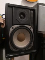
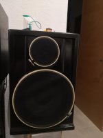
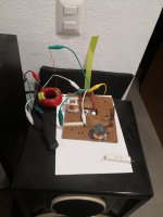
Long time ago I bought some Eminence coaxials and compression drivers including Beta 12CX/ASD1001 and Beta 10CX/APT50 combos. Since then I have been building various cabinets in ply and pine and trying to assemble crossovers for them until I last year decided to buy a pair of pre-assembled PXB2:2K5CX allegedly designed for these combos since my home made crossovers had serious issues and I got tired of having a unfinished project. Ive managed to put together one pair of monitors with 12CX/ASD1001 + PXB2:2K5CX which I am very happy with both the box and the sound. The Beta 10CX and APT50 are spares for future project, more about that later.

I am now curious to know if it is possible to improve the sound without drastic measures? The sound is large, warm, dynamic and for the most part just how I like it with a few exceptions. The midrange area around 2kHz is a bit muddy and uneven I am sure this is because A) the bass have ugly peaks around this area and should be crossed lower than 2,5kHz, and B) the HF driver doesn't really have much volume in this area and it is recommended to cut of at 2,5kHz, and possible C) some baffle resonance issues or other box problems.

Another problem is that the HF L-Pad in the crossover seems a bit too much given the higher sensitivity in the 12" compared to the 10" which I believe was the original aim for the crossover. Some of the highest frequencies seems at least a little bit missing but that may be the rolloff of the driver rather than the LPad.

I have read a lot of threads and see various options, changing crossover and HF drivers seems to be the most common solution and this is no problem for me as I want to use the ASD1001 and the PXB2:2K5CX on the 10" instead, and use the APT50 for another 3-way future project. Yes a lot of projects in my mind.

I have narroved it down to considering the following parts:
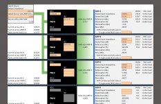
HF drivers:
Eminence PSD2002 106dB rec. xo. 1,2kHz
Eminence PSD2013 108dB rec. xo. 1,5kHz
JBL/Selenium D220Ti 109dB rec. xo.1,5kHz
PRV Audio D280Ti-S 109dB rec. xo.1,8kHz
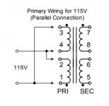
Crossover parts:
Eminence PXB2:1K6 1,6kHz LF12/HF18 no l-pad
Eminence PX-LPAD variable-10dB

Are there other options I should consider?

I see the new KP3012CX 12" coax have a much smoother rolloff so that may also be an option but I feel then its a fully new project new box much higher cost etc.

Did anyone else get a lot done during this damn pandemic?

Not shown: a jfet tester, and Singing Bush. (Too hot and humid this summer.)

All of this construction is due to that great solder from the Store, which makes soldering (and almost makes desoldering) a pleasure.

I hope the image is right-side up when you click on it. I don't really know how to work these computers. (It was so much easier in the slide-rule days.)

Attachments

  • IMG_0318.jpg
    IMG_0318.jpg
    554.6 KB · Views: 558

Peavey Transformer 212 Troubleshooting

Hi all,

I have a Peavey Transformer 212 with an odd issue. After power up, I hear this "whooshing" noise (sounds like a steam train). See video here for details. The only things that seems to affect the sound are the delay switch and pots.

I pulled out the control boards (very interesting PCB layout!) and noticed that the delay level pot (I guess it's an encoder) was wobbly. See video here for details. Other than that, there were no visible issues that I could see; the boards look brand new.

Checking the schematic (see attached), it looks like the encoder in question is an ENC2425V 16mm 24 pulse vertical encoder w/o detents. I haven't been able to find this part via a websearch, so I emailed Peavey about it.

Anything else I should try to troubleshoot? I'd like to confirm this encoder is bad before replacing, but probing the pins with a DMM didn't really tell me anything (readings were jumpy, but so were the other encoders I probed).

Attachments

Looking for SAE MK1B parts

Anyone have a SAE MK1B parts unit laying around? I am looking for an EQ board and an outer shell case. I am repairing one that has a bullet hole in the back. bought it this way. the main board and power supply survived, but the bullet hit the back of the chassis just below the speaker terminals and hit the back of the EQ board and destroyed 2 inductors and the backs of 2 slider pots.


Someone out there has a box of SAE parts laying around or a dead unit in bad shape that would be a good donor.


ZC

WTB amplifier suit xls10+ passive build

plate amp or other.
good sound quality a must.

for peerless XLS10 with passive radiator woofer, plenty of headroom required, for potential upgrade.


will be upgrading to stereo woofers eventually.
so dual channel options are good, or if you have two matching mono amps?


my absolute dream is the hypex FA502 (as this ticks all boxes plus more, but is maxing out my budget big time)

location Australia, and i can help with managing international shipping.

ND90 4Ωvs 8Ω for boombox

I cant choose between the two variants of the ND-90 for my boombox project.

I like the response of the 8ohm one much better than the 4 ohm one ( both are in a 4 liter box with a port tuned at 63hz). I know that this is just another sprite build, but given the fact that i am going to power them with a battery pack(21v 5s 70wh) -therefore i need that efficiency- I am concerned about the battery drain in conjunction with the baffle step circuit the sensitivity of both the drivers in going to drop really low (bsc for 4ohm is a 6ohm resistor parallel with 0.4mh inductor and a 8.2 mF cap, not sure why he uses a cap in a bsc/ 8ohm a 20ohm resistor with a 0.9mh inductor). The efficiency of the drivers drops a lot especially when placed in a box.

Which one would you choose for the bass the volume and the battery endurance?

p.s i am guessign the max wattage i would drive them would be like 5watts maybe 10 if i want to annoy everyone around.

Primare A30.2

Hello to fellow members,

I've been only reading for a while but it's my first time writing something. I really admire all your work thus come seeking for help.

I have a Primare A30.2 amp and was looking for a way to convert the voltage from 120V/60hz to 220V/60hz. I looked into the schematics but honestly have no idea how to read it. If it's a simple jumper tweaking, I thought I could do it myself so I was wondering if anyone could shed some light before I take it to a dealer and spend $$$.

Thanks.

John

Attachments

Hammond 229D56 Tranny

Today I applied power to this Hammond tranny. I was a bit surprised at what happened. To me, this looks like a typical dual winding primary and secondary tranny. Based on the diagram, you would think you can simple wire the 2-sets of primary terminals in parallel to get the resulting 28VAC on each secondary.

The 1st image shows the schematic with 2 separate and independent windings. To test it I wired pins 2 & 3 together and pins 1 & 4 together and then connected to 115VAC. Now, I know it's been over 50yrs since I had basic transformer theory (I was never in the industry though), but there must be a critical part of the theory I'm clearly missing, despite having successfully wired lots of trannies over the past 10yrs without issue in my DIY audio projects.

After, about 45secs I began to smell something 'off' and immediately pulled the plug. The primary side (without any load on secondary), was too hot to touch! I never got around to measuring the voltage on the secondary.

So, I pulled the Hammond datasheet for this particular tranny and found that their wiring diagram (2nd image below) was different then the way I had wired it. Still both in parallel though. I don't understand why, the way I wired it, caused the overheating, unless it was a phase related issue. Would someone be so kind to remind me of why this happened and the proper way to wire primaries in parallel. It seems clear to me the windings on this transformer are completely independent of each other, except for the core. Could the tranny be defective?

Attachments

  • 229D56 Schematic.jpg
    229D56 Schematic.jpg
    13.2 KB · Views: 91
  • Ham229D56_Diagram.jpg
    Ham229D56_Diagram.jpg
    17.1 KB · Views: 86

Digital Playback Front End choices?

I have a Topping D90 external DAC which accepts SPDIF, USB, I2S, & AES digital. The latter is what I have using my old cdp as a transport. However CDs only go so far.

Without breaking the bank, i'm looking from a dedicated non-PC / laptop based, stand alone 'digital front end' where I can plug a USB flash drive or it may have it's own internal hard drive. It should have a basic menu so I can scroll around the folders and choose what files to play.

Connectivity, it seems USB is most common but i'm not a big fan of USB and uncertain if it's reliable as I2S or other dedicated formats.

Also digital front end should support DSD SACD, FLAC, WAV, MP3, the usual etc.

I'm not having much luck searching online and it seems most units are comprehensive having builtin DAC, amplifier, etc. which I don't need. I suppose in this day of age, people rely on their hand held smartphones and do BT streaming but i'm old fashion. I want simple plug N play, direct access. 😕

Designing a sub around amplification | Can 220W get me to 20hz?

I'm wanting to build some dual subs for my system before the end of the year on as low of budget as I can manage given my needs, namely that I'd like between 110 and 115b of output at 20hz-90hz if possible, and that the dimensions not exceed 20in wide * 20in deep * 78.7in height.

I'm fully on board with using DSP to get there and smooth any troublesome peaks.

The design most appealing to me currently is the VBSS given a low cost of ~100 for drivers + 100 in materials per sub, however the inuke amplification required could potentially bring the cost up to 600USD... farther than I'd like to go if I can help it.

I currently have about 16 channels of 220W @ 8ohm amplification thanks to two ATI built Crestron CNAMPX-16X60s. Very clean, low distortion power. Given that I won't be most of those channels any time soon, I'm wondering if I could use that power to drive subs instead, and save money on having to buy yet more amplifiers?

I know some designs like tapped horns can get you more output for your watt... would that be a possible option? I know there would be some crazy peaks in the xover region, but I imagine those could be deal with via DSP. Dual voice coil driver could also be a way of getting more of my amplifier's power to the driver?

The Eminence 20Hz Tapped Horn – Volvotreter Homepage <- This horn seems like it'd check most of my boxes, but at 240cm it's slightly too tall (200 is more my limit), and the drivers listed are pricier than I'd prefer (would like to try and keep it to 100 per driver).

Currently trying to educate myself on hornresp but I've a lot of learning to do. In the mean time, any advice y'all have would be greatly appreciated!

FS Motronix Mosfet amplifier modules

I have many Motronix MRF-400H mosfet amplifiers (Approx 30pcs!) in stock (Barely used).
a few of them with Nichicon caps installed, all of them are in perfect working condition.

Price for matched pair: 30$ (BNIB on eBay 40$+15$ shipping for each!)
Worldwide shipping: 12$. (4 pairs or more, free shipping!)
Paypal fees on me 🙂


Specifications:
RMS continuous power:
150 Watts driven into a 4Ω load (tested with 2X40V DC Power Supply)
85 Watts driven into a 8Ω load (tested with 2X40V DC Power Supply)
0.03% Total Harmonic Distortion (THD+N)
Load: 4-8Ω (*** Can work with 2Ω load when use 2X30V DC Power supply)
Signal-to-Noise Ratio: >100dB A-weighted
Frequency Response: 20Hz to 20kHz ±0.5dB
Bandwidth: 20Hz to 100kHz ±3dB
Damping Factor: >200 @ 4Ω
Slew Rate: 30 Volts/ ms
IM Distortion: <0.05% (IHF)
Input Impedance: 20k ohm

Attachments

  • MRF-400H.jpeg
    MRF-400H.jpeg
    306.7 KB · Views: 333

Boards FS: MyRev RevC 1.3 Monoblocks and Older VSPS

Cleaning out my project bins and have the following unpopulated/bare boards for sale:

1. (2) MyRef RevC monoblock boards. These are the v1.3 boards that I ordered from Siva (linuxguru). See the pics in the following post: https://www.diyaudio.com/forums/chip-amps/167458-myrefc-build-guide-post2844341.html. I will include copies of the schematic and board layout that I received with the kit. $15+shipping for the pair.

2. An early (2008) VSPS (Very Simple Phono Stage) board from RJM. See the following thread for more info: https://www.diyaudio.com/forums/analogue-source/33555-diy-phono-preamp-cheap-simple.html. I will include a copy of the original BOM. $5+shipping.

PM me if you have questions. Thanks!

-bill

Rca rs188

This is my first working tube amp. I pulled it from a old readers digest portable record player. I built a dim bulb tester and recapped it before hooking it up to my pioneer bs22 speakers. Wow am i impressed!!
Anyway...now what? Id love to remove the tone controls. And maybe improve the circuit somehow. But, i also want to keep it simple...
Thanks in advance

Yamaha YPA-600

Amp powers up but no output .

I was checking for regulated voltages and on 1 opamp I bet the following voltages

NJM4556

Pin 1:21.35
Pin 2:12.79
Pin 3:12.79
Pin 4:12.62
Pin 5:0.02
Pin 6:12.64
Pin 7:12.78
Pin 8:12.78
Pin 9:21.53

Is this normal for these amps?

Attachments

  • 0126230A-D92D-4C19-9E66-7D777AAD3973.jpg
    0126230A-D92D-4C19-9E66-7D777AAD3973.jpg
    1 MB · Views: 153
  • 73BC2DB0-C2D9-4DF1-9DA6-2AF5C095060A.jpg
    73BC2DB0-C2D9-4DF1-9DA6-2AF5C095060A.jpg
    1 MB · Views: 139
  • 35EC9D66-8857-48F3-8AC9-FCC96CF73CDD.jpg
    35EC9D66-8857-48F3-8AC9-FCC96CF73CDD.jpg
    990.8 KB · Views: 138
  • E2EEB0DB-ED8C-4A71-A0F8-D4FE107C665B.jpg
    E2EEB0DB-ED8C-4A71-A0F8-D4FE107C665B.jpg
    1,000.2 KB · Views: 172
  • 3A31D643-7050-499D-870A-9A6696B16BAF.jpg
    3A31D643-7050-499D-870A-9A6696B16BAF.jpg
    930.5 KB · Views: 121
  • C69CCBA2-5237-41AB-BBB2-DBA670F0BDFD.jpg
    C69CCBA2-5237-41AB-BBB2-DBA670F0BDFD.jpg
    998.8 KB · Views: 129

Zebra Wood Frame Around My AT-LP120XUSB

While rummaging through my wood pile, I ran into some zebra wood scraps that I thought might look cool around my AT-LP120XUSB. Spruces it up a bit. 🙂

For now they're just tacked in place on three sides with some hot glue. I plan to dampen the underside of the plinth with Plasticine sometime....when I do that I'll trim them up and fit them a little better, and re-fasten them a bit more securely, tho I'm not sure I want to mount them permanently yet.

000_3969.JPG

000_3968.JPG

000_3971.JPG

000_3593.JPG

Hafler DH220 - Upgrade kit gone wrong?

As stated I purchased the ebay kit as seen on them here and there with the new PC boards and the like. So, Have only recapped the Hafler DH110 with success I then though to take this on. Long story short. I felt pretty good about my soldering job on it with no cold solders that I am aware of. It power on with a variac and have it up to 110. No fuses blown. Great. Get speakers on it and nothing. Not even fuzz sound. Wiggle the rca's and no sounds as well as speaker wires to hear that cracking sound when you hook them up. Just nothing. So, not knowing how to back track diag. Could someone walk my through what to check first and then the next to see what I hooked up wrong. Was working on old board and wires before.

Just to have full info.. I also rewired the entire amp as well and thought I followed the instructions to the letter.

Can get pics up if needed. Thank you for any help to this noob trying to be a one of this idiots to take these things on.

I do have a Fluke Multimeter if I could also know what setting to be on to check different parts of the amp out to diag my issue.

Geez, what a noob...

NI LabVIEW now FREE for personal, non-commercial use

National Instrument has made a "community edition" of LabVIEW 2020 available for free. You need to create an account (of course) and redo the license after a year; it's a fully functional "test and measurement" program development environment that works with GPIB, Serial and other USB connected hardware. Pretty good.

Regarding Audio test, there's not much you'll be able to do with it that hasnt been thought of and done already - considering the myriad of available audio test programs available in the last 20 years...

What you can do with it is create something specific to a particular need, that other general test system programmers wouldnt have possibly thought of -

Something like "When I clap my hands, give me a spectrum analysis of the sound I'm measuring in the moment just before the clap".

I'd be interested if anyone here installs and uses the LabVIEW "community edition" for audio test and measurement -

Looking for crossover for Satori 3 Way build

Hello. I Thought in a project at the begining of this year with SB Acoustic drivers. I wanted a 3 way floorstander with the following config:

Tweeter: SB29SDAC-C000-4
Midrange: SATORI MW16P-8
Woofer: SATORI WO24P-8

I thought in a active system although I have changed my mind and would go for passive... or selling the drivers because I do not have much time not space for this nice project.

Does any one of you has any suitable crossover suggestion for this config?

Thank you

Solid state relay for 3000W subwoofer amp

I have a Behringer nu6000dsp that gives a hellacious power-off thump when switched off by my smart power strip.

I want to use a relay at the speaker outputs that will open before the power is removed, which I can achieve with the delayed output on a surge protector I have.

I've perused many threads on relays and it sounds like mechanical ones are problematic because I'll never be switching with a load to keep the contacts cleans.

The possible issue with a SS relay is linearity at low levels.

I'm thinking it's probably not an issue with subwoofer frequencies but wanted to check with the more knowledgeable.

Would this one be suitable?

Solid State Relay 25A | RSS Solid State | Solid State Relays | Relays & Timers | USA

Key Features
Current ratings up to 90A at 660VAC
AC (90-280V) or DC (4-32V) input
Input current regulated 10mA
Photo isolation of input and output (up to 4000V)
Zero voltage turn on
Dual SCR output with built-in snubber
Optional fingersafe cover
Worldwide approvals: UL
C-UL
TUV
CE
LED status indicator standard
Updated pressure plate for easier installation of wires
New housing design keeps wires from twisting and breaking
Dual SCR output with epoxy free design

Can anyone identify or confirm this is a 30v zener diode ?

I bought these supposedly 30v zener diodes.could anyone confirm that they are as such?Never saw such notation.


PS.They are indeed...just measured them, but i couldn't find a 40v supply at hand before writing this topic..As i can't delete it anymore...

Attachments

  • 20200920_141248.jpg
    20200920_141248.jpg
    1,003.3 KB · Views: 143
  • 20200920_141306.jpg
    20200920_141306.jpg
    698.6 KB · Views: 148
Projects by fanatics, for fanatics
Get answers and advice for everyone wanting to learn the art of audio.
Join the Community
507,827
Members
7,889,917
Messages

Filter

Forum Statistics

Threads
406,326
Messages
7,889,917
Members
507,827
Latest member
Sus12