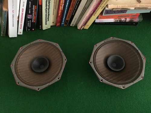
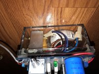
My water-flosser died yesterday, and of course I couldn't dump it without attempting to fix it.
It responded to the controls, at least with the LEDs, but the main motor wouldn't run.
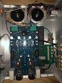
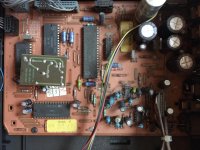
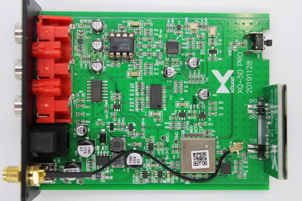
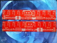
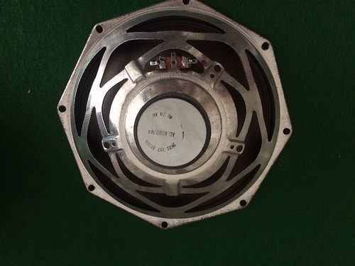
The motor is controlled by two paralleled MOSFETs (SMT code A27K, thus should be AO3402).
They act as PWM controllers and power switch (the motor/MOSFETs are directly connected to the Li cell).
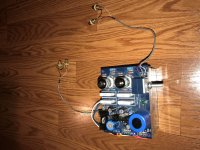
Shorting D-S made the motor run, and when in the ON state, a PWM waveform was present on the gate, but the amplitude was ~1Vbe, too small to turn the FETs on.
Upstream of a 330R gate stopper, the signal had a normal amplitude, ~full battery voltage.
I immediately suspected that one of the gates was damaged, and had a parasitic junction behaviour.
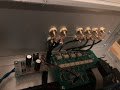
To ascertain that hypothesis, I connected a component tester in low-voltage, high-current mode between the G and D, and this made the motor run immediately.
The tester only showed a linear resistance between the terminals, probably the 330R and subsequent logic output in a low state.
When I attempted to start the flosser normally, with the control button, it turned on as it should: connecting the tester cleared the defect in some way.
Apparently, there was something like a parasitic SCR behaviour active, and since the power was always on (via the drain), it couldn't clear by itself.
Connecting the component tester forced a negative/positive gate excursion of several volts, and unlatched whatever parasitic device was present.
Not a completely outlandish behaviour for some ESD protection junctions, but the mystery is why an unprotected device, as the AO3402 is supposed to be, shows such a weird behaviour?


