Sub Heatsink for 6 Zener Diodes in DO5 Outline for electric isolated Mounting

I am looking for a possibility of isolated mounting of 6 pcs DO-5 zener diodes one the same heat sink.
The diodes looks like this versions:
1N3309B Z- DIODE 10V 50W DO-5 | Capcomp Shop
NTE Elektronik nte5247ak Zener Diode - 6.8v 50w do-5 5% Cathode Case | eBay
Actually there should be heat sinks for it with one surface accordingly TO247 and one surface with a hole of 5mm Ø

The reason for that is the follow:
In a preamp with shunt regulated power supply there must replace high power zener diodes in an electrical isolated outline like that one from this rectifier:
KBPC3510FP pdf, KBPC3510FP description, KBPC3510FP datasheets, KBPC3510FP view ::: ALLDATASHEET :::
go to the first attachment.

The replacement parts of this zeners are only available in an electrical unisolated DO-5 outline, but I want to fix five or six of this electrical unisolated devices of this zeners on the same heatsink (the last image shows only a temporary solution, which I don't like).

Thanks for an advice.

Attachments

  • DSCF5143.jpg
    DSCF5143.jpg
    913.7 KB · Views: 195
  • DSCF6763.jpg
    DSCF6763.jpg
    5.1 KB · Views: 166
  • DSCF6765.jpg
    DSCF6765.jpg
    7 KB · Views: 174

Help needed for unknown SEMELAB Power Zeners "8136 8215E"

I want to know a replacement for the above mentioned zener diodes. I don't know the naming of the associated outline, but it looks similar to those under
VS-GBPC2508W | Vishay VS-GBPC2508W, Bridge Rectifier, 25A 800V, 4-Pin GBPC-W | RS Components
but with only two connectors.
The power zeners (7 pcs) are in use in a voltage regulator for creating the anode voltage of a diy tube pre-amplifier with ECL-86
Thanks for posting a URL for a data sheet.

DIY Line array - Matching AMP power with the RAW speaker

Good morning,

I'm looking to design and build some DIY line array active speakers for small live use (200-300 peoples, indoor).

I think starting with 10 inch raw speakers, and to put two of them on each cabinet, with one compression driver.

But my problem is all raw speakers in my country doesn't have a precise documentation (mostly china stuffs), so I don't know its effective RMS power, effective frequency range, ...

How can I proceed to evaluate the best amplifier circuit power I can use to achieve my need? As we will use it mainly for rock/prog metal, I wish to achieve the maximum quality.

Thanks in advance.

Tian Stability Plot at multiple points across the Output Swing

OK, I think I've made this work. Multiple Tian stability plots across the signal swing. Thanks to jcx and fas42 for assistance.

I have a 250W CFP output stage I'm working on. I wanted to break the CFP local loop to check GM & PM at several points on the output swing, from -80V to +80V. Here's what I did.

Nested .step sweeps:
.param dcin=0 prb=0
.ac dec 100 1 1e9
.step param prb list -1 1 ; Tian loopbreak probe V1 and I1; set prb=0 to turn off probe
.step param dcin list -78 -40 0 40 78 ; run Tian loopbreak at each of these voltages

One .func in the plot.defs file for each of the dcin values:
.func stb1() -1/(1-1/(2*(I(VI)@1*V(OUT)@2-V(OUT)@1*I(VI)@2)+V(OUT)@1+I(VI)@2))

.func stb2() -1/(1-1/(2*(I(VI)@3*V(OUT)@4-V(OUT)@3*I(VI)@4)+V(OUT)@3+I(VI)@4))

.func stb3() -1/(1-1/(2*(I(VI)@5*V(OUT)@6-V(OUT)@5*I(VI)@6)+V(OUT)@5+I(VI)@6))

.func stb4() -1/(1-1/(2*(I(VI)@7*V(OUT)@8-V(OUT)@7*I(VI)@8)+V(OUT)@7+I(VI)@8))

.func stb5() -1/(1-1/(2*(I(VI)@9*V(OUT)@10-V(OUT)@9*I(VI)@10)+V(OUT)@9+I(VI)@10))

I think I'll start a thread on this, so others can see it, cause it's useful.
Here's the schematic and plots for your viewing pleasure:

Attachments

  • OutputStage.png
    OutputStage.png
    25 KB · Views: 157
  • Screen Shot 2015-03-31 at 3.09.40 AM.png
    Screen Shot 2015-03-31 at 3.09.40 AM.png
    364.6 KB · Views: 146

Perfecting loudspeaker design using novel polymer materials

Hello!

New forum member here who is in the process of building my first loudspeaker pair, separate thread regarding the build found here: Studio 3-way reference monitor build, need help choosing drivers

I have been reading a lot on the subject in recent weeks/months and I have been sharing this new found interest with my brother who has responded in kind and now we are 2 really interested persons who would like to really get serious when it comes to loudspeaker design. I am currently studying to become a medical doctor, which is not really applicable to loudspeaker design (if you're not counting human hearing, maybe there is a future for me in studying and advancing our knowledge of human perception of sound?? Any input/thoughts/available paths forward regarding this would be greatly appreciated).

My brother has finished his phd in chemical engineering/material design. His graduating work (not sure what you call this in english speaking countries? Graduate work/project?) was concerned with synthetisizing novel polymers based on a set of wanted characteristics.

We have now developed a vision of using his knowledge/skill to develop new materials for loudspeaker drivers and loudspeaker enclosures, materials tailor-made to the needs of the frequency range in which the driver/enclosure operates.

Imagine a midrange driver that utilizes a tailor-made membrane-material for its specific frequency range which results in perfectly matched characteristics resulting in frequency response linearity and extremely low levels of distortion. Then imagine using this same material for the enclosure for this driver. Then imagine using this same methodology for all drivers in the design of a complete/full range loudspeaker. Maybe there is a possibility of creating something great sounding and economical?? I can specify what (modern) techniques of polymer synthetization we are planning on utilizing if there is an interest in knowing more about the potential of polymer materials.

I would be extremely grateful for all input/ideas/information pertaining to our quest. What is the function of the membrane of a loudspeaker? What is the source of its inherent structural instability (break-up etc.)? How is this instability related to the self-oscillating frequency? How is this related to the molecular make-up of the material? What would be the ideal material characteristics of a membrane for a specific frequency range of a loudspeaker driver?

Any sources (books, links) will be gladly accepted and researched, any insight/input/ideas regarding the topic is extremely welcome!

What would be the ideal loudspeaker membrane/enclosure material? Discuss

audison av12

I have an audison AV12 in a very small, 18l vs 20 reccomended.


heres the TS parameters i pulled w dATS


Re 3.66
fs 39.4
vas 93.09
Qes .74
Qms 3.55
Qts .61
Le 1.47
EBP is 57


Im running about 220w into it in the box and its fat below 100hz to 20 hz in my honda Accord


Thinking of trying it in IB sice according to hornresp i would gain about 13db on the same power and still have excursion to spare.


Can anyone recomend something else? space available is 32"w x 15"h x 16"d gross


Priority is low frequency extension so i dont mind a large box since hoffman says so!


I built the little shoebox so icould get more tha the 6x9s in the rear deck.

Silent fan replacement in ART SLA-1

I have an ART SLA-1 (stereo class AB power amp) and the stock fan is noisy. I want to replace it. I'm not an engineer, but have replaced many noisy fans in computers. Apparently it is a 12v 40mm x 20 mm fan. Should this one work?

Silenx

Here is the original.

Thoughts??

P.S. I just took out the original fan; it's made by Bi-Sonic, and is a DC brushless fan, model SP402012H, operating voltage 12V (10.2 - 13.8), current draw 0.16A; power consumption 1.92w. The Silenx specs are: operating voltage 8-14v; current draw 0.03A; power consumption 0.36w, so that all seems fine. What concerns me is the Bi-Sonic is 7000 RPM with a Flow CFM of 8.53, and the Silenx is 3000RPM with a Flow CFM of 6. I don't drive this amp hard at all, so I don't expect it to ever get that hot; will this "quiet" fan be strong enough??

BBC style thin wall enclosure - how thin can one go?

I am about to order plywood for my speaker project, a subwoofer assisted two way speaker, with BBC-style thin wall enclosure. When researching the subject I found that as far as panel thickness goes Harbeth/Spendor/Rogers (so BBC contractors) used from 8mm in two way monitors to 12 mm plywood for larger boxes.

Now, from my local supply I can order only 7 mm plywood, even though its just 1 mm thinner than BBC spec, its as much as 12,5% difference from 8 mm panels used in commercial designs. So how thin can I go? I know that reducing panel thickness will lower the resonance frequency of the panel, which is a good thing according to BBC's approach, but there has to be some limitation, otherwise people would be using 3-5 mm panels to push the resonance below speaker's passband, which I haven't really seen in forums.

My two way design will cross over to sub, with Satori MW13P-8 in a bass reflex alignment tuned to around 70 Hz. Given relatively high tuning for this driver and some 5-5,5l net internal volume, simulations showed that I can use 2nd order BW highpass at some 130 Hz to land at -6 db at 80-85 Hz, where sub will take over.

It would a be a floorstanding design simply because my wife doesn't approve speaker stands. It will be 108 cm tall by 22 cm wide by 13 cm deep, but speakers will only use top 33 cm, so this subenclosure will also act as bracing at around 1/3 panel height. I plan to use 8 mm of alubutyl (2x 4 mm Silent Coat mat equivalent) damping on the inside to lower the amplitude of panel resonances. Front and back baffles would be mounted by screws, along BBC's design principles.

Your input would be much appreciated as I wanted to have panels cut this week to work on them during Christmas brake 🙂

impedance question

here is one impedance question

Suppose we have one amplifier class AB that is specified to 200w @ 8R
suppose that we load this amplifier with a load that is 64 R ( 8 units of 8R in series )
wiring will be very short
units are relatively small and equal so theoretically 200w of power will be equally distributed to the nod and each unit will handle 1/8 of the power .

So electrically that sounds ok
Question is what will happen soundwise and this type of load effect in the performance of the amplifier
--Will slew rate change ?
--Will damping factor change
--Will frequency response change ?
--Is there a chance that amplifier will oscillate due to load is out of specs ?
--is there anything else that might go wrong with such an arrangement ?

kindest regards
Sakis

Cheap solid state relays

I knew these knock off solid state relays were under rated current wise but the common 40 amp models have a triac inside rated for only 16 amps!

It lasted a few years doing intermittent duty in my coffee roaster before shorting closed. There doesn't seem to be a middle of the road price point on these. Legit models are like $40 and fakes are $6.

Attachments

  • IMG_1661.jpg
    IMG_1661.jpg
    925.3 KB · Views: 84

Am I doing this right? Tuning gains on mono amp for bass

Looking for understanding and making sure I'm doing this correctly. I've got a Pioneer GM-D9601 and 2 Pioneer TS-SW3002S4 Bass speakers, that I took out of my truck before selling it to a dealership. I will be hooking them up to my pc at home and powering it with an extra atx 500w power supply I had laying around. The speakers are 400w nominal power and nominal impedance is 4 ohms each. The speakers are in a closed box so I cant see how they are connected, but I believe they are connected in parallels because I get a 2 ohm reading when using my voltmeter on the two speaker wires coming out of the box, is this correct in how I figured this? and does this mean I treat it like 1 800w 2 ohm speaker? Or do I treat it like 1 400w 2 ohm speaker?

According to the amp manual the amp can output 800w at 2 ohms.

So following the formula I multiplied 800x2=1600
then the square root of 1600=40v, is this right?

Next, with speaker wire disconnected I will be rotating the gain dial clockwise until my voltmeter reads 40v. Is this right?

I will be testing with a 50Hz 0dB audio file from my computer and routing a rca cable from the 3.5 speaker out jack on the pc to the rca in on the mentioned amplifier. Let me know if there is a reason I shouldn't do this.

Also, I wasn't sure if I will need it, as I'm not sure how the amp will respond to the signal coming from the pc. But I have a LC2i that came out of the truck as well. Would it be better to put this in between the pc and the mono amp?

Thanks for anyone's help on this. Would hate to blow anything up. this bass sounded amazing in the truck, just want to put these to use until I have a vehicle to put them in (wont fit in the car).

FS: tribute choke, E182cc quad, Siemens sikorel 10000uf, jupiter vt caps and more

IMG-0255 — ImgBB
IMG-0256 — ImgBB
IMG-0257 — ImgBB
IMG-0258 — ImgBB
IMG-0259 — ImgBB
https://ibb.co/q1pJchY
https://ibb.co/mFV2nxj
https://ibb.co/vVc6P29
https://ibb.co/gjfj29K
https://ibb.co/hd049HZ

for sale:
quad philips e182cc
tribute 20h potted CHOKE
jupiter VT 15uf 100v capcitors
quad of NOS Sylvania 6b4g tubes
6szt Siemens Sikorel 10000uf 63v
10 pairs of Elna Silmic ARS 100uf /50v capacitor (good on cathode)


make me an offer, 20-30% less than ebay prices.
I want to get rid of it quickly.
I live in EU

Software to design amplifier circuit

Good morning,

I'm looking to design an amplifier with some digital based filters stuffs like driving TDA7317 EQ with Arduino Nano.

I usually run with Proteus to design & simulate electronic stuffs, but Proteus seems to not have a lot of audio stuffs. For example, I don't have TDA7294 chips for amplifying, TDA7317 for EQ, LC75281 for parametric EQ, ...

Is there any good software to design amplifiers / digital filters / ... other than Proteus, or is there any Proteus library to import most common audio chips in simulation?

Thanks in advance.

Recommend a 6" long throw driver

I am planning to build an open baffle "subwoofer" to complement my existing electrostatic speakers. The goal is to cover 30Hz to 100 Hz. Sensitivity can be as low as 86dB/1m. Each unit could have four drivers (space limit, one driver could be 6" diameter at most, they will be in line).
That means fs should be around 30Hz and Qts should be 0.7 to 1.2 or so. I think long throw is the most important requirement for an open baffle subwoofer.
What products shall I consider? (EU source preferred). Could any car audio drivers usable for the purpose?

Low pass cut-off advice for the SB26NBACS45-8

Hi,


WHat would ou advice as an electrical low pass cut-off for this driver, please ?


Mine is the NBAC but the NAC is similar. The H5 between around 1k and 2 k hz is worying me. My Due to the mid I wanted a 550 to 700 hz LP 6DB electrical, but I surmise the slope not to be stiff enough ? LR12 electrical instead perhaps, where according to you ?


Many thanks for your "poll" 🙂


The distortion measurment is from HifiCompass, I attached the 5.2V capture.
The filter will be passive with a zobel to flat the impedance.

Attachments

  • sb23nacs45-8_20mm_5v6hd.png
    sb23nacs45-8_20mm_5v6hd.png
    134.3 KB · Views: 139

Shigaclone mk2 black for sale

Hello

For sale is a shigaclone mk2 black high grade version.. it has tentlabs xo, zfoil output resistors, tibis regulator on v3 and v4. This board was assembled by tibi. It will come with the sanyo sfp101 that was modified by tibi. Will come with 8v power supply and transformer, aluminum puck, and remote. The remote control is a little beat up but works..

You will need 5v power supply for v1 and v2. You will also need a capacitor for the c8 position (.1 uf brown cap in the pic is not included)

Asking $250.00 .. this has not been used for about 2 yrs since i started streaming.

Buyer pays shipping and PayPal fees

Thanks

Attachments

  • B889A9AD-E2F1-4299-9B77-C6D6B4CF8660.jpg
    B889A9AD-E2F1-4299-9B77-C6D6B4CF8660.jpg
    986.9 KB · Views: 330
  • C663AF50-0312-41CD-BBE2-16A6519930C0.jpg
    C663AF50-0312-41CD-BBE2-16A6519930C0.jpg
    969.8 KB · Views: 328
  • 7F757CEE-1B1E-4FE4-B183-F01722E7E7B8.jpg
    7F757CEE-1B1E-4FE4-B183-F01722E7E7B8.jpg
    904.1 KB · Views: 301
  • DE398658-BE1E-4CF1-912B-D905337BDE71.jpg
    DE398658-BE1E-4CF1-912B-D905337BDE71.jpg
    996.1 KB · Views: 314
  • 190A31B9-1763-4C4C-96E0-5B40C8F5E05E.jpg
    190A31B9-1763-4C4C-96E0-5B40C8F5E05E.jpg
    1,001.9 KB · Views: 289
  • A69D93FC-8DAB-477B-9AEA-0A50F9EE4F18.jpg
    A69D93FC-8DAB-477B-9AEA-0A50F9EE4F18.jpg
    995.3 KB · Views: 128
  • 729B9558-C25F-4A11-97BF-77E4D98E49F7.jpg
    729B9558-C25F-4A11-97BF-77E4D98E49F7.jpg
    988.6 KB · Views: 133

Leaving voltage on the plate with a cold tube...

Wears the tube out prematurely.

I had read about plate voltage leading to stripping/poisoning of the cathode only applying to voltages higher than about 600V. Not the case with my phono stage. All tubes had 280V on them without heat. After about 6 months, the tubes were "worn out". Where I expected 2 or 3 volts (cathode resistor), I got only 0.8V.

Maybe there is something to keeping HV off the tubes unless they are hot or warming after all.

JBL LSR4300

Hi Gents and possible Ladies?

Have a desire to try reprogramming the firmware on my JBL LSR 4300 speakers. The digital pcb display at a quick glance receiver and A-D-A converter capable of 24/192 PCM, but somehow, and I guess it is in the software controlling the speaker, there are limitations to 24/96 PCM.

Is there anyone here in this huge community of knowhow, who actually know how it all fits together, or even know how to "cure" this on purpose limited performance.

I tried the JBL expert support. They told me this software is JBL intellectual property. I agreed on property, but made my reservations clear for the other statement.

I am electro-engineer for high power distribution networks (MW and TW), so my insights in this micro-world is nothing worth mentioning. Any help is highly appreciated.

Thanks in advance!

Stefan from Sweden

Tone arm replacement?

I bought a used turntable off ebay and when I got it there was damage to it. I got refunded almost all of my money with the offer to keep the table for $20.00 so I took the offer thinking I might find a different tone arm for it.

If there somewhere a person can pick up a tonearm at a reasonable price? It there a correct distance from the center of the platter it needs to be installed? I guess a site where I can find all the info I need?

It has a really nice direct drive platter but a cheap tonearm.

So, where can one buy loudspeaker drivers these days?

I haven't had to buy drivers in a long time. I see a bunch of stuff at Parts Express, and I see Madisound is still around. Speaker City seems out of business and Zalytron shows almost nothing.

I'm looking for a 12" woofer which will bass-ically 😉 run open baffle in a wall with an understairs closet behind. Ideally the woofer would have a top end die-off to cross over to a horn.* No sweet spot listening, more like whole-house sound, an EQ may well gently massage the sound. Not wanting to spend hundreds but the cheapies at Parts Express don't look too damped.

A grille to cover all this is also needed, perforated metal pre-made, I'm not making wooden frames for grill cloth.

*No I haven't decided which. I really want to use the Dayton 10" waveguide just cuz it's so cheap and cool but don't know what driver or tweeter I would mount to that.

LT3751 Driven, +/-400V Shunt Regulated Supply

I am not a tube guy. So I do not have a high voltage lab supply lying around on the bench. Only a pair with max. 30V 5A. But recently I want to experiment with a solid state amp for electrostatic headphones. So I thought a lab supply capable of +/- 400V 60mA, regulated, and with adjustable current limit would be handy.

To reduce costs, I want to use my low voltage supplies I already have, and use a switcher to convert it to the required high voltage, low current. After quite a bit of searching on the net, the not-so-obvious LT3751 actually fits the requirements best. The standard circuit on the datasheet is supposed to be capable of 500V 170mA. And all the components, including the transformer, is readily available. Apart from my specific application, I thought this might also be rather useful for tube fanatics not willing to compromise on their choice of Car Hi-Fi gear.

The schematics attached are as built successfully. They largely follow those on pages 26 & 34 of the datasheet. The negative version is not listed on the datasheet. It requires reversing the primary of the transformer, as well as the usual polarity changes after the secondary. Because the built-in “regulator” only accepts positive voltage, the output feedback voltage has to be inverted by an additional inverter using a LT1006.

I had quite a bit of trouble getting the converter to start without triggering the voltage limits which then turned the converter off. It could of course be due to the high current draw at start-up, and the current limit of the upstream lab supply. In the end, after a lot of trial and error, I managed to get a stable set up by using a 1k-4.7µF de-bounce at the charge pin. It also helped to lower the supply voltage to 22V. And I also found the inclusion of C6 (10nF) necessary.

To allow a coarse selection of output voltage, the feedback series resistor is split into 8x 49.9k. This, together with a 6-pole rotary switch, gives 6 output voltage steps between 170V and 420V.


Patrick

.

Attachments

  • 170209 LT3751 PSU 1.JPG
    170209 LT3751 PSU 1.JPG
    332.7 KB · Views: 673
  • 170209 LT3751 PSU 5.JPG
    170209 LT3751 PSU 5.JPG
    238.7 KB · Views: 615
  • 170209 LT3751 PSU 6.JPG
    170209 LT3751 PSU 6.JPG
    298.2 KB · Views: 587
  • 170209 LT3751 PSU 7.JPG
    170209 LT3751 PSU 7.JPG
    356.5 KB · Views: 582
  • LT3751 Regulator +420V Sch.asc
    LT3751 Regulator +420V Sch.asc
    6.8 KB · Views: 246
  • LT3751 Regulator -420V Sch.asc
    LT3751 Regulator -420V Sch.asc
    7.3 KB · Views: 230

Denon DCT-R1 No Audio No CD Eject

I got this Denon DCT-R1 for around $250 in hope I could repair it. It has audio signal out of the RCAs, but not out of the high level output. It has a HA13150A for the "amp" and it appears to me that pin 2 is grounded (or not getting its 3.5+ volts) and is in standby mode.

I have traced Pin 2 as best I can. It goes (from the amp backwards) to a small capacitor (I assume to smooth out voltage ripples) and also through a 000 SMD resistor, which leads to a small SMD device with the marking MB. That device has one leg on a pad that leads to nothing, so I'm assuming its used to secure it, another leg connected through the 000 resistor, and the last leg going out to a few resistors (which have their other side on a ground circuit) and another unknown device with the marking 13(28 sideways).

The 13-28 device has 5V on its one leg, which passes through to the other leg on the same side. The leg on the opposite side is the one that goes through to the resistors and MB smd device. If I jump across it, giving 5 volts to the MB device and resistors, I get audio output.

I have found 3 other 13-28 devices. 2 of them have 5 volts on the same legs and nothing on the opposite leg. 1 of them has 12 volts on the leg that has 5v on the other devices, but that one allows the 12 volts to travel across the device and it does not jump from leg to leg on the same side.

I'm sorry for the poor description, but I don't know what the devices are so I can't number the legs appropriately. I've included a picture that shows the pin 2 travel (red), as well as where ground (black dot) is, and where my 5v is (green).

The cd not ejecting seems to be a belt, so I have one ordered, but I'd really like to get the audio working...even though I will probably use it through the RCAs regardless.

Attachments

  • PXL_20201213_141638196~2.jpg
    PXL_20201213_141638196~2.jpg
    693 KB · Views: 213

Laminated plywood cabinet Cantons for inspiration

Not mine but I had to share this brilliant rebuild of a pair of Cantons using laminated plywood panels, in an untraditional method. I know how my next pair is going to look....

Pair speakers based Canton Fonum 301 DC | eBay

Attachments

  • s-l1600.jpg
    s-l1600.jpg
    270.3 KB · Views: 106
  • s-l1600 (4).jpg
    s-l1600 (4).jpg
    183 KB · Views: 116
  • s-l1600 (3).jpg
    s-l1600 (3).jpg
    367.1 KB · Views: 97
  • s-l1600 (2).jpg
    s-l1600 (2).jpg
    359.9 KB · Views: 97
  • s-l1600 (1).jpg
    s-l1600 (1).jpg
    375.5 KB · Views: 103

Seeking expert comments on this power amp topology

When I was in college in the 1980's, I built a SWEET sounding amplifier kit by Mark V electronics called the TA-1000. It was supposed to be in class A operation for low level and moved to class B at high power... It was touted as a 100 watt unit into 8 ohms with exceptional noise and distortion performance. I had unlimited access to as many caps as I wanted, so I stuffed in 120,000uF caps on each power supply rail. I brought it to a high-end audio store in the day and sounded as good as ANY high end amp on the demo shelf. I recently pulled it out again and it sounds as good as I remember.

Sorry, but I do not have immediate access to the part values. I can get them, but it will be many months till I get back to the place where I left them. If I recall correctly, the output transistors Q9,10,11 and 12 are 2n3055(?) and MJ2955 (?). Q7 and Q8 are the TIP 41c and TIP 42c.

I dug up a schematic of the unit and wondered what made it sound so good. Perhaps I can get some comments from the group on its design, layout and whether it was anything fancy or just plain-Jane average. Let me know what I have here.

Attachments

  • TA-1000 schematic.jpg
    TA-1000 schematic.jpg
    548.2 KB · Views: 618

Aragon 8008bb cap upgrade

Aragon 8008bb.
amp works fine and I just installed new main psu caps ultra low ESL
I’m trying to get the amp to have more jump , faster transients
The tone is pretty neutral and I am thinking of bypass caps on main psu caps.
But I do see some amps use local driver board caps.
all I see on drover boards is 2 100uf caps
I’m no way am I saying the amp is bad I have had them many years.
my speakers are demanding. nom 4 ohms that goes down to 1.7 in upper Mids
Infinity IRS v are a handful.
anyone have any thoughts please advise I’m willing to try anything.
My main amps are ML 33 amd now I’m buying a krell FPB700 cx too.
I’m working on ML AMPS finishing the last of replacing caps.
So this amp will be back in for a couple of months
I have set bias to 20 mv amd will Listen and increase to max 30 mv
Even if I need a fan lol.
any ideas are very welcome.
The 4004mkii had 4 caps on driver boards per channel.
Advice please and please no bashing of good or bad amp ideals.
Al D

FF85wK + Anarchy 7 FAST monitor

I've been working on a design for my desk that will get down to 35hz, but hopefully still have the great imaging and coherence of full range speakers.
I've done a pretty minimal 1st order crossover with just an inductor and zobel for the low pass, and a single cap with a few resistors for the high pass. The simulated response is less flat than it could be, but I'd rather keep the fewest number of components, especially capacitors, in the signal path as possible. The modeled box response for the Anarchy 7" has an f3 of 35hz in a 25L ported enclosure. I know the bass won't be detailed, but I just miss having it there at all.
I don't think I really understand the phase plots, is there something else I need to be doing for coherence? I think the voice coils will be aligned in the enclosure, but may have to tinker once the drivers arrive.
It seems like the next step is to get the drivers into the cabinets and start measuring. This is my first design after having built a few designs by others, I've done lots of reading, and some things are still over my head so please let me know if I've made any glaring errors.

e0Oeomb.jpg

PAzxNQI.jpg

Need help checking LM27762 layout

I designed a power supply for headphone amp which take 5v from usb, use lm27313 to generate 5.4V then go to LM27762 to have +/-4.7V. It works at some extends as it generate +/-4.7V well but the LM27762 seem to upset LM27313, it oscillated and can clearly see at noise spectrum at 6k, 12k ... I Change LM27313 to LP5907 4.5V and it also has this problem, disconnect it from LM27762 and use resistor as load it work just fine, so the problem must come from lm27762. I also tried disable negative part of LM27762 and the ringing of pre-reg is also gone so must be the charge-pump inside LM27762 upsets pre-reg some how.
Here is picture of noise spectrum of pre-reg LP5907 4.5V when supply to LM27762:
Wh4o4MK.png

This is layout of the LM27762:
7TbRZSg.png

But it also strange that before i have made another LM27313 + LM27762 as this one but the two is very near each other and it works fine without oscillation
juIvPjx.png

Hope some one can help me check on this 🙁

Oakley headphone submini tube amplifier for headphones

Hi everyone I'm new to the forum, I had a question. About the Oatley sobmini headphone am kit. I have read on this forum that former incarnations of this headphone amp were used quite successfully as pre-amps for hi-fi. I was wanting to know is there anyway this kit could be.modified to be used as a bass guitar pre-amp? If so how exactly what parts would I change and how will it effect the sound ect... Also if I want to wire it up not using battery power can I just get a 3 volt wall wart and use it or do other things need doing? And one last question. Are there any eBay Chinese pre-amp kits that are capable of being used as is or modified for bass guitar pre-amp use?perhaps the 12ax7.and 12au7 type with hv supplies would be the closest thing? IDK noob obviously. ....thanks so much and nice to finally post

Which Dayton Audio 12" Subwoofer (HO-4 or HF-4) in old REL Q100E enclosure?

Hi

I'm going to upgrade my old REL Q100E!

Its been used for movies and will continue to be used for movies.

REL%20Q100.png

Enclosure: 50 litre (1.7 ft.³), sealed box, Dimensions: 400 x 415 x 400mm


I've got a 300W Class D Monacor SAM-300D/Yung SD300-6 plate amp I'm going to install.


I'm wondering whether I should put in a...

Dayton Audio RSS315HF-4 12"
or
Dayton Audio RSS315HO-4 12"

Any advice appreciated, thanks!

Help in repairing a vintage amp

Greetings


I have an old amplifier i would like to restore, but i have problems with pot values. The volume pot, which has a tap for loudness, is ok. Bass and treble pots are however bad and i would like to replace them. They have damaged carbon tracks inside, usually i open them up and clean them but i cant for these two.


Here is the tone control circuit and i would like to ask if this circuit could be modified for different values of potentiometers, by that i mean more standard values, beacuse here in slovenia i find it difficult to obtain even a 220 k lin stereo pot, but i simply cannot find a 22k one.


Any suggestions for modification🙂


s9+D+tja27Mtuaj2nU6d5+14h9Fav4PX20liIKsS5IAAAAASUVORK5CYII=

Second opinions needed on a Luxman L-215 mod.

Hi everyone. I am one of those guys who really wanted to lean electronics properly but never managed to get by the basics in school. I therefor need a second opinion about some alternations I have made to a Luxman L-215.

I really like the look and the sound of this little amplifier but the one I managed to pick up had the same problem with overheated zener diode as many other have had. Just take a look at the attached images of the heated area around the original zener D112 (HZ20-3) and the back of the board. I also attached a part of the Luxman L-215 schematic (purple = 24V pilot lamp, yellow = zener diode D112, red = resistor R153 and green = capacitor C133)

I followed the advice at this page and replaced the blown 24V pilot lamp with a LED but there are a couple of things I am not 100% certain about.

I measured 23.9V, 112.4 mA before removing the zener and original resistor R153 (300-3) and 44.3V, 15.6 mA when the zener was removed and the resistor R153 (300Ω 3W) was replaced by a 2.7kΩ 2W resistor. That was before inserting the LED (rated 2V 16mA) so I guess there is about 42V over the capacitor C133 (47µF 35V). The guide I was following state:

“When the light bulbs are replaced by leds (that I prefer), the zenerdiode D112 is obsolete and can be removed, the 300 Ohm resistor R153, must be replaced by a 1,5 to 5,6 KOhm 2W type as on the photo, depending on the type leds you use, and then you have the correct power design.”

The zener D112 is gone and the resistor R153 replace by a 2.7kΩ 2W resistor but the text does not mention the capacitor C133 rated at 35V. My guess is that it mainly serve as a stabilizer for the pilot lamp and that it is not really needed for the LED (but this is me guessing). So I desoldered it and the amplifier seems to work perfect without it and the LED also seems unaffected by the removal of the capacitor C133, but I really don't know if its good or bad to keep it or remove it from the circuit.

So this is really my question, should I put the capacitor back in and what about the 42V in that case? Or should I keep it removed and not worry about it? Or should I do something different like add a new zener diode but I guess I then have to replace the 2.7kΩ 2W resistor and put another resistor in series with the LED…

Any second opinions are welcome.

Thanks in advance / Rob

Attachments

  • zener.jpg
    zener.jpg
    560 KB · Views: 446
  • board.jpg
    board.jpg
    416.8 KB · Views: 352
  • schema.jpg
    schema.jpg
    301.8 KB · Views: 374

Driver distortion curve shape

I al looking to understand the physics of why the distortion curve for drivers, any driver so ignore this example, has the same basic shape of the sharp knee. The only exceptions is a couple of tweeters I have measured. It does not seem related to x-max, impedance, loading or anything I can think of. The only papers I find on driver distortion focus on the shape of the field in the gap, underhung coils, suspensions etc.

Attachments

  • curve.JPG
    curve.JPG
    38.1 KB · Views: 235

FT/FS: 1943 WWII Tubes kit new old stock

Hi everyone

I want to trade or sell my amp & radio us navy kit never used come from us destroyer Ship in Normandie, France 1943
For Panasonic RS-296US cassette deck working or not but complet
For sell best offer
I have all original box
Best regards

Attachments

  • 91363A34-954F-4149-A252-499AEFB13B68.jpg
    91363A34-954F-4149-A252-499AEFB13B68.jpg
    682.5 KB · Views: 170
  • 92833412-0455-4514-B769-27DF9E29CD19.jpeg
    92833412-0455-4514-B769-27DF9E29CD19.jpeg
    386.4 KB · Views: 169
  • 80BE4107-7508-48EF-B03D-92B19CCBB0C8.jpeg
    80BE4107-7508-48EF-B03D-92B19CCBB0C8.jpeg
    284.8 KB · Views: 168
  • 13066A59-D7C8-4A88-89CD-36C2C1432354.jpeg
    13066A59-D7C8-4A88-89CD-36C2C1432354.jpeg
    422.4 KB · Views: 163

2 way crossover / alsa / ecasound / mono speaker

Hy

It most likely has been discussed before but I probably used the wrong search term so I didn't find exactly what I was looking for.
I hope you don't mind if someone can help me to determine what I need to search for.

So I got an Pi with an two channel amp connected over i2c.
On CH0 there is the tweeter connected and on the CH1 a woofer.

Now whats the best way to:
  1. mix the Stereo sound to mono
  2. run a hipass Filter on this mono stream
  3. play this filtered mono stream only on CH0
  4. run a lowpass filter on the stereo mixed down to mono stream
  5. run this on the CH1 port

And maybe do some db adjustments on each channel.

I read some threads where you could achieve this with ecasound or alsa.
Currently the audio is played by a snapclient so alsa would probably be better but can alsa handle all the above points?


Any help is greatly appreciated
thx
Andy

Profire 2626 good latenzy-wise?

I can buy maudio profire 2626 very cheap. Im considering to put triggermics on my drumset and fill it with pillows, so i can play without disturbing my neighbors. I will listen through headphones via some synthesizer on my pc. I never tried this but I recon latenzy needs to be very low. I dont know much about soundcards so I would like to know if you could advise me if profire is suited. It has firewire.

Cheers!

Wide Band Speaker Crossover

Hi, i am new to designing a crossover. I currently have a TangBand W3 Wideband Speaker, Scanspeak D2904/60000 Silk Dome Tweeter, and a Hustler Audio Neo HT30 (I think it is similar to Fountek JP3) Ribbon Tweeter. I have designed 3 versions of the coilover via experimenting on XSim. Can someone help me to figure out which design is the best? Or maybe someone want to redesign my crossover? Any help is appreciated. Thanks!

Attachments

HK Audio Pro 12 Speaker Modification

Hi All,
I have had a pair of HK Premium Pro 12s for a while, I have been pleased with them given the cost. I recently came across an article where he measured the impedance curves of the individual drivers and calculated the required impedance correction circuitry. I followed the guide and was impressed with the difference. However I have noticed that when turned up the modified version sounds slightly muddled when compared to what I remember them previously sounding like.
HK Audio Pro-12
I can post photos of my modifications however I am using effectively the same components. I was thinking could the iron core inductor possibly be the reason for this?

How do I properly reduce the gain of my preamp?

Hello guys,

I recently built a preamp and has some noise issue. It is not like hum, buzz, or hiss but sounds very much like white noise. Then I listened to some suggestions, reworked some parts and changed some chokes, filament supply, etc. None of them really worked for me, but reducing gain definitely helped. I tried adding a 1K resistor with a 100uF cap paralleled to the plate resistor for 6SN7 (39K at R7/R8). The white noise is completely gone. However, by doing so, the sound becomes quite weird. Sounds very analytic and the black magic of its midrange is totally gone. So I have been seeking for a way to reduce the gain and keep the original signature of the sound and might improve it if possible.

Here is a way that my friend suggested me to do, please see the attachment. We want to have about 8-10mA plate current and about 15dB gain so I would have sufficient gain and have 6SN7 to work at its sweet spot -- to my understanding, 6SN7 works very linear at 10mA. So he suggests me to replace 39K resistor for the plate to 10K and replace these 470uF caps at C1/C2 with a current source (i.e. LM334/LM134). I wonder if it would be a good move and looking for other plans to try as well.

Attachments

  • preamp.png
    preamp.png
    232 KB · Views: 863

KR VV32B, (300B-XLS) Matched Pair

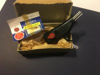
I am selling a new old stock pair of KR Enterprises VV32B, (300B), SET tubes for $600.00 USD. Although “Rare!” gets vastly over used in selling audio kit, these are, now indeed Rare! This pair is truly NOS and has never been used, except for 20 minutes of testing in my Bottlehead Paramounts! These are a beautiful, high output Western Electric 300B variant with a rugged heavy glass bulb. They are a factory matched pair. Boxes were opened for testing only.

The VV32B’s are interchangeable in most amps using the 300B-XLS tube, but as always, check with your manufacturer first! The filament amperage is higher than standard 300B’s, (2.0 amps v. 1.2 amps). Most amps have the headroom. Also the VV32B’s are slightly taller than standard 300B’s. Please make sure that you have room.

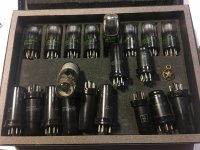
I bought these after hearing an amp running them at an audio buddy’s house. I am a long time SET guy. These tubes have the 300B midrange sweetness, but eliminate the roll off in the bass and treble. Both of my amps and preamp are 300B, but the Bottlehead amps cannot handle the higher filament requirement of the VV32B, (KR 300B XLS). So I was going to build new set of top-of-the-line 300B monoblocks, but, sadly. never did! (If you want a great buy on Electra Print VT2K output transformers, Audio Note 031 power transformers, Transcendar 10H chokes and these tubes, we could make package deal!)

The VV32B is an ultra-linear, low frequency, high power triode tube capable of producing 18-22 watts of pure class-A power. These tubes feature a new ribbon filament construction and the KR Enterprise exclusive patent design with 32 cathodes. The VV32B Series valves possess a vacuum of 10-9 Torr, a maximum grid current of 2.0 microamperes and absolutely constant emission over the life of the tube.

Average Characteristics
Plate Voltage....................400 volts
Plate Current.......................120 mA
Grid Voltage......................-60 volts
Amplification Factor...................3.9
Transconductance...................6000
Plate Resistance...............600 ohms
Load Resistance............2500 ohms
Power Output......................15 watts
THD..................................<0.05%

Maximum Conditions
Plate Voltage....................550 volts
Plate Dissipation................70 watts
Plate Current......................160 mA
Not Simultaneous Conditions

Filament Ratings
Voltage............5.0 volts a.c. or d.c.
Current................................ 2.0 A


Buyer pays USPS Priority Mail. insured. Shipping outside the USA is USPS International Express Mail. Tubes will ship within 48 hours of receipt and verification of payment. I will ship only to a verified PayPal address. Payment must be received within 7 days. Shipping cost is the actual USPS price. Please contact me if you have any questions before you offer. The tubes will be very well packed.

They are sold AS-IS. Sorry, NO RETURNS

k9PJqCB.jpg

ebvotJG.jpg

58a3avG.jpg

Terminal cups and internal wires

Hello,
I recently acquired a pair of MarkAudio Alpair 5.2 drivers with the goal of building the Woden BloodHound speakers.
I am now looking for the various pieces needed for construction of these speakers. I already have damping material but I don't know what pieces to get for internal wires and terminal cups.
I live in Montreal, Canada.
Any help would be greatly appreciated.
Thanks

3D Printed Metamaterials

(edit -- I originally said "wavelengths down to 1/46th.." Got wavelengths and frequency confused 😱 )

I ran into this paper - broadband diffusors that work up to wavelengths 46x the thickness of the diffusor. Looks like it would be a feasible 3D print (in a number or sections to get to the 52 inch width).

675942d1524086724-magic-metamaterial-diffusers-slice-png

See in particular, page 7 and table 4. (The deginitions of the parameters in table 4 are shown in Figure 1).

https://www.ncbi.nlm.nih.gov/pmc/articles/PMC5511165/pdf/41598_2017_Article_5710.pdf

These could be made into wall hangings only a little over 1" thick and work down to 250Hz! Get some grille material the same color as the walls and should be an easy sell to significant others who would hate traditional diffusors. If I work up the STL files, I'll post them.

Attachments

  • slice.png
    slice.png
    65.5 KB · Views: 1,629

impedance for PGA2311

good morning
I am making the printout for a volume control based on your indications, but I would like you to tell me how to do to prevent the CC from entering the PGA2311, and also what to do to adapt the impedance of my audio devices, because no one better than you can you solve the problem for me.
the first requires an impedance of 100k, the second of 22K and the third finally of 10k.
I thank you and I hope in your help a greeting to you all.
Guido Bullo

Use 2 output taps simultaneously?

I only ask this Q in an abundance of caution for an apparently unique intended application.

The amp is a British late 80s 25W dual EL34 w/3 output taps: 4, 8 and 16 ohm, designed by Peter Qvortrup.

If needed scroll down to Fig. 7 for the schematic here: Amplifier Audio Innovations Series 500

The speaker load has 2 discrete sections each with separate input and xo: primary section is about 9 ohm, the reverberant field section is about 25 ohm, both with moderate minimum impedance and benign phase angles.

Please comment on this intended application:
8 ohm tap > primary 9 ohm speaker section
16 ohm tap > 25 ohm reverberant field section

Or do you prefer?
4 or 8 ohm tap > 9 + 25 ohm in parallel

Of course I can try both and see which one sounds better.

Or...?

Please 'splain your reasoning.

TX!

FS: Maplin lateral mosfet update PCB.

I have done an update to the Maplin lateral mosfet pcb.
1/ Added front end decoupling for zero hum.
2/ Added DC offset pot.
3/ Added option for TO3 or TO247 lateral mosfets on PCB.
4/ Updated all other transistors to modern easy to find types.

I bought in 10 pcb's and keeping one for myself. Rest available to good homes.
£6.99 each plus p+p
p+p is £4.20 to UK
p+p is £11.99 to Europe.
p+p is £15 to rest of world.
Comes with parts list, schematic, power supply diagram and build instructions.
map2.jpg

Member passing Lukas Louw

Hey Ken, its Mary Ann, Luke's wife, I'm so sorry to do this over skype. We didn't know if he had your number or not. Luke passed away on Wednesday night. He was surrounded by the people he loved. Keep him in your prayers

a quote form his wife on the txt message i received.

I'm sure may will recognize his name from the forum on here. Lukas was a great guy , good friend, and a true lover of audio, not to mention a damn good engineer and designer.

He will be truely missed!

High current Negative rail generator

Hello

I am trying to design a circuit that runs off the 5v bus power of a USB port. In order to achieve more then +/-2.5 volts I figured a negative rail generator would be the most adequate solution.

After some research more IC can do this very easily with minimal external components, however current is limited to 10-30mA. My circuit needs around 100-150.

One product that I know does this is the Schiit Fulla headphone amplifier. It generates +/-5v from a USB port.

Any suggestions are greatly appreciated

FS: Diytube Get Set Go Bundle

Up for sale is a Diytube Get set Go Bundle with Opts, PT, choke, Sovetek 6a3 tubes, rectifier as 6sl7. The Board has already been assembled with the original Bom parts and was tested and fully working. The opts are edcor gxse 10 watt 3.5k primary with 8ohm secondary. The PT is triode electronics. No chassis. I have no time to finish the project... all it needs is a chassis and its ready to go. Asking $350 obo. Thanks

Conversion of active speaker to passive

O.k., here’s the setup.. I have a set of old Samson r5a’s that I want to convert to passive. They have 2 amps, 1 for the ribbon tweeter and 1 for the woofer. I want to remove the amps and just run the speakers as passive. I want to use the ribbon tweeter in them. I want to simply run an inductor on the woofer and a cap on the tweeter. What I want to know is twofold.. 1. Can this be done without destroying the sonic quality of each driver? 2. What inductor and cap should I use to run the woofer between say 50 hz and maybe 2500 hz and have the ribbon handle everything above that. The tweeter was designed for 25 watts and the woofer for 50 watts. I know this question will probably creat a firestorm of opinions, but please just keep it simple, we’re just talking 2 drivers and a gutted box. Lol

AC 125V (type A ) panel mount socket

Hi,
I am making a step down transformer for my friend in a nice box. I want to place a type A screw type panel mount socket in the back plate (it Japanese tube amplifier designed for 100V and its equipped with two prong Japan/USA style socket-I want it to remain original).

On ebay i found a cheap snap-in type but want a screw type. Maybe someone knows where to buy one in Europe at a reasonable cost? (shipping on e-bay very expensive from USA)

tnx.

Attachments

  • s-l500.jpg
    s-l500.jpg
    19.2 KB · Views: 86
  • s-l1600.jpg
    s-l1600.jpg
    80.7 KB · Views: 75
  • s-l1600.png
    s-l1600.png
    202.1 KB · Views: 76

First Speaker Build, Amping Question

Howdy, My name is Joe and I have been working on a speaker build for that past month. I've Worked on this same project in the past but college took my attention away from it. I'm new to the DIY speaker scene and I had a question on how to amp my drivers.

Currently I've got two drivers that I want to use in my build:

The Dayton Audio DC28F-8. Which has an RMS of 50W and is 8Ω

and

The Dayton Audio DS135-8. Which has an RMS of 50W, a peak of 100W and is 8Ω

One of the main issues with my build, is trying to find an amplifier that will run my drivers. I have a mock up design of my circuit that will get the signal to the drivers. I added a stereo amplifier before the crossover but this is not a stereo speaker build. I have a mono setup that takes in a stereo signal either from an AUX input or a bluetooth input. Then the signal is changed into a mono signal, then it is connected to the amp. After the signal enters the amp it is split into the two channels (at least this is how I presume it works). I was taking a shot in the dark and assumed that I could just connect each driver to its own channel but I'm not sure if I can do this. Below is my circuit.

Speaker_Circuit.jpg

I was wondering if I can do this with an amp. If both channels output 50W then they should power my drivers fine, right? Or should I get a mono amp and put my speakers in parallel (and change the crossover accordingly)? Or is there another way of completing what I am trying to accomplish?

Here are a couple of amps that I have been looking at for the past couple of days.

The TPA3116DA 100 watt mono amplifier

and

The TPA3116D2 50W x 2 Fosi Audio ZK-502C

If you have any suggestions it would be greatly appreciated if you sent them my way,

Attachments

  • Speaker_Circuit.png
    Speaker_Circuit.png
    91.3 KB · Views: 62

FS: 100% to Christian charity: Tribute Audio Finamet OPT, Luxman CL36U & drivers

For 100% to Christian charity items look on eBay:
Tribute Audio Finemet output transformers, 4.3K 50W PP
Luxman CL-36u Ultimate - Beautiful fully engraved faceplate, in need of restoration SOLD
Scanspeak Limited Edition 15W/4524T02 mid-woofers
Acoustic Elegance TD6M-4 mid-range speaker drivers
Acoustic Elegance TD6M-8 mid-range speaker drivers
LITTLE DOT MKIII Vacuum Tube Headphone Amplifier

huge collection of DIY electronics, parts, half built projects and PC parts

  1. 4 x Bob Cordell 3886 boards almost completely built (the 3886 chips are new and not soldered and included).

    All parts bought from mouser and all top notch. there are no cheap, no name, or used parts. Everything new, everything top notch price $199 for the 4 boards with including the 3886T chips. i have paid so much attention and care building them so far and have tested them . all 4 are 10/10
    ho5Xl1b.jpg

    gaYInA6.jpg

    NVH0l2y.jpg
    [/IMG]
    mjKoCh9.jpg


  2. 4 x salas sslv 1.3 ultra Bib boards. price $79
    all were working at some point but i cant guarantee since i havent tested since i pulled it out. i used them as the power supply for my sorkris DAC for a year.
  3. 1x salas digital power supply 3.3v price $29
    (picture above)

    in total there are SEVEN SALAS ULTRA BoB 1.3 boards.
    Two of the ultra boards have been built with all high quality parts (nichicon, vishay, panasonic, etc) and used as the power supply for my own DIY DAC but when i was taking them out i think i pulled hard on the transistor's legs so now two transistors work intermittently ie their legs are defective. I have the replacement transistors

    two other ultra boards have been 95% built but missing a couple components. all are for 12v. if you want a different voltage you need to change one transistor

    the digital board is 3.3 volts output and is built completely but not tested probably fine but dont plug in your expensive electronics to it before testing the output voltage with a voltmeter

    3 boards are new shiny and unused.

    8V2Tfng.jpg

    lbBCXaU.jpg

    jmCMYRM.jpg

    Dkdodqw.jpg

  4. power supply with huge bank of top of the line nichicon caps $59
    8yHrxv2.jpg

  5. Thermalright IFX-14 CPU heatsink with AM4 and intel 115x mounting system $34
    250 watts cooling capacity
    CRYel9j.jpg
    [/IMG]

    JNlwp2d.jpg


  6. 2x ultra silent 120mm CPU fans enermax
    $9 each

    CqB6Fwv.jpg


  7. Cavalli liquid spark headphone amp like new
    price $74

    1nW9mLg.jpg


  8. Thermalright ultra 120 eXtreme cpu heatsink
    250 watts cooling capacity like new
    intel and amd AM4 mounts price $34


    KwRqKNt.jpg


    jEvAu8N.jpg


    pQrFjjN.jpg


    eqQOyEI.jpg


    KwRqKNt.jpg


  9. low latency wifi card with great range $11 to add wifi to a desktop computer.

  10. SSD 64gb or 128gb. its new from a laptop that i bought and upgraded right away so it has not really been used free with any purchase
  11. intel laptop wifi card free with any purchase


    zoGemWK.jpg

  12. ifi power supply 5v , 9v, 12v , 15v all never sued but opened all together $179
    HuiFOhO.jpg


  13. vintage JBL speaker Lancer S99 local pickup near philly
    JBL TYPE S99 LANCER pair of vintage speakers, refoamed, recapped, and upgraded For Sale - US Audio Mart
  14. one RGB 120mm case fan new. free with any 3 items
    NAqYIUB.jpg

    this is the fan in the middle the rest of the items not for sale.
  15. Soekris 1021 DAC with AZ OLED board price $350 for the 1021 board, the AZ OLED kit, the coax input, and the power supply. so everything inside the chassis but not the chassis itself.
    Imgur: The magic of the Internet
  16. Rpi 3 never used with FLIRC all aluminum case $25
  17. pack of 9 new blank DVDs free
  18. 4x 3886 amp boards free (one of them has a few components in it.)

    MxQIhLN.jpg

  19. Two eminence Alpha 15A woofers $99 used but excellent
  20. RCA to XLR female 6 or 8 feet $11
    phKS9ER.jpg


    [*]keychron k2 rgb aluminum wireless and wired (both) usb keyboard barely used $55 with original keycaps. in the pictures below you see aftermarket keycaps. those are $20 extra

    https://www.amazon.com/Keychron-Wireless-Bluetooth-Mechanical-Keyboard/dp/B07WDBKHVM

    pictures: Imgur: The magic of the Internet


    [*]IsoAccoustics ISO200 subwoofer isolation platform - NEW
    link: Access to this page has been denied.
    price: $49


    [*]Solder sucker. Used. Free

    [*]Emotiva CX-2 used.
    price: $99

    [*]google home mini. opened box $12

    [*]set of 4 pangea SORBATHANE pico feet. price $18

    [*]monoprice XLR interconnects 6 feet pair $9

    [*]pair of IEC AC plugs
    2OurHQy.jpg
    $15

    [*]audeze headphone cable $15
    14xNth2.jpg

    not DIY i bought this pre made.


note: most items by themselves are not worth the trip to the post office. so i urge you to bundle a few things and add some of the free items if you want them
shipping is free for any 3 items for more.
Projects by fanatics, for fanatics
Get answers and advice for everyone wanting to learn the art of audio.
Join the Community
507,850
Members
7,890,716
Messages

Filter

Forum Statistics

Threads
406,370
Messages
7,890,716
Members
507,850
Latest member
saffer