Crossover question

Nelson posted this simple crossover for use with the SAL 08c08 with a 15" Eminence woofer on an open baffle. Any idea what the crossover point is for the woofer using this crossover ? I have a feeling the impedance rise at resonance will make calculations rather complicated .

Attachments

  • SAL8 OB PASSIVE W FILTER (1).gif
    SAL8 OB PASSIVE W FILTER (1).gif
    16.2 KB · Views: 95

Looking for a guide to using LTSpice for amplifier design

I am relatively new to LTSpice and wanted to find a guide to amplifier design using LTSpice or any circuit sim for that matter. Something that lines out what parameters you are looking for. How to measure them and make adjustments etc.. There must be something out there that walks you thru this process with some education along the way?
Doesn't have to be free either. I would gladly pay for it if its a worthwhile reference.

Jeff

Smoke came from TPA3116

Hi everyone

Please help me in ways to fix this problem with the tpa3116

I connected wrong terminals and saw some smoke coming out of the tpa3116 amp then i immediately pulled the wire out of the amp.

After connecting the correct wires it's now turning on but with these problems.

The subwoofer is giving very low sound.
When i connect more than 12v to the amp it disconnects the Bluetooth connection and sound start to break

Otherwise with 12v the two channels left and right are giving clear sound but very less sound to subwoofer channel.

Is there a way to fix this now.
Please check the attached pics aswell..

TIA🙏🙏

Attachments

  • 20201221_181525.jpg
    20201221_181525.jpg
    1 MB · Views: 159
  • 20201221_181512.jpg
    20201221_181512.jpg
    1,019 KB · Views: 162

18" woofer. Ideal for Open Baffle applications

Offering 12 each 18" custom designed OB woofers. Will only sell in pairs. Left over from a Manzanita product production run. Specs are perfect for OB applications. SD: 1,250 Sq CM. FS: 36 Hz. QTS: 0.8. Xmax: 5.5 mm peak.

This woofer is also great for PA audio applications with a minimal break up over 2 Khz. 8 ohms. So you can run them in pairs if desired. Large 80 oz magnet and 3" dual layer copper voice coil. Heavy pressed steel frame. $ 85.00 each Plus $15 UPS insured shipping to any location in the lower 48 US states.

For sale original Royd Audio speaker units

For sale original Royd audio bass mid and Scanspeak tweeter with original crossover with all new capacitors and resistors.So we have here two bass mid units,two tweeters and two crossovers.Verry good for soneone to build a pair of monitors or standmount speakers.Royd audio company is known for verry good sound.This units where in Royd Apex louspeakers.Price is 150 euro for all units plus shipping inside EU wich will be around 14-15 euro.For contact or offer pkese contact me.

Attachments

  • 20201219_175819.jpg
    20201219_175819.jpg
    812.8 KB · Views: 347
  • 20201219_175918.jpg
    20201219_175918.jpg
    981.6 KB · Views: 340
  • 20201219_175939.jpg
    20201219_175939.jpg
    986 KB · Views: 390

Sundown Audio SA2-3500D PCB Error

Hi All,

I would like to share a PCB error on the Sundown Audio SA-3500D PCB.

The source pin of Q77 is not connected to anything. The result is that there is only one IRF3205 driving the particular transformer. When driven hard, this seems to be a failure point.

I would love to know if others also have discovered it and know if this is also present in other versions of this amp.

Attachments

  • IMG_4256_C.jpg
    IMG_4256_C.jpg
    713.4 KB · Views: 100

6n6p Tube > Catodo Follower Polarization... Help Me! :P

Hi, I have a three stage phono preamp, v1 and v2 are ecc83 and in v3 I am implementing a Russian 6n6p.
The scheme is a classic ear834 type, or the old CJ and AR type preamps.
V3 is configured as follower cathode, DC coupled to v2.

I have a stabilizer circuit which provides two different b+.

One of 310v for v1 and v2 and another of 300v for v3 (6n6p).
Theoretically I can vary these voltages a little by acting on zener and / or resistors.

I would need some advice and hints for polarizing the 6n6p please. Here on various 3ds I have seen anodic voltages (6n6p) from 180v to 300v.

I also know with certainty that the 6n6p works well with currents of around 15mA.

On the v2 anode I have about 115 / 120v (Ra = 330K) which are reflected in the input of the 6n6p grid. I was wondering if you have polarizations to recommend ...

Are there too many 300v on the anode?
115 / 120v on the grid are too many?
Well if you give me a little help ...

😀 Thanks :wave:

Pioneer PD-M610 CD player - wobbly disc?

Hi all!
I received this 6disc CD player for repair.
Occasionally it does not want to read a disc.
If it reads the disc, the transport makes a ticking sound near the edge (last tracks) and sometimes it skips or gets stuck in a passage there.
You can also hear the ticking sound in the output audio as artifacts.
Lens cleaning did not solve anything.
I noticed the disc is 'jumping' up and down when spinning, as it is not level. It seems to be out of balance in the horizontal plane.
is this normal?
Note that it is correctly centered, it is not jumping from side to side.
I have checked the motor spindle but it seems ok, no play at all.

See this video:
Pioneer PD-M610 issue - YouTube

Any ideas?

I will also go through a full calibration, but I'm just worried that this wobblyness is not normal.

Adam Sub7 subwoofer PCU repair

Does anyone have any experience repairing Adam active studio monitors, specifically the Adam sub7 subwoofer? Are there any common weak points on these amps / boards / PCU's

It suddenly won't power on, the main fuse is good. The green LED's on the front panel no longer turn on.

I'm a novice with repairing & troubleshooting but can probe around with a multimeter and am handy with a soldering iron.

Visually I can't see any obvious component damage.

adam_sub7_pcu_amp.jpg


adam_sub7_front_panel_crosover_control_pcb.jpg

Elliot ESP P06 Preamp, Voltage at Inputs

Hmmmm...
I've just finished the P06 ESP phono preamp and I am getting a large voltage readings on the phono-in section. I've built a couple similar phono pre's and my voltage readings are 0 volts at the inputs. I'm having trouble sleuthing the problem, looking for ideas.

I built the variable EQ version for 78rpm EQ, so it is a bit different than the straight ahead build.

Getting voltage readings around 12.5 Volts at the inputs and no sound.
When I plug in my test turntable to voltage drops to around 2 Volts.

I've attached schematic of the version I built.

Any advice welcome!

Attachments

  • p91-f1.gif
    p91-f1.gif
    8 KB · Views: 290

1000W PA Quasi NMOS Amp - Class H Stepdriver possibile ?

Does somebody have experience or ideas

I want add Class H Rail Step driver for quasicomplementary NMOS amp 60/110 V DC?


but I remember in the past some diy member told me quasicomplementary amp does not working with class H Stepdriver (amp will oscillating in negative rail and burn up) ....but I think this information is not true , because its working in commercial NAD 208 70 V / 120 V Rail

NAD 208 is commercial Class H quasicomplementary NMOS amp

I think it can work if add Class H Step driver from apex member (900 W PA amp with limiter thread )

ANY ideas to increase efficiency for NMOS amp ? I dont like BJT output stage

Dayton ps-95 Build

After very long time I decided to build one small full-range speaker set for my small bedroom. It is based on Solo103 design but with changed ports length. Fortunately it came out with good bass and it's extending to about 60Hz, not bad at all for 3,5" speaker. I'm still busy with burn-in, I will report how it sounds when I placed them on the shelf...

Attachments

  • Dayton ps-95-1.jpg
    Dayton ps-95-1.jpg
    470.6 KB · Views: 1,438
  • Dayton ps-95-2.jpg
    Dayton ps-95-2.jpg
    467.4 KB · Views: 1,242
  • Dayton ps-95-3.jpg
    Dayton ps-95-3.jpg
    478.5 KB · Views: 1,160
  • Dayton ps-95-4.jpg
    Dayton ps-95-4.jpg
    334.2 KB · Views: 1,164

marshall 8008 mains transformer

i,m wondering if the mains transformer for my 8008 valvestate rack amp is broken


measuring 30 volt between red and black wire
measuring 30 volt between red an brown wire
measuring 30 volts between black an brown wire

shouldn,t it be 59 volts between red and black

Attachments

  • Marshall-Rackmount-2X80W-8008-Schematic.pdf
    Marshall-Rackmount-2X80W-8008-Schematic.pdf
    99.2 KB · Views: 109
  • IMG_5880.JPG
    IMG_5880.JPG
    74.4 KB · Views: 104
  • IMG_5881.jpg
    IMG_5881.jpg
    68.7 KB · Views: 124
  • IMG_5882.JPG
    IMG_5882.JPG
    97.3 KB · Views: 146
  • IMG_5883.jpg
    IMG_5883.jpg
    69.2 KB · Views: 111
  • IMG_5884.JPG
    IMG_5884.JPG
    83.3 KB · Views: 105
  • IMG_5886.jpg
    IMG_5886.jpg
    60.7 KB · Views: 111

DIY 2-way computer/desktop speaker build - help!

FINISHED: DIY 2-way computer/desktop speaker build - help!

Hello all, need your advice!

I am thinking of building a computer/desktop speakers. I have some parts (woofers and amp) laying around which I could use, but I have little experience in designing speakers.

Tweeter: ?
Woofer: SB Acoustics SB20PFC30-4 8" Paper Cone Woofer (Buying a SB Acoustics SB20PFC30-4 woofer? - SoundImports)
Amp: 3e Audio TPA3251 4x100W 4ch Class D (TPA3251-4CH-100W | 3e Audio)

So, my questions are, what tweeter would combine well with the chosen woofer? What would be the crossover frequency (I can program one for the DSP)? What should be the dimensions, internal volume, and should there be a vent? What kind of vent?

For the housing, I have plenty of quality veneer available, but I could also buy MDF. This build would be my second build as my first one was in school couple decades ago...

Cheers!

FS: Pair of ScanSpeak 18W/8531-G03 Sonus Faber series

Hello.
I do have a pair of mint ScanSpeak 18W/8531-G03. Only measured long time ago.
They are the same looking than the standard 18W/8531-G01 but specially made for Sonus Faber to be installed at Cremonas.
They came from Italy to be part of a project that will never happen, so I put for sale.

Price for the pair would be 230eur + PP fees + Shipping (between 20 and 30 eur)

I would trade for Audio Technology 18H52 as well


Marantz 1090 repair question

hello
If I may ask some advice here
I have a problem that I am wondering if I should try to fix myself or get serviced. I am in general pretty handy BUT very little experience with electronics.
my Marantz 1090 is making a really terribly loud and awful cracking noise. It sounds like this is a blown transistor? If so it seems like this is an easy fix, but not something I have done before. It's not that I have an aversion to getting it serviced by a professional, but I live in a very rural area and would have to expensively ship it, which I don't really want to do. So I am weighing how easy is that fix, how likely am I to mess up and make it worse?

Harman Kardon pm655vxi repair help

Hi Guys,

I need a bit of help with my PM655 Vxi unit. I bought it completly dead and I'm trying to fix it, but I've hit the brick wall and can't figure it out. The amp fries resistors R474 and R476, as well as Q430.

So far, I've replaced (as they were confirmed dead) the following, see the replacement too:

Q441 / Q442 - MJL3281AG
Q443 / Q444 - MJL1302
Q437 / Q438 - 2SC4883
Q439 / Q440 - 2SA1859
Q435 / Q436 - KSA1013YTA
Q433 / Q434 - KSC2383OTA
Q430 / Q429 - KSC945CYTA

I've also replaced the trimmers for the right channel and R439/R440 with 220Ohm resistors. It does damage the above 3 componenets, even when I plug a 100W buld into the PSU fuse.

Any feedback is much appreciated.

controlling front wall reflections

I was intrigued by the Jordon Aurora (photo attached, credit: Jordan website) as it claims to address the 'front wall problem' with what appears to be a simple and elegant arrangement. I've not heard it or seen a review. I don't now how it works, but it seems that it could simple re-direct the front wall reflections off at an angle and away from the traditional listening position.

The issue of the front wall is a new topic for me, I've never given it any thought in the past. I'm eager to learn from you 🙂

Attachments

  • Aurora_400_3567_web1.jpg
    Aurora_400_3567_web1.jpg
    30.7 KB · Views: 461
  • Jordan_Aurora_800_141118_D4S1396-1.jpg
    Jordan_Aurora_800_141118_D4S1396-1.jpg
    29.1 KB · Views: 469

Adding aux in to harmon kardon invoke

Hey all, I'm new here and clueless so if I'm posting this wrong I apologize.

My family has been using a harmon kardon invoke, a cortana powered smart speaker from Microsoft. It was great but unfortunately Microsoft is pulling the plug, issuing an update to disable all smart features and limiting it to Bluetooth only. The sound quality with bluetooth is a huge step down from spotify connect so I would like to add a 3.5mm jack for line in in order to directly play music or attach a spotify connect device.

I have only found one teardown (thanks Chris B from youtube) and in the video there are three empty headers on the main board (image attatched)
An externally hosted image should be here but it was not working when we last tested it.
. What do you all think about simply hooking up wires from a aux cord while playing music and trying various configurations on these headers?

Is this project even possible? Would it be extremely difficult? Any pointers or similar projects I could follow?

Thank you!

LII Audio, 8″ Fullrange Drivers, Silver-8

I am selling One Pair | New 8″ Fullrange Drivers | Premium level sound | Silver-8, brand new. Price 320€ + shipping. Location Europe, Slovenia.

They costs me 450€ with shipping + VAT.

link: One Pair | New 8" Fullrange Drivers | Premium level sound | Silver-8 - Lii Audio, unique speaker, amplfier, quality and cost-saving parts for HiFi DIY

Attachments

  • Silver-8-1.jpg
    Silver-8-1.jpg
    261.1 KB · Views: 663
  • Silver-8-2.jpg
    Silver-8-2.jpg
    184.6 KB · Views: 666
  • Silver-8-test.jpg
    Silver-8-test.jpg
    320.3 KB · Views: 657

HDI PCB - Higher Circuit Density, Higher Speed Signal

contact: info@pcbonline.com
website: PCB Fabrication and Electronic Components Assembly | Factory Direct Marketing
🙂
HDI PCBs are high-density interconnect circuit boards that utilize extremely small traces and vias to decrease the overall size of an electrical design.
HDI PCBs are also perfect for designs where electrical performance and noise rejection are of upmost importance. If you need to design a PCB with a high layer count and micro vias, then an HDI technology is the best solution for your needs.
PCBONLINE provides our customers with the highest quality HDI manufacturing services that can be found.

• HDI designs can easily meet the needs of high-speed signals for improve signal quality.
• These designs offer tighter pitch and thinner traces, micro vias, and an overall higher density of copper connections per square centimeter.
• HDI designs have great impedance control and impressive high-frequency transmission capabilities.
• Significantly reduce the radiated emissions of your circuits, improve the signal integrity of high-speed signals, as well as allow for higher trace routing density.
• Perfect solution for fine pitch packages, flip-chip assemblies, and complicated BGA designs.

----------------------------------------------------------------------------
• We have a skilled team that is knowledgeable in high-precision via back drilling, quality PCBA processes, and overall highly complicated HDI PCBs.
• We ensure that your product's signal transmission integrity is met by using top-of-the-line technologies to reduce signal series inductance of through holes.
• We utilize a specialized surface treatment process for all of our HDI production lines.
• We have state of the art German machines for V-cuts, tabs, and stack-up management as well as Mitsubishi machines for laser drilling, Hitachi mechanical drilling machines, and processes for automatic LDI and AOI.
• We also utilize the best temperature cycling equipment to ensure that your boards are high reliability and stable over time.
• We strictly follow all current IPC standards and provide you with your completed boards on time.

Comparative VAS+cascode stage

I am trying out different types of VAS+cascode stage for lowest distortion. These are the ones I tested. Please ,suggest other ones I try out.
The stage must provide a current gain of 10, to bring the 1M ohm load to +/-30v 10khz.

Attachments

  • vas+cascode distortion.JPG
    vas+cascode distortion.JPG
    78 KB · Views: 1,152
  • vas+cascode distortion2.JPG
    vas+cascode distortion2.JPG
    79.6 KB · Views: 1,162
  • vas+cascode distortion3.JPG
    vas+cascode distortion3.JPG
    87.1 KB · Views: 1,138
  • vas+cascode distortion4.JPG
    vas+cascode distortion4.JPG
    116.1 KB · Views: 1,159

Transformer Lead Routing.

I have a vertical mount power transformer, Hammond calls this 'X' mount. To make it fit in my chassis I wish to make it horizontal or 'Z' mount. For the intended X mounting the leads come out both sides of the laminations. To mount it horizontally I can feed one side's set of leads through the core to the other side. This will add or subtract half a turn. I intend to tape down this half turn with regular electrical tape. Is this sufficient or will there be unintended consequences.

remote mute/unmute of ecasound

I'm trying to get ecasound running as a multitrack player that allows me to selectively mute/unmute tracks remotely while it is playing. I've got it pretty close to working, but am stuck on one issue. Right now, I am able to get ecasound to start playing two mono tracks (sent equally to both L and R speakers), via


Code:
ecasound -a:1 -i track1.wav -erc:1,2 -epp:50 -a:2  -i track2.wav -erc:1,2 -epp:50  -a:all  -o:alsahw,2,0  --server


which starts both tracks playing immediately, and then, in a second process, selectively mute or unmute one of the two tracks (chains?) via


Code:
echo -e "c-select 1\r\nc-mute on\r\n" | nc -w1 localhost 2868


(this will mute chain 1, i.e. track 1, I can choose the track via the c-select command and the mute state via nc-mute)


The problem I'm running into is that I'd like to start ecasound with all tracks muted, but playing, and only then start remotely unmuting selected tracks. I've tried adding -chmute:1 after -a:1 when starting ecasound for example,


Code:
ecasound -a:1 -chmute:1 -i track1.wav -erc:1,2 -epp:50 -a:2  -i track2.wav -erc:1,2 -epp:50  -a:all  -o:alsahw,2,0  --server


and this will mute track 1, but I cannot unmute it via the remote process; it remains muted (note that the same remote unmute command will work if I start ecasound without any chmute and then mute track 1 remotely). So somehow -chmute is muting tracks in such a way that I cannot remotely unmute them. Any ideas? I don't want to start ecasound with everything unmuted and then remotely mute all; the remote interface latency is too slow.

Eidetic GB-1b needs help

Hi everyone, just yesterday I received an Eidetic GB 1b amplifier in generally very good condition, if a little dusty internally. I cleaned it out a bit, checked the output fuses and cleaned the terminals and fired it up with a DMM on each speaker terminal to check for DC. Both outputs showed 500mV initially, after 20 minutes warm up the RC dropped down to 60mV (still way too high for my liking) but the LC stayed at the 400mV mark.
Since there were no buzzes or hums, I tentatively connected it to my extremely sensitive Sansui SP300 speakers, now 52 years old and still wonderful, a high pitched pop at switch on (usually a muted slight thump with the DIGI 125) and all was well for 30-40 mins or so, then a sparkly crackling began in the LC and I disconnected immediately with no issues.
Ok, so I have a little information gleaned from this site and little else, is there a proper circuit diagram available anywhere here? Maybe there is a leaky cap or two on the main boards, but I am not familiar with Mosfet circuitry and all the caps will be 30+ years old now. The amp is #327. The main filter caps are all in unmarked silver cans, so I have no idea of the capacity yet.
The other thing is, since it comes with no user manual as such, I have no idea how to change the rear 4-8 ohm/1-2 ohm plug on the back ... yes I know it pulls out, but there is an inner lug on the plug that only allows for one way of orientation. Does the plug need to be removed for 1-2 ohm use? I have no idea.
Any further information would be very valuable to me, as this one will be a work in progress. As it is, it comes nowhere near the standard of my tuned up DIGI 125 and I'm keen to have it in tip top shape.
I'm considering replacing the 10uF 35V input caps with some Nichicon Muse BP versions that I've just received from Digikey.

*** I also would like to know about the second version which uses the OPA627 input op-amps, are they just a drop in replacement for the LM357s, or are there a couple of other items that need adjusting to make those OPA627s work correctly? I have no idea yet which trim pot may be used for DC adjustment or bias.
Any help here would be much appreciated! Is Greg Ball still around on this site?

Alpine MRP-F240

Good evening

Trying to figure out why pin 4 of the 494 is at 4.36v. Pin 3 is only 0.078v. Not sure why it's not being pulled down to allow the amp to turn on. 🙁

I have the following readings on the 494:

Pin 1: 0.00v
Pin 2: 4.94v
Pin 3: 0.078v
Pin 4: 4.36v. ????
Pin 5: 1.65 v (nice saw tooth form)
Pin 6: 3.65v
Pin 7: 0.00v
Pin 8: 12.19v
Pin 9: 0.00v (No wave form)
Pin 10: 0.00v (No wave form)
Pins 11-12: 12.19
Pins 13-15: 4.94v
Pin 16: 0.00v

Thoughts? I've removed the rectifiers hoping it might isolate something but no luck.

Thanks in advance

Loudness controls

I thought,

It would be interesting if people could add links or circuits for Loudness controls for tube circuits..I noticed some people still use them..🙂
I guess it would be interesting for comments as to the the use<<or are they worth using??
If they are worth using which topology is the preferred and why?? (Passive, active, tapped volume,)

Regards
M. Gregg

Attachments

  • Loudness ab.jpg
    Loudness ab.jpg
    73.6 KB · Views: 1,165

Power Supply design for multiple modules

Some advice would be apriciated.
I'm placing multiple modules, relay boards, relay volume controls and preamp pcbs in a chasis. They require multiple different voltages.
24VDC
12VAC
12VDC

Can I take a 12-0-12 transformer and tap off as shown in the attached? (Caps etc not shown)
I'm wondering if the common ground will cause an issue?

🙏

Attachments

  • 20201227_135426.jpg
    20201227_135426.jpg
    445.8 KB · Views: 200

turning on a aux unit by the on/off volume pot on the class d amp

This might be a strange question and currently outside of my skill set.

I have two items, one being a low voltage 5v class D amp,

5wx2 stereo dual channel digital amplifier board pam8406 audio amplifier module 5v class d amplifier Sale - Banggood.com

and this cheapo music player.

Bluetooth 5.0 mp3 audio decoder music player usb tf fm radio dh digital decoding module diy sound home speaker amplifier Sale - Banggood.com

I'm currently looking at how to integrate the two of these objects into a 3d printed build, but noticed that the amp's pot turns the unit on, which made me think, can i use this as a SPST switch or similar somehow?

This is going to be used for a 7 year olds boom box and be plugged into a 5v power supply via the wall, so want as least amount of switches etc to turn this on.

Can it be done and if yes, how does one do it?

If no, no big deal, ill just look at another amp i may have sitting around.

Up2StreamPro from Arylic Store - I2S interface

This Board has I2S interface with these 7 pins output;
Mclk, BClk, LRCK, Data, Gnd, SPDIF, 5Vdc.

I like to interface to my DAC I2S, it seems that my DAC don't have a MCLK pin. I connect the two boards together without using the Mclk pin(left floating). I can get audio output but I can hear digital noise. Questions please:

1. Do I have to terminate the Mclk pin to Gnd?
2. If so with a resistor, 10 or 50 or 100ohm?

Any suggestions thanks.

New stereo system - which one

Hello everyone,

after seeing Steve Guttenbergs Interview with Nelson Pass on Youtube, I have become interested in Nelson Pass designed amplifiers.

As it happens, I have never owned a decent stereo system. I am ready to upgrade and allow music back into my life.

I was wondering whether you could share your thoughts regarding my plan to build an Aleph J with a Nutube Preamp and match it with speakers.

Would you recommend this build? Which good speaker combination are you aware of? Would the Tekton Lore Reference or Klipsch RP 600 M be a good match?

Thank you for your kind consideration.

H-frame or W-frame OB bass?

I made simulation of H-frame (https://www.hifizine.com/files/2012/03/H-frame.png) and W-frame (https://www.hifizine.com/files/2012/03/Linkwitz-W-frame.png) in Akabak 3.
Both had frame depth 30+30 cm, double SB34NRX75-16 speakers in push-pull configuration, equalized in same way but results are significantly different.
Is W-frame force cancellation and smaller height better than H-frame higher response level, better on axis and polar plot responses?

In H-frame push-pull configuration distortions are partially compensated.
I presume in W-frame distortions are not compensated as much as there are different volumes (and air mass) on front and on back side of the speaker cones and speakers had direct pressure influence on each other.

What you prefer to build?
Or better is something in between like M-frame push-pull: https://www.hifizine.com/files/2012/12/M-frame-pp.png

Images are: 1. Low shelf bass compensation, 2. Dipole peak EQ, 3. H-frame on axis and 90 degree responses and full polar plot (Akabak had some bug in polar plot in -150 - -180 region) 4. same for W-frame.

Attachments

  • LowShelf1.PNG
    LowShelf1.PNG
    31.7 KB · Views: 456
  • PEQ1.PNG
    PEQ1.PNG
    33.1 KB · Views: 441
  • OBHframe1.png
    OBHframe1.png
    237.5 KB · Views: 455
  • OBWframe1.png
    OBWframe1.png
    289.7 KB · Views: 462

Horn sub driver, low or high MMS?

Hi! I`m interested in replacing my bass BR-boxes with hornsubs, in case this would be a better match to the rest of my system, which is horns. I`ve loked at different solutions, that it seems that a lot of people are happy with, eg the F-20, see Lilmike's Cinema F-20 | AVS Forum or Bill Fitzmaurice Tuba HT (the low profile version would be best fit in my room), see Tuba HT.

I notice that in both of these subwoofers the drivers have high MMS, compared to the Faital 15FX560 (see FaitalPRO | LF Loudspeakers | 15FX560 (8Ω)), that i use in my BR-boxes (two in each 200l box).

Would the bass from the hornsub still be fast and snappy compared to the BR-box? Is the high MMS necessary for the extension, or is it also to get the necessary mechanical strength?

I would sacrifice some extension for fast, articulate bass, if that is the tradeoff. 30-100Hz would be good enough, but with high efficiency. Above the bass I have 4 horns covering the rest of the frequency band.

Choosing parts to embed sound system in a desk.

Hi there!
I'm making a hollowed desk in which I want to embed a sound system which will be connected to a computer. And I'm a bit lost as how to choose speakers, amplifier, crosswalk and so on to get something as good as possible in the end.

The space available for each side (L and R) is a rectangular boxe of about 11x25x4.5 cm. The thickness is quite limited as you can see. The speakers will be shouting up through a metal holed plate.
Within this space I thought we could fit a 4" woofer + a tweeter. Though I am not sure if this would be the best option? Alternatively it could fit 2 full range 4" speakers.
How would you select the speakers? What about the power I should choose for a multimedia use? I think 2x15W is probably enough. And what about the amplifier and crosswalk?

Currently I selected those :
Woofer: AIYIMA 2Pcs 4 Inch Speakers Woofer 2 Ohm 15W Bass
Tweeter : AIYIMA 2Pcs 2 Inch tweeter 6 Ohm 30W
Are those two meant to be together? The woofer is the highest power I could find that can fit within 4.5cm. Though it's rated 2ohm. Is that a problem? I read in TPA3110 datasheet that it can drive speakers as low as 4ohm. So I wonder if that will be a problem. Also are there rules to match a woofer and a tweeter?
Amplifier : For the amplifier I will make my own PCB because I need to put other stuff on it (buttons that will be used for other stuff).
Now the question I have is which chip should I use. I found several which seemed to be good, not too expensive and about 15W : TDA7297, TPA3110, PAM8610, TA2024
They seem quite similar. Though if I have to choose one I would use a SMD one as it don't need the big heatsink of TDA7297.
Then the second question I have is how do you choose the different capacitor package, type and brand? As it seemed from my reading that it has a big influence on the sound quality. Also how do you select ferrites? If someone has parts suggestions for TPA3110 for instance? Or another chip as I have not started yet.


Crosswalk : I have actually no clue how to choose it as there are lot of different price ranges. For instance in this shop: Buy Products Online from China Wholesalers at Aliexpress.com
Which would you advise? Is there a real difference between a 2€ crosswalk and a 10€ ?
Is there a reason why the crosswalk is usually not on the same PCB as the amplifier? Can I put them all in the same PCB? If so how do you choose required components? If someone knows of a reference schematic/BOM I'm interested 🙂
Thanks!

Acoustic Exciter (DIY Tonewood amp)

The project: a small portable setup that feeds a guitar pickup signal thru a processor and back into the sound chamber of an acoustic guitar. Hopefully done with just enough power not to create a feedback loop but to provide ambient effects to the sound. Tonewood started it with a magnetic box stuck to the back of a guitar, Kepma acoustifex has a soudhole pickup/speaker.
But now manufacturers are providing it in their models likeLAG Hyvibe and Yamaha Transacoustic

I will be using a magnetic acoustic pickup and irig for the processing. It has a headphone out.

The exciters I think will use are the Dayton Audio DAEX13CT-8 3w or 4w coin type exciters. Dayton does have a small rechargable battery amp combo but i dont think it has an input other than bluetooth.

I already have a 20000mah powerbank that puts out 5v in 2.4A or 1.0A.

Suggestions for a small form factor amp to drive these?
or other suggestions?

question about plywood for Alpair 11ms dMar-Ken

Dear forum, I recently order to Dave from planet10 the planset to build the diamond shape for the 11ms. I had some leftovers of baltic birch plywood 18mm, but no enough to do this project, so I went to my local store and ordered some cuts. But they did not use birch, but PINE instead. Much lighter and not so dense, but it is a pity to have it cut for nothing (even if they gave the money back...) So my question is, shall I use that material or just pay for the baltic birch?

I attach photo of the material. Thanks all!
Captura%2Bde%2Bpantalla%2B2020-12-28%2Ba%2Blas%2B14.43.29.png

DAC blind test: NO audible difference whatsoever

(UPDATES BELOW)


That blind test was long due, it's now done.

Started with a 30$ unit (Fiio) against a 3000$ one (Forssell) and once SPL-matched (massive gain difference), no one could tell the difference in a ABX test.

Then, we switched to a different set-up, using a pair of B&W CM9 speakers and the Forssell against a Eximus DP1 (3500$ or so). Same result: impossible to spot them in a ABX.

We were only 4 participants, but regardless it didn't feel like day & night difference to start with... ''Eyes opened'' we FELT differences, but couldn't prove it in the ABX.

Cables, amplifiers, Lossy v.s. Lossless/HD, EQ'd mid drivers, DAC... Nope. Nothing is passing a ABX blind test.

I'm pretty sure, now, that the human auditory capacities are very, very, overestimated. 🙁

The good news is: we can probably save a LOT of money.


-------------------------UPDATE 14th Nov 2017------------------------

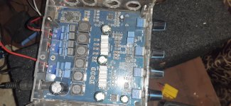
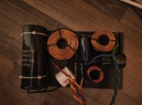
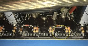
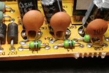
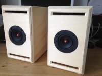
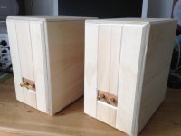
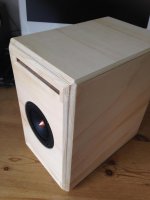
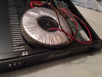
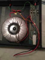
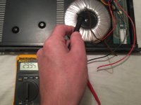
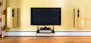
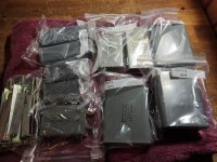
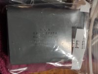
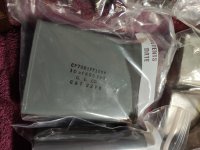
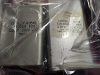
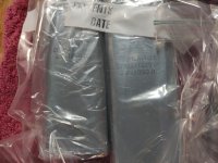
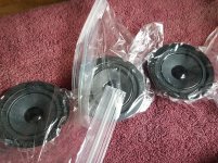
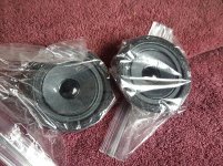
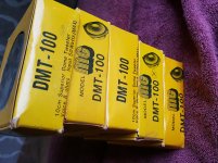
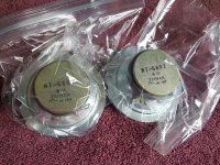
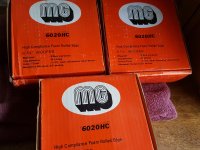
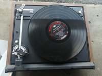
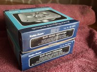
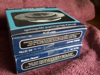
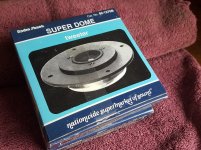
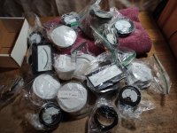
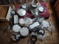
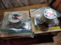
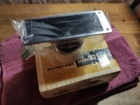
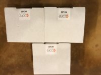
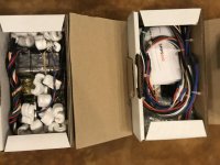
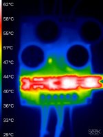
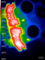
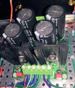
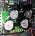
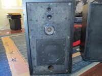
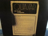
Here is some pictures, including the whole room while we change set-ups (the 3rd one is on his way...)

An externally hosted image should be here but it was not working when we last tested it.

An externally hosted image should be here but it was not working when we last tested it.

An externally hosted image should be here but it was not working when we last tested it.

An externally hosted image should be here but it was not working when we last tested it.


-------------------UPDATE 16th Nov 2017-------------------------------


System set-ups #1 & 2 were very useful to spot the possible weaknesses of the whole process and equipement. So today was the Day 1 of the system set-up #3, which includes the following changes, based on observations and also comments and thoughts on this very thread:

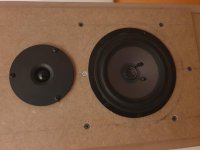
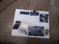
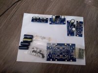
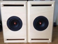
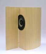
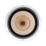
.: New DIY speakers including Faital Pro 18FH500 and ribbon tweeters RAAL 140-15D.
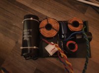
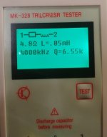
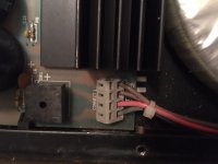
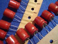
.: High quality Solen passive crossover components, including dual Film & Foil capacitors for the tweeters.
.: Instead of iTunes and a computer, we used a Astell & Kern AK300 as the source (Toslink direct line out).
.: No switchbox anymore, a manual switch is made with each pair of RCA cables, in a way the participant cannot know.
.: Larger selection of music to choose from.
.: Shorter AND/OR longer music excerpts duration, whichever makes the participant more comfortable.
.: Uncompressed and also some 24/96 music files.
.: Closer distance to the speakers, from a previous 3,12m to 2,25m.
.: Better SPL-matching, using pure tones and double-checked with 2 differents mic.

Basically, to our actual knowledge, everything was carefully made to optimize the chances of a positive identification in that 3rd and final attempt. That test will continue to run for few days, we welcome participants from DIYaudio. Here are the first results:

3rd set-up - DAY 1

First participant was there last sunday (set-ups #1 & 2) and, sighted, was optimistic about his chances. Felt confident that changes made was for the best. FAILED to identify on every music excerpts.

Second participant, non-audiophile, male 34yo, and did not participate previous rounds. FAILED to identify on every music excerpts.

Comments collected afterwards was unanimous: even sighted, the potential audible differences were extremely thin. They both felt they could grasp some hints, but they didn't made it, through the test. They were the most confident with the 24/96 music file Angel of Harlem from The Persuasions and the 16/44 Ungear Moi from CoH, but it didn't change the results whatsoever compared to other music files.

Conclusions of Day 1: From a very promising 3rd set-up, the hopes are now getting extremely low to find a participant who will be able to spot the 19,99$ DAC from the 3000$ one. We already know that 100% of the population is now an impossible target, we do hope that in the next days we'll find new participants that will get better results.


3rd set-up - DAY 2

3rd participant, non-audiophile, male 35yo, and did not participate previous rounds. FAILED to identify on every music excerpts.

4th participant, audiophile background, female 42yo, and did not participate previous rounds. FAILED to identify on every music excerpts.

5th participant, non-audiophile, male 45yo, and did not participate previous rounds. FAILED to identify on every music excerpts.

6th participant, non-audiophile, female 40yo, and did not participate previous rounds. FAILED to identify on every music excerpts.

7th participant, audiophile +DIY background, male 40yo, just passed audiogram (8dBHL, symmetric). FAILED to identify on every music excerpts.

A curved ribbon

Some time ago I made a couple of full range ribbons, 110 cm long, of which I described the construction in another thread of mine. Since then I have listened to them both dipole mounted and in closed box and with different types of music, and I must say that I liked them much more in closed box. In addition to being less critical with respect to positioning, closed box ribbons are definitely superior when listening to percussion instruments. The response to transients is exceptional, everything perfect, except the spatiality. By spatiality I mean perceiving the reproduced sound as if it came from instruments actually present in the room. I have found that those who say that tall ribbons should be listened to as if they were headphones are right, with the listening point between the two sources. The side effect that summarizes what, in my opinion, is the defect of long ribbons is this: Listening to the music while seated, the orchestra and the singer are located in a certain position, but when you get up, the orchestra and the singer are also raised . This effect evidently derives from the directionality in the vertical plane of the tall ribbons, an effect that I mistakenly considered positive in all respects, believing, based on what I had read, that the reflections from the walls were an effect to be avoided. I changed my opinion and now I believe that the reverb from the walls is not only natural but necessary for the effect of spatiality. Following this idea I want to experience listening with an almost point-like source, while maintaining the sound quality of the ribbon, and for this I started the design and construction of a curved ribbon.
Of course I am aware that a thrue ribbon cannot be curved, so I will resort to the side suspension construction, which I have used in my previous ribbons with good results. The principle to follow in the construction is simple: The ribbon is held in place by the lateral suspensions, while the terminal connections serve only as electrical connections without exerting any mechanical force.

Difference in sound qual. between SEAS Excel W18E-001 (E0018) vs. W18EX-003 (E0074)?

Hi
I had a question for the panel here to see if anyone has any listening experience between the following SEAS 7inch drivers:
SEAS Excel W18E-001 (E0018) and
SEAS Excel W18EX-003 (E0074)

The W18E-001 is used in the Thor and Odin designs and I am building a Thor but with an active crossover.

I noticed that the more recent W18EX-003 is about $200 more per driver and I wondered in there is a quality difference in the sound. They do tout (on the Seas website) that the 003 is design for modern "high resolution" audio (which was not as prevalent when the 001 was designed).
I have seen the specs and evaluated the graphs but the numbers aside - Is there a sound difference that is clearly discernable or do they pretty much sound the same (since they share the same Magnesium cone) and I am mainly paying for the "Graphene" coating which is really makes the driver more rust resistant and does not make a real difference in sound


Since the MTM design will require 4 drivers (2 per speaker) I wondered if it is worth the extra $800 expense for my drivers.
Basically will I repent not having gone for the 003's or its best to save my money and the added cost is more of a marketing gimmick?

Thanks

RCA Input Source to Two Outputs?

I am searching for a device that will enable me to switch between one source (Node 2i) and run the signal to either my Yamaha AS1100 or to an Elekit tube amp. I see plenty of devices that allow multiple inputs to one output, but can't seem to locate the opposite...


I wouldn't mind building one myself, but I'm not that experienced with electronics to both develop and build. Any kits? Or just a device I could purchase?


Thanks!

Counterpoint 3.1 manual and/or specs

Hello


is there anybody willing to share an e-copy of the Counterpoint SA 3.1 tube preamp?


I found the service pdf manual but I can't find a manual. I am pretty much on top of how it works, but I'd like to know some technical details such as gain of the line stage, gain in the phono stage, phono stage load, input/output impedance etc.


I hope in some help!
Pietro

Amp Mod Curiosity

Ok all you amp freaks out there....
I'm interested in this particular amp, however I'd like some advice on a few modifications to it.

This is a simple, yet advertised as a low-distortion (0.02 IM) 40 watt amp.
What I would like is some suggestions on removing the feedback-installed bass/treble from it, and instead using a "plain" system of feedback, keeping the amp as linear as possible without that stuff attached in the feedback line.
Essentially, like using with the bass/treble at "0".

Secondly, I'd like to UP it's wattage to around 80, maybe 100W, keeping the original design, but perhaps changing the output transistors, maybe the drivers as well. (higher B+, maybe +/- 65V?)

Nothing too drastic - I like its design, just toying with some mods.

Attachments

  • amp40W.JPG
    amp40W.JPG
    130.6 KB · Views: 240

Large flat Metal capacitors -- GE Cornell Dubilier SPRAGUE caps -- NH USA

$125 or best offer

Make offer in thread, need gone

Attachments

  • IMG_20201213_211739.jpg
    IMG_20201213_211739.jpg
    981.6 KB · Views: 218
  • IMG_20201213_211747.jpg
    IMG_20201213_211747.jpg
    540.2 KB · Views: 217
  • IMG_20201213_211750.jpg
    IMG_20201213_211750.jpg
    608 KB · Views: 202
  • IMG_20201213_211752.jpg
    IMG_20201213_211752.jpg
    580.7 KB · Views: 194
  • IMG_20201213_211754.jpg
    IMG_20201213_211754.jpg
    380.1 KB · Views: 187
  • IMG_20201213_211808.jpg
    IMG_20201213_211808.jpg
    857.5 KB · Views: 95
  • IMG_20201213_211815.jpg
    IMG_20201213_211815.jpg
    627.1 KB · Views: 90
  • IMG_20201213_211913.jpg
    IMG_20201213_211913.jpg
    935.2 KB · Views: 77
  • IMG_20201213_211802.jpg
    IMG_20201213_211802.jpg
    806.5 KB · Views: 74

Cone tweeters - NOS tweeters woofers -- DUAL 504 turntable parts

Any interest in this garbage?
$999 or best offer.

Dual 504 is for parts, cover is gone and needle/cartridge is gone.
But I think it worked when it was complete.

Attachments

  • 20201130_115458.jpg
    20201130_115458.jpg
    1 MB · Views: 153
  • 20201130_115442.jpg
    20201130_115442.jpg
    1 MB · Views: 157
  • 20201130_115223.jpg
    20201130_115223.jpg
    992.3 KB · Views: 144
  • 20201130_115417(0).jpg
    20201130_115417(0).jpg
    1 MB · Views: 134
  • 20201130_115521.jpg
    20201130_115521.jpg
    983.2 KB · Views: 142
  • IMG_20191223_154027.jpg
    IMG_20191223_154027.jpg
    886 KB · Views: 92
  • 20201130_115257.jpg
    20201130_115257.jpg
    996.2 KB · Views: 105
  • 20201130_115325.jpg
    20201130_115325.jpg
    998.6 KB · Views: 82
  • 20201130_115320.jpg
    20201130_115320.jpg
    1 MB · Views: 90

Embarrassingly Basic Question :(

While waiting for Ghent's RTX modules to arrive (today marks 60 days of waiting), I thought I'd start addressing some of the basic wiring in the pair of ICEpower 1200AS mono amps I'll be assembling. It took only minutes to hit a snag. Specifically, the color-coded wires of the internal mains cables supplied by ICEpower conflict with the 1200AS documentation:

0PSb06r.jpg


The hot, brown wire should go to pin 3 of P100 and the blue to pin 1. The connector has the colors reversed. A photo of the interior of a Rouge amp using the same ICEpower board does show blue on pin 1 and brown on pin 3:

jkvSZSn.jpg


Safe to assume ICEpower erred in making the mains cables?

A little reassurance would be appreciated.

Completely new; maybe simple question

Am used to big box store home theater amplifiers; pioneer / jvc entry level between early 90's through to 2012 or so.

Ratings always 100w / ch.
for example last avr I bought as new;
pioneer vsx-522(2012) power supply 415w....funny note, I had googled the release date, and first line I read is from pioneer ".....With 700 watts of clear audio reproduction..." lol

I recently picked up an NAD T747 (2010).
It's rated at 110w stereo, 60w 7 channels driven. (both 20-20k / .08thd)
The power supply is nearly same power as the pioneer; 420w.

In stereo, the NAD sounds much more powerful. It can drive much bigger speakers and maintain clear sound.

In fact in stereo, the NAD sounds comparable in power availability to drive speakers, as the onkyo sr-tx809 which is rated 135w and has a 900w ps. (9 channel avr)

So that highlighted to me dichotomy / components of power supply section, and amplifier section.

The entry level NAD has amazing amplifiers. The power supply, like many brands, is insufficient for powering all the amplifiers to their max spec.

Which has me wondering, less the "auxiliary" power supply windings, can I power the NAD's amplifier with say...the 900w onkyo power supply? Does ht amplification work as my simple reasoning figures; is this possible?

Snell LCR7 XL crossover schematic

Hello, I have recently bought 4 Seas W15CY001 and 2 T25CF002 Millenium for a low price and I’m trying to build a clone of Snell LCR 7 XL . I have listened to these loudspeakers some years ago and I was impressive for the detail and the clean stage. I have look at the review at Stereophile and Audiholics to design the same crossover but after some tentative the results were not as expected, there must be something hidden.
By chance, does anyone has the schematic of the crossover of these beautiful loudspeakers?
Thank you

What's the best pair of bookshelf speakers for under $1000?

First of all, my apologies but there does not seem to be a topic like this discussed in recent history.

What I'm looking for is the most perfectly neutral bookshelf speaker pair (kit, assembled or plans) for under $1000. Flat frequency response and able to take 100W or so. I am trying for a sound at least as good as my BGcorp RD50 ribbons.

I have tried the Proac 1SC clone, Ascend Acoustics CBM-170, KEF C20 and Klipsch RB-81. The Proac clone sounded best to me but rather than audition every bookshelf speaker available, I thought I'd ask...

"What's the best pair of bookshelf speakers for under $1000?"

Bsl-mb1200 repair

Hi.

I have a bsl-mb1200 mono class d amp (i dont know the brand, maybe blackmore). It comes with ps fried, 50n06. The output inductor is fried because an output mosfet in shortcircuit, 33n20.

At the output section has an ir2011 mosfet driver. But near this ic, had 2 little ic fried and i dont know what part it is.

Anyone have or seen an amp like this? I dont know if it worth fix it but i will try.

Attachments

  • 20201118_213521.jpg
    20201118_213521.jpg
    778 KB · Views: 116
  • images (5).jpeg
    images (5).jpeg
    3.7 KB · Views: 93

Magnum md250.4 irs2092

Hi everyone. Im working on a 4 channel class d amp with irs2092 ic and irfb4227 oitpit mosfets.
The 5v regulators has failed, so all 4 ics fail. Im waiting for the irs2092, now i have only one channel working.

The problem is it had 2 diodes shorted on 2 left channels, and i dont know the value. In the picture the diode is the d6. Its conected to csh pin with a 6.8k ohm resistor.

Irs2092 datasheet says use bav19ws diode, others diagrams use mur120.

Anyone have info about this diode?

Thanks

Attachments

  • 16083444771987441563422946491211.jpg
    16083444771987441563422946491211.jpg
    994.2 KB · Views: 113
  • 16083445022558531726120787296125.jpg
    16083445022558531726120787296125.jpg
    713.8 KB · Views: 110

(3) Hypex NC400 amp modules, (4) SMPS600 power supplies, (2) nc500oem amp modules

(3) Hypex NC400 amp modules, (4) SMPS600 power supplies,

I have 3 nc400 Hypex modules. These are Hypex, not rebranded. Untouched. $300US each.

Also, I have 4 Hypex SMPS600 power supplies, untouched. $125US each.

Disregard photo of the nc500oem's- they are in a different ad.

Buyer pays shipping from Wi, USA. Payment via paypal.

Photos below.

Attachments

  • nc400.jpg
    nc400.jpg
    665.1 KB · Views: 638
  • smps600.jpg
    smps600.jpg
    750.2 KB · Views: 635
  • nc500oem with power supply.jpg
    nc500oem with power supply.jpg
    520.7 KB · Views: 619

CCS capacitor

Sorry it this is kind of a basic question. I'm trying to get my head around common circuit designs for three stage amplifiers.

I have seen several schematics where the current source that feeds the LTP has a capacitor from B+ to a voltage divider between ground and the base/collector. An example of this is C3 and R7/R9 in the attached example.

e85cics07iviqx1sayf52ayu


As far as I understand, the purpose of this is to stabilize the bias point of the transistors making up the CCS, but if someone could elaborate a bit more around this circuit block, it would be really helpful. What is the benefit of having the capacitor connected to a voltage divider here? To improve PSRR?

Thanks!

advice on multi-voltage power supply

Hi Folks,
I've breadboarded a JFet, class A mic preamp. (https://www.tangible-technology.com/ipr/AE230/html/wk_6/hamptone_fet_scan.pdf).

It requires 2 voltages:
  • 24V for Vcc
  • 48V for phantom powered mics

I'm currentlying regulating a 28V Mean Well wall-wart down to 24V, as shown in schematic.

For 48V, I'm using a 48V Mean Well wall-wart.

Even without the 48V (using a dynamic mic), the noise is high, "hiss" (not 60Hz).

For the PCB version, which I'll design soon, I could use advice on how to build the dual-voltage power supply. (i.e. voltage doubler for 48V? dual-secondary transformer? all linear, remove the regulator?)

Requirements:
  • 24V for Vcc
  • 48V for phantom powered mics
  • budget / affordable
  • low noise
  • small-ish component count (I can design PCBs, but if it gets too complex, I will not complete it)

Thanks for any ideas!
BW

PCB available: PSU for Chipamps , such as Super Gain Clone and Compact3886

To build stereo amplifiers using LM3886 chipamp ICs, I decided I needed a small PSU board, quite a bit smaller than the "Universal Power Supply PCB" sold in the diyAudio store. This is the result. The new board is 78mm by 98mm and its mounting holes are (7.0 cm by 9.0 cm) apart. Its holes line up with the 1cm grid of holes in the chassis floor plates of Modushop / diyAudio Store chassis.

The PSU circuit schematic is shown in Figure 1, and its parts placement is shown in Figure 2, below. The PSU connects to a dual-secondary power transformer and provides dual rail (± XX volts DC) DC output voltages. The capacitors are rated for a maximum of 50V, and the diodes are rated for a maximum of 100V. This is plenty, since the chip amps themselves (LM3886) are only rated for an absolute maximum of ±42V supplies. Your power transformer's secondary voltage should be 30V AC (rms) or less, to avoid violating the LM3886 maximum rating on its DC supplies.

I have specified 10 ampere discrete Schottky diodes for the bridge rectifier, mounting two diodes per heatsink (Aavid 5132 or 5131) with thermal insulator pads between each diode and the heatsink. Schottkies were chosen because of their significantly lower forward voltage drop, which produces significantly lower power dissipation. Power dissipation is a concern because the diodes are mounted next to the large electrolytic filter capacitors. High temperature reduces capacitor lifetime, so we want low temperature, so we want low power dissipation in the PSU, so (I conclude) we want Schottky diodes.

THESE THINGS GET WARM!

Figures 3, 4, and 5 show infrared camera images of this PSU board operating at above-maximum load. It's delivering +27V at 4 amps, and also delivering -27V at 4 amps. I took the photos after 90 minutes of running at this condition. With ambient air at +27C, the heatsink temperature was +61C and the hottest spot on the electrolytic capacitors was about +50 or +51C. In my opinion, this is comfortably below the maximum operating temperature of the caps (+85C) and they will live a long and healthy life. Especially when you consider that the test conditions (constant max-DC current into a load resistor) are much worse than anything possible when playing music into loudspeakers. I've attached an application note by Cornell Dubilier (a well-respected manufacturer of electrolytic capacitors) that walks through Operating Life calculations for capacitors at elevated temperatures, if anyone wants to pursue that further.

I recommend using the two inch tall heatsinks called "Aavid 5132". Although DigiKey stocks and sells them, regrettably Mouser has a minimum order quantity of 750 pieces (!). Mouser does stock and sell the 1.5 inch tall version called "Aavid 5131". It does a good job but of course the taller heatsink does a better job. If you plan to run your chip amp at very high loudness for long periods of time, I recommend you expend the extra effort to buy the two inch tall 5132's from DigiKey. On the other hand, if you don't forsee blasting your chipamp at max loudness very often, I think you will be just fine with the 1.5 inch tall heatsinks that have no minimum order quantity.

OTHER COMPONENTS

Resistors R3 and R4 are "bleeders", which discharge the capacitors to zero volts when the power is turned off. This is a safety measure to protect repair personnel. R5 and R6 are current limiting resistors that set the current in power-OK indicators LED1 and LED2.

Each transformer secondary is connected to a snubber, which prevents LRC oscillatory ringing. The snubbers are (MOV1 + C1 + R1) on the positive supply, and (MOV2 + C2 + R2) on the negative supply. {"MOV" is an acronym for Metal Oxide Varistor; it's a bidirectional voltage clamp used in surge surpressors.} Snubber component values were chosen after testing on the Quasimodo test jig {described elsewhere on diyAudio} and verified on a completed amplifier using two LM3886s, playing music at full volume. MOV1 and MOV2 each have a capacitance of about 550 picofarads, which is the "Cx" component of the snubber. In addition to snubbing, the MOVs also provide a measure of protection against surges on the AC mains. However, if you are uncomfortable using MOVs in your PSU, feel free to replace them with 100V, 680pF film capacitors.

CHECK OUT THE DETAILED PARTS LIST

There's a spreadsheet attached to this post, which contains a very detailed Parts List for the PSU for Chipamps. Extra detail has been included to make it easy for you, the builder, to find parts whose electrical performance is acceptably good and whose physical size will fit the PCB. If one or more parts are out of stock or backordered, the Parts List is your savior. It will help you find a replacement that's just as good or better.

Also attached is a web link to a Mouser.com preloaded Shopping Cart. A so-called "one click" Shopping Cart. BEWARE: don't shut off your brain when using this; check to be sure that every line item is in stock and not backordered. Check to be sure you're not accidentally ordering 1000 of something. Be mindful.

HOW AND WHERE CAN YOU OBTAIN THE BARE BOARDS

I've got a few dozen extra boards that I'll sell for $2/board plus shipping. They're 1oz copper with gold "ENIG" pads. Maybe you might want to also order some Super Gain Clone chipamp boards and/or soem Compact3886 chipamp boards at the same time. At the moment (Nov 2019) I'm charging $2/board no matter which board you're buying. Shipping is $6 per order to USA addresses, and $16 per order to rest of world. Max 10 boards (total) per customer. PM me with quantity desired and to get my PayPal info.

If those boards sell out and there is additional demand, I'll organize a Group Buy in the GB section of the Forum. And if there is LOTS of demand, I'll show the numbers to the diyAudio Store people, maybe they might want to eventually offer these boards through the Store.

_

Attachments

  • Figure_schematic.png
    Figure_schematic.png
    69.3 KB · Views: 5,983
  • PSU_Gerber_image.png
    PSU_Gerber_image.png
    35.1 KB · Views: 3,245
  • Top_View.JPG
    Top_View.JPG
    166.8 KB · Views: 3,974
  • Oblique_View.JPG
    Oblique_View.JPG
    187.7 KB · Views: 3,886
  • Hottest_Spot.JPG
    Hottest_Spot.JPG
    162.7 KB · Views: 6,735
  • Diodes_front.JPG
    Diodes_front.JPG
    449.6 KB · Views: 1,288
  • Diodes_rear.JPG
    Diodes_rear.JPG
    313 KB · Views: 1,348
  • PartsList_PSU_for_Chipamps.zip
    PartsList_PSU_for_Chipamps.zip
    6.1 KB · Views: 441
  • Saved_Mouser_Shopping_Cart.txt
    Saved_Mouser_Shopping_Cart.txt
    119 bytes · Views: 403
  • CDE_Electrolyic_Application_Guide.pdf
    CDE_Electrolyic_Application_Guide.pdf
    414.4 KB · Views: 552

Hertz HDP1 - Thermal Protection LED ON but works fine

Hi,

I have an amplifier Hertz HDP1 and it is working fine. The only problem is that the TH LED is always ON. I checked the SW1 on the main pcb and it seems to be working fine. I followed the LED track and arrived till the board 37PW-HDP1-01 Rev:V0.0. I tested the transistor Q10 and it seems to be fine. The transistor is fed from R36 and D15 then from U3 (TL494C). Any hints what the problem might be? Thanks

Quasar QS1 Studio Speakers.

I've tried to find some info on these speakers online with no luck so far! I bought them from a guy who never used them and doesn't know anything about them except that they are good speakers that his musician friend had until he died a few years ago. So any info I can get before I dismantle them to replace the capacitors in the crossovers would be great. They are fairly heavy at about 20kg each.

Attachments

  • IMG_0142.jpg
    IMG_0142.jpg
    983.6 KB · Views: 586
  • IMG_0144.jpg
    IMG_0144.jpg
    862.5 KB · Views: 557

Yet another Adcom GFA-535

It's been a while since I posted something... Since I build a tiny O2 headphone amp back in the day.

Cutting to the point since I got my paws over a decent Gfa535 the first thing as man's nature dictates is to open it up and mess with the guts.
Simple beast with a few caps to be changed /upgraded. That is done and out the way.
Next step is to change big caps in the power supply... and then I realized something seems odd, even though it's a dual mono with mirror boards I noticed one (L) has and extra cable that runs to the power supply.

I'M a newB but there is something the way the grounds are done that seems confusing and TBH I can't quite comprehend the why's and if there is a way to improve it.
I searched the forums and the only thing I found is a guy that sells a new PS board... But what can I DIY? .. In the case there is room for some improvement in the grounding section.

NUTSHELL
1. Recap - pretty much done
2. New inputs - In process
3. Speaker terminal replacement (speaker selector is being erased plus new 5 way binding posts to come)
4. Q607 will be eliminated from the L+R boards. According to my Guru (dad which is/was and everyday DYIaudio member that actually read pretty much all the posts in the Blowtorch thread LOL) that Q607 gets in the way of the overall circuit just to flash some clipping leads. I don't prefer LEDs over sound quality.

Some pics for mere reference and schematic added.

Any input and comments welcomed!

Cheers from Mexico,
ROB.

Attachments

  • IMG_20200318_212330.jpg
    IMG_20200318_212330.jpg
    528.2 KB · Views: 741
  • 15847562095534128829965273211466.jpg
    15847562095534128829965273211466.jpg
    518.9 KB · Views: 792
  • hfe_adcom_gfa-535_service.pdf
    hfe_adcom_gfa-535_service.pdf
    296 KB · Views: 266
Projects by fanatics, for fanatics
Get answers and advice for everyone wanting to learn the art of audio.
Join the Community
507,764
Members
7,887,435
Messages

Filter

Forum Statistics

Threads
406,176
Messages
7,887,435
Members
507,764
Latest member
Szaboo41