Better living room acoustic systems surpassed by headphones

All acoustic systems, commercial or DIY, will never sound like a good pair of headphones. It is an incontestable and undeniable fact.
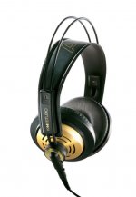
My room system is not the best, but it is not to devalue either, I have spent a lot of time and money on it, but I do not get with it the sound of my old AKG K-141, which I still use, and it is supposed to be outperformed by current models ...
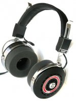
The Sennheissers were also superb, I remember the first ones (which were really ugly, but they used mylar diaphragms and that did the miracle.

Sennheiser HD 414 and 424 – Old School | TONEAudio MAGAZINE

The subsequent intensive use of this material wiped out the heavy eyes with transistor radio mini-speakers inside!
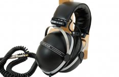
This was the Pionner SE 305, they were a Chinese torture, bad sound, heavy and suffocating.
Even a pair of mid-priced, recent manufacture Phillips headphones have bass with surprising resolution, my "room" system doesn't have "the one-note bass", but it's different, there's no transparency or harmonics that gives a good headphone in the low end of the spectrum.
My favorites were always the open system, (the air is not locked in the ear tunnel, breathe)
For example, I had Koss, I remember the HV-1A and the HVX, I had both. What transparency and definition they had!
So, if you want the best sound in the world for little money, you know ......

Attachments

  • 122-400x258@2x.jpg
    122-400x258@2x.jpg
    69.2 KB · Views: 296
  • HVX-1.jpg
    HVX-1.jpg
    64.9 KB · Views: 268
  • f10c17584550283f63b67c5fb2fcc89c.jpg
    f10c17584550283f63b67c5fb2fcc89c.jpg
    29.4 KB · Views: 262
  • K141_studio.jpg
    K141_studio.jpg
    26.2 KB · Views: 262

Steel enclosures and Bluetooth/Radio reception

Hi Guys,


I am integrating a bluetooth reciever board and an FM radio board into an amplifier I am building.


If the bluetooth board was installed inside a mild steel enclosure, would the shielding effect of the mild steel compromise with bluetooth reception?


The same question applies regarding an FM radio receiver board inside the same enclosure. Would the reception be compromised if installed inside a mild steel enclosure?

2 Behringer DCX-2496 and 1 DEQ-2496 FS

I have the listed equipment in good cosmetic and functional condition for sale. Make me an offer I can't refuse (I do know what they're worth). Will not separate they go as siblings. I have cables to throw in for free if the buyer is interested. Items located in Ontario Canada so any shipping would be at the expense of the buyer. Payment options are bank e-Transfer or cash in hand, not making exceptions. I'll get them out of the boxes and take a pic or two later. Final sale, no tradebacks or refunds 😉 .

DM me with offers. Low ballers will obviously not get a reply.

Audiophile quality subwoofer?

How demanding should an audiophile be about the quality of the amplifier for the subwoofer?

I ask because it seems difficult to imagine what we can hear. For full range speakers, distortion and transient response are obviously important. Because the speakers are full range, they presumably participate in the full transient response. Also, any harmonic distortion is within range of the speakers' reproduction.

With a subwoofer, though, harmonics might be rolled off. I'm also a little fuzzy about what "transients" might be after they've gone through a low-pass filter. Sure, if the subwoofer waveform were synthesized from raw waveforms without a low-pass, then transients could be incredibly sharp. i.e. a dedicated LFE channel is not necessarily band-limited. But a low-pass filter on a full-range sound source will smooth out transients significantly, and I wonder how the subwoofer can have a sharp transient response after things have been rolled off.

In my setup, I have a passive subwoofer cabinet, fed by a full range amplifier, which is fed by a DAC. The low-pass filtering is done on a mono mix of the stereo input, through a Linkwitz-Riley crossover (low output only - my full range speakers are still full range, not high-pass), and the final signal is dithered before the 24-bit DAC to hopefully remove truncation noise. The catch here is that any harmonic distortion in the power amplifier will be passed to the subwoofer driver without any low-pass filtering.

Besides the questions above, I'm also wondering whether the ideal subwoofer might still have some passive low-pass filtering components in between the amplifier output and driver. Unfortunately, this would make varying the cutoff difficult compared to the pure DSP setup I have now. But a possible advantage would be to minimize harmonic distortion, whatever there may be.

I guess the core of my question is: What do we perceive when listening to a subwoofer, and what would the audiophile concerns be to focus on improving?

p.s. I'm ignoring the size of the cabinet, resonant frequency, ported versus non-ported, isobaric versus other mechanical aspects of subwoofer design. I think I have a fairly good understanding of those aspects of quality. I'm trying to focus on the amplifier, signal processing, and those aspects.

Is it ok to switch the output of a 5vdc power supply

Hi guys.

I am making a small integrated amp for my bedroom.
I am integrating both fm radio and Bluetooth into the unit.

Both the fm radio board and the Bluetooth board require 5vdc.
Ideally these boards would not be powered while not selected as a source via a relay input selector board.

Is there a reason not to switch the output of a 5vdc psu with relays so that the Bluetooth/radio boards are not powered when not required?

Simple 300B Mono-Block Build

I have a "true Mono" system in my office/parlor (Denon DL-102 cart > PhonoDude preamp) which uses a mono-block TubeLab Simple 45 rigged as a "flex-amp".

It uses a Heathkit IP-32 power supply, Fixed Bias, and a Pete Millett adjustable DC filament supply (w/ a nice Bourns 10-turn pot on top) and both 4 and 5 pin sockets, so I can easy switch between 45/46/2A3/300B tubes, as well as Tiny Triodes like 71A. The OPT connects to a Euro terminal block, so it can be switched-out quite easily.

Hydrostatic Pressure has been applied by the Chief Cook & Bottle Washer (CC&BW) to "get rid of those wires", as we have 3 toddler grandchildren (#4 coming soon), one of whom is an 18 mo old Daredevil.

Plus, it would be nice to have stereo available, even if we've well established that it's a SCAM.

The circuit is the last revision of the Simple 45, just before the 2SK2700 MOSFET was added to the power tube grid on the TubeLab SE. See the attachments.

The best OPT I've tried is the big EDCOR 25W 5K:8ohm (CSXE25-5K). It's pretty massive, but has a REALLY nice bottom end. My speakers are very efficient, so I'm not scraping the bottom of the barrel for that last watt.

I found the 45/Tiny Triode version superb, but just a little too "precious" for my tastes. This would be an excellent choice if I was listening to the proverbial "girl with a guitar" all the time. But, no.

The 46 was WAY better than I expected (esp. at borderline high Vp and dissipation) but was not quite a 45, and still too precious.

The 2A3 was, uh, just disappointing, like every 2A3 amp I've build.
For example, my TubeLab SSE with 6AV5s just blows away every 2A3 circuit I've built, across the board, and still only costs $7/tube.
If anybody knows how to make a 2A3 sound good, let me know.

HOWEVER, the 300B in this circuit was a revelation. Just Like Buttah, but "sturdy" at the same time. I suddenly realized that I've been chasing cheaper alternatives for a decade or two, but ended-up spending many more $$ than if I had bit the 300B bullet earlier.

So 300B it is.

Questions:

(a) my circuit uses 0.22 uF coupling caps (Russian PIOs) and NO MOSFET. Sounds terrific.
But I'm thinking I should make provisions to add-in the MOSFET (and change coupling cap of course). Y'all's thoughts on that?

(b) I am using an Electro Harmonix 300B, and running it pretty conservatively (400 V on the plate, -75V bias, about 75mA). Y'all's thoughts on this particular 300B and these operating points?

(c) IIRC, there's a 10 Ohm resistor/fuse on the 300B cathode. is this adequate run-away protection?

(d) I have a small cache of 5842s (and will probably scrounge some more), but I am leaving room for an octal socket just in case...y'all's thoughts?
The one time I tried the CCS on top of an octal tube (a 6SL7 into 6AV5s) it was really nice...I mean REALLY NICE.

(e) Simulated the power supply using the little Allied PST (6K56VG) which is 540VCT at 120mA. Using tube rectifier into a Heathkit potted chokes (10H, about 175 ohms) and a couple of RC stages after. Probably will use an indirect-heated rectifier tube for slower B+.

(f) For Bias supply, contemplating
(1) pulling off a PST HV (~270VAC)
(2) using a "back-bias" circuit, as shown for example in AikenAmps
What is Back-Biasing? -or-
(3) just adding a small bias transformer (I have room since there's no 5V fils transformer) and rectifier/volt divider circuit.

Any thoughts? I'm afraid that I've been spoiled by the IP-32 power supply.

(g) I always use star-grounding to one of the PST bolts (insuring electrical contact to the PST frame)...comments?

PS the Hammond chassis for the Nasty/Big Pete Millett Regulated Power Supply just arrived, so it'll be a minute before I start on the 300B project...

Attachments

  • IP32 and 300B.jpg
    IP32 and 300B.jpg
    473.9 KB · Views: 176

Auna Linie 300 fix tweeter

I have recently acquired Auna Linie 300 5.1 speakers...


Central speaker came with a bad tweeter and they are bad quality anyway... But at first I thought it could be the way they were soldered and maybe bad cap, so today I desoldered it and tested directly however the tweeter was playing at much lower volume than the other speakers with the same exact tweeters, so I increased a bit more the volume and puff, it burned as I was testing without the cap however I was testing treble only sounds...

71tLjhXG1-L._AC_SY450_.jpg

Central Speaker:

  • frequency range: 92Hz - 20kHz
  • sensitivity: 87dB +-3dB
  • 8 ohm
  • max: 76 watts - 35W RMS
  • speakers are sealed 2-way. The Woofer is directly connected to +- (No Crossover) and the tweeters only have a small 2.2 uF 50V cap and the crap tweeters are 4 ohms (3watt) and the woofers are 8ohms and all 5 speakers are 8 ohms at the end...

An externally hosted image should be here but it was not working when we last tested it.

Bookshelf speakers: Same specs as central speakers above...

-----------------------------------------------------------------------------------------------------------------------------------------------------------------------------------
I want to buy the Dayton Audio TD20F Tweeter which is a cheap but pretty good tweeter

TD20F specs:


4 Ohms;
90.0 dB @ 2.83V/1m;
Frequency: 3Khz to 20Khz;
Resonant Frequency (Fs) 1696 Hz;
20W RMS, 40max with proper crossover;
Full Specs: Dayton Audio - TD20F-4 3/4" Soft Dome Neodymium Tweeter 4 Ohm


My questions:

♪-I would like to know what's the best frequency for the crossover between the woofer playing almost full range with the tweeter I mentioned above from Dayton Audio (Woofers with only low frequency cut on the amp at my chosen level and redirected to my subwoofer but no high frequency cut-off, direct connection);

♪- I'm planing to upgrade the center\front speakers all with Dayton Audio tweeters and continue with the original woofer directly connected to +- and just add a cap for the tweeter.

♪- original caps are 2.2uF 50V, what caps should I use for the Dayton Audio tweeter (will it be any good with the original caps?)?


Extra info (not important):

And no, I don't plan to buy an actual good crossover for now because those are cheap speakers, maybe later if I also change the woofer I would be willing to apply proper crossover electronics with actual woofer max frequency cuttoff, for now just want to upgrade the tweeters the cheapest way as those are terrible while the rear speaker big towers are actually decent because they have better actual silk dome tweeters, so when playing games rear audio is much clear than front audio (also the big rear towers are ported and the front+center speakers are SEALED) so the rear also has better bass, but that will be fixed with higher frequency crossover for the woofers from the amp so that they lose a bit more bass.

I'm still waiting for the receiver to arrive and for now I have those speakers connected to my Logitech Z5500 integrated amp with it's nice 10 inch subwoofer and I'm using 80hz crossover via software direct 5.1 from a kinda good old Auzentech sound card, but this amp has an internal non adjustable crossover which I don't known the frequency, but anyway when I get the receiver maybe I will put 90hz crossover for front+center and maybe 100 or 120hz for rear big tower speakers (and if they are still not much clear I could increase as I need mostly sound clarity for gaming and let the big subwoofer do all the huge kicks, explosions, rumble and shake all my windows😀).

Crossover design

Would anyone be able to sim a crossover for a 2 way vented box? I will be using a
Wavecor 8 ohm
https://www.parts-express.com/pedoc...wavecor-wf182bd09-10-11-12-specifications.pdf
and a Morel tweeter
https://www.parts-express.com/pedocs/specs/277-082--morel-cat-308-spec-sheet.pdf
I have done calculations from Allen’s “designing crossover without measurement” and can share if it would be of interest.
Is there any design software out there that will run on Mac?
Thank you to everyone for any help.

Auzentech X-FI Forte 7.1 problem

I have this sound card since 2011 when I bought it brand new...


For maybe like 2 years the Rear right channel is distorted and like a year ago the mic input went puff (nothing is captured).


Does anyone have any suspicion of what could be happening?


Do you think it's capacitor problem or the OpAmp? (those are probably the only things I can mess with). Visually they look in mint conditions, but their true values I have no idea.


Is there anyway I can test the op-amp with a normal crap multimeter? (this is the only thing removable and easy to access, while caps would be a pain in the *** to remove all of them (also my multimeter doesn't even have capacitance test).


In the future I might get a ESR tester however I don't usually fix electronics, so I wouldn't have much use, only solder a few things from time to time, like a cap, pot, but it's really from time-to-time...


ps: Picture attached is from internet*

Attachments

  • s-l1600.jpg
    s-l1600.jpg
    159.5 KB · Views: 103

Foster 10T3 4" full range pair

Up for sale pair of Foster (Fostex) 10T3 full range drivers.

Flat rate CONUS shipping $15.50 from 15222.
Local pickup -welcome.

$50 + shipping. PayPal F&F preferable.

Thanks

Attachments

  • IMG_20210204_165542258_HDR.jpg
    IMG_20210204_165542258_HDR.jpg
    720.5 KB · Views: 253
  • IMG_20210204_165453699_HDR.jpg
    IMG_20210204_165453699_HDR.jpg
    515.9 KB · Views: 234
  • IMG_20210204_165623472_HDR.jpg
    IMG_20210204_165623472_HDR.jpg
    746.5 KB · Views: 214
  • IMG_20210204_165646026_HDR.jpg
    IMG_20210204_165646026_HDR.jpg
    713.3 KB · Views: 214

Crossover Help Needed

Would someone be willing to run a crossover simulation for the two drivers in my project? I was bi-amping and liking what I was hearing but due to only one output on my tube preamp I'm not able to listen to vinyl. I need to go totally passive in order to listen to vinyl. I tried a splitter on the output and the impedance mismatch between the two amps made it sound terrible. I'm doing WAW with 2 cabs and would like to cross at 350-450 hz. My drivers and cabs are:
Peerless SDS-160F25PR01-08 in a 42 liter BR
https://www.parts-express.com/pedocs/specs/264-1146--tymphany-sds-160f25pr01-08-spec-sheet.pdf
Fostex ff85wk in a small tapered MLTL enclosure
Fostex FF85WK 3" Full Range
Thanks for any help you could offer as I have no measuring/testing capability and do not understand the simulators

European SSE build

I'll let the other thread dies and replaces it with this one. It'll be my build journal.

I took the plunge yesterday and ordered the parts to populate the SSE board, waiting on George's response to order the PCB from him.

I'll go for Toroidy's OPTs as a first project, and I quite like the round shape. I'll order two of these. Are these the correct ones?

Also, there are two models, one more expensive that the other one, but it's just because it comes with a kind of polished case, am I correct? Is it easy to find third-party enclosure for the OPTs if I don't order them from Toroidy?

I cannot seem to be able to find the correct power transformer on Toroidy's website, could anyone help me out?

Should I get the choke from Toroidy's as well or opt for a cheaper one?

Is this a good choice for a coupling cap? I could also go for the Jantzen ones, but I'm a little lost here. Any advice would be welcome.

First try at PCB layout (RH84 amp)

Hi all,

I've done a short online course on Eagle and am attempting my first PCB layout.
My knowledge in circuit design and layout is the smallest increment above none at all, and I would appreciate your help!

I chose the RH84 because it's an easy circuit and I wanted to build one anyway.
The schematic can be found here: RH Amplifiers: RH84 amplifier - revision 2
The rectifier, main filter cap and choke/HV regulated will be offboard.

I've attached 2 variations, both have pretty much the same component layout.
One has all routing on the bottom except 2 heaters.
The other has B+ and ground on the top side.

A few high level questions--
1) Are there any glaring issues with regards to a specific components placement or route?
2) Ground -- did I implement the star ground correctly? Is it preferred on top or bottom? Should I add any ground planes/copper pours?
3) B+ and heaters -- better on top or bottom?

Lastly, if you can recommend a USA business that is easy to deal with for small quantities, that would be helpful too.

Thanks!!

Attachments

  • schv1.JPG
    schv1.JPG
    197.5 KB · Views: 602
  • schv2.JPG
    schv2.JPG
    226.4 KB · Views: 608

Anybody figured out UK fees and charges post brexit?

Hi guys,
I spent some time already trying to figure out the cost of buying parts from the main speaker suppliers from EU and US shipped to UK with really low luck.
Anybody already had some experience?
It sound just crazy the additional charge! more than 50% additional costs?!?
My understanding is that for anything more than 40£ or so we have to pay import charges and UK VAT.

Example:
All in £ for simplicity.

2x 70£ drivers 10£shipment No VAT from origin country.
we pay 70x2+10£=£150 for the parts
On top we have to add 20%VAT and 20% import charges and management fees let's say 10£?
That's 226£ (50% more than the original part comprehensive of shipment!)

This applies to either EU or US.

Am I right or my calculations are wrong?

Anyone interested in a custom chassis?

I am designing a chassis for my amp and thought I'd ask if anyone is interested in getting one made for cost. It will cost less if we get a couple made and I am willing to tweek it a little to suit. Anyways I have not gotten quotes yet but I used to work as a machinist for 16 years and know alot of people. So I am hoping to get the buddy price.

anyone interested pm me.


Jeff

Attachments

  • 300B Chassis.jpg
    300B Chassis.jpg
    305.7 KB · Views: 370
  • 300B chassis 2.jpg
    300B chassis 2.jpg
    505.7 KB · Views: 371
  • 300B Chassis Open.jpg
    300B Chassis Open.jpg
    463.5 KB · Views: 360

Panasonic SB WA520 modified to PC surround

I purchased a Panasonic surround system some time ago, without the controller module ie: DVD player etc, and just ended up with the Subwoofer and 5.1 surround speakers. I need to identify the connections on the plug that goes to the subwoofer and main amp, which supplies output to the speakers, .... SO that the output connections of a surround soundcard can interface with the input plug on the Subwoofer/Amp .... (CN501)

If someone with knowhow in this area can let me know what the connections are and mean and what to connect them to and what not to (or what is not necassary) that would be super gr8 !!

The connector code on the schematic is: CN501, and I need to get the 5.1 speakers connected, as well as the blue led 'on' light and remote switch 'on' and a mute button.

If anyone can help it would be much appreciated. I have had this sitting around for about 2 years new and not connected. I need to connect it to my new PC.


From what I can see on the schematic:

1.(1,25) "AC1" + (3,23) "AC2" must be + voltage;
2....while (9,10,13,16,18) "A GND" x 4 must be - voltage. (all are connected)
3....yet --- (6) "D GND" is not part of the 'ground connected hub'.
4.(7,22,24) "FL" must be 'front left'
5.(11) "FR" must be 'front right
6.(12) "SL" must be 'surround left'
7.(14) "SR" must be 'surround right"
8.(15) "C" must be 'centre'
9.(17) "SW" must be 'subwoofer'
10.(20) "mute av centre surround sync" appears to be some kind of 'mute surround' feature leaving only stereo?

I have no idea what:

■(2) "DC DET" is for ?
■(4) "8Y86V" is for?
■(5) "HP CNT" is for?
■(6) "D GND" is for?
■(8) "HELP" is for?
■(19) "PC CONT" is for?

(one must be for the 'on' led light ie: '8Y86V + D-GND?)

...if anyone can help would be appreciated...

I have attached the schematic: Thanks....

Attachments

Done Right or Modulus-86?

I am trying to decide between the LM3886 Done Right and the Modulus-86. I am not a novice with electronics, but a bit with audio. But board assembly is not daunting to me I work as a Biomedical Engineer.

Looking at the specs, they both seem close in THD, both appear to have inaudible distortion, but the Done Right appears to roll off a bit in the high end compared to the Modulus-86

1. Is there a large subjective sound differance in the two?

I primarily listen to Classical and Jazz, with some classic rock and Irish folk music occasionally in the mix. I am undecided as to a preamp. Speakers will be some Voigt pipes with a single driver, i.e. Fostex FE206En, Audio Nirvana Classic 8 FERRITE, or Tang Band W8-1772 (undecided at this point).


2. Can either be powered by an external SMPS like: GST220A48-R7B MEAN WELL | Mouser ? In case the link is blocked is blocked, it is a Meanwell GST220A48-R7B 48V 220W external power supply.


3. Would this have sufficent amperage and voltage to drive the amp to about 25 watts into a 6 to 8 Ohm load? Would I need one for each channel, or would a singular supply suffice?

4. How closely does each channel's components, i.e. caps, resistors, chipamp have to be matched?

Thanks all.

The tale of a single rail.. Is it possible?

Hi all,

After many hours of internet searching and increasingly complex solutions being dreamed up, how would you achieve:

600w+ @4R powered by a 42v li-ion battery

The TPA3255 would be the logical choice upto 50V through a boost converter, as its an efficient & single rail device. Whilst also being simple to implement and cheap.

But, what is the best way to go higher power? I am currently looking at a pair of isolated (£££) boost converters to a +/- 70v supply to a (relatively) high idling IRS2092 based board. Alternatively, I would buck down to 12v, then allow a car amplifier to boost to whatever it needs. Aside from being an ugly solution, this is also painfully lossy.

Please, ideas on a postcard below :worship:

Building / testing the CLC supply

I have said before (in the Hafler 200/220 forum) and feel very strongly, that revisions, improvement and address of the certain and fundamental limits of the stock power supplies, warrants and very much needs attention. The audio circuits render the multitudinous P/S implementations (several dozen) each have shown improvements... are all worthwhile. That said I have stuck with beefy, expensive, large, heavy [point to point wired] linear supplies. *I am not interested in SMPS...

I am not trying to build to a budget, or even constraints of the chassis. I am trying to advance the performance capabilities to the very highest order possibly... comparing (my modest home build) results to inordinately expensive solid state and even vacuum tube gear... OTL amps. This is how I spend my time in retirement.

(Image 1) I initially planned to build a chassis from scratch, but instead chose to think and work outside of the box and chose the extruded frames. I am so glad that I chose this route... I am mocking up layout with some spare Nichicon LNT caps... while waiting for the Mundorfs.

Still using (at this point) the Hafler heatsinks / output configuration with Musical Concepts PA7 driver boards (for proof of concept testing) it has been easy to scale each step and compare the evolution along the way, staying with the basic amplifier modules that I have been using for many years.

I continue to hear notable improvements with each progressive step... I cannot promote enough, the level of attention to the power supply, regardless of whether Linear or SMPS... the circuit will respond, merit the work [if implemented well]

At present, I have 2 supply builds, using the Mundorf MLytic HC and *traditional* United Chemi-Con electrolytic, in the next post. The Mundorfs are .so expensive. However, they are nearly a break through in performance... the best caps, that I have tested or heard. *I like them even better than the Jensen 4-pole caps [another discussion]

My P230 has evolved into the test chassis, which is mocked up on plywood (do not ridicule me) as I wanted to test concept on cheaper material than 1/8" sheet aluminum, as there is a great likelihood of changes in the layout as I evolve with this project... I will likely isolate and go vertical with the power transformer and inductors.

The choice of 8020 extrusion for mocking up a frame, for my proof of concept CLC power supplies permit unlimited flexibility to change and easy adaptation. The open chassis also permit easy access to work on the piece from any angle, versus being confined to a box. I now feel spoiled with this design concept.

The choice to test (image 3 and 4) with identical Hafler power modules allowed me to test the CLC supplies, side-by-side the stock chassis and amps that I have been using. Working with a known quantities. Admittedly, it may look funky, ill-chosen… It is effective and planned as incremental steps. *I have not clipped / shortened / twisted or dressed the AC wiring, I want to have the flexibility to rework it... with a few added ideas that I have come to...

(image 3) the Hafler P230 mono with the Mundorf MLytic HC caps and a toroid devoted to running only one channel turned out to be an amazing built. It became my motivation the build from scratch monoblocks, as shown. *I have flat heatsinks, and a bunch pf TO-247 / TO-264 Exicon MOSFETS that I will eventually commit to these chassis's... all in due time.

Attachments

  • amp aluminum chassis sm.jpg
    amp aluminum chassis sm.jpg
    236.3 KB · Views: 135
  • amp 8020 frame.jpeg
    amp 8020 frame.jpeg
    604.7 KB · Views: 140
  • CLC amp 5158.jpeg
    CLC amp 5158.jpeg
    489 KB · Views: 136
  • CLC amp 5151.jpeg
    CLC amp 5151.jpeg
    539.2 KB · Views: 140

P-P EL34 Modification

I am doing some tinkering to improve an EL34 P-P amp I bought many years ago. One of the things I want to change is to have each tube use its own cathode bias resistor and bypass cap. What I don't know is whether or not I need to change the values of these components.

As you can see in the "before" schematic, C6 is 220uF and Rk is 250ohm/20W.

Should I just reconfigure it as shown in the "after" schematic, or should the component values change? Something tells me the caps can stay at 220uF but I am not sure about the resistors. If anything it seems like 2 10W parts will do the job but does the value also need to change?

Thanks in advance. I am also planning on doing some work to the power supply section. Currently there is basically no B+ filter other than a 470uF cap.

Attachments

  • EL34_output_before.png
    EL34_output_before.png
    490.7 KB · Views: 468
  • EL34_output_after.png
    EL34_output_after.png
    510.6 KB · Views: 457

Threshold 400a Parts Substitution & Mods.

I am in the process of repairing a Threshold 400a Amp that blew a channel. I have been able to source replacements for most parts but am having a bit of difficulty with crossing over a couple parts to currently manufactured pieces. When examining the schematic:

http://www.passlabs.com/np/400a-4000.tif

I have found replacements for the A6 & A8 with MJ15025/4 units, the MPSA42/92 and most everything else are readily available.

However, I am having difficulty with the two transistors marked as FT317 & FT417 located near the center of the schematic. On the actual physical board these are RCA-1A15 & RCA-1A16 transistors. Can anyone suggest a good substitution for these that is currently produced, any onsemi cross-over part? I'm pretty sure someone has dealt with this substitution with the other pass designs...

Also, I see that the schematic portion for the "4000" indicates a .02/100v cap across the output transistors, located on the upper & lower right of the schematic. The 400a does not have this cap. So, I am wondering if this cap is there to add stability to the output circuit? Also,would the addition of this cap to the 400a circuit be a good idea?

One other curious observation is that the schematic calls for 0.68 resistors on the output transistors whereas the actual board has 0.33 resistors instead. I'm debating whether or not to switch over to the 0.68 or stay with the 0.33 since I may need to replace a few anyway.

Thanks for any help or advise.

Midrange experiment with Auto sound panel deadener and high density acoustic felt..

Boy, that took a while. Around 60 individually cut pieces per box, and filled to the brim. It’s so full that the drivers actually sit Securely at the height they’ll be mounted at, and the felt continues all the way to the back of the speaker. The baffle will be made from two layers of 1/4” maple, with a central layer of sorbothane, and mounted to the speaker with sorbothane gaskets. crossover points will be 500hz and 2.5khz

Attachments

  • EFD35034-0027-44A5-A296-00C9D249006D.jpeg
    EFD35034-0027-44A5-A296-00C9D249006D.jpeg
    107.5 KB · Views: 1,378
  • 489C77EF-0FFB-4E75-9710-BDB93893F4FB.jpeg
    489C77EF-0FFB-4E75-9710-BDB93893F4FB.jpeg
    74.4 KB · Views: 1,377

Chinese 300b

I recently finished an IT coupled 300b amp. I am using Gui Guang 300b I bought a few years ago as spares and to use in prototyping so as not to ruin expensive 300bs🙄 They use fixed bias and since WE data sheet say the maximum current is 70ma I adjusted them to that value. The measured values for plate voltage and grid voltage did not match the plate curves of the WE data sheet😕 Everything works in the sense that it makes music🙂 After some thought I had a look at the plate curves for the 2A3-40 and my measurements fit the plate curves of this tube very closely😱
I know this is just my experience with an inexpensive Chinese tube but it does go some way to support the notion I read once that few current production 300Bs are real 300Bs😉 I would be delighted to hear of other people's experiences and opinions😀

UGS-muse preamp GB pcbs

A friend of meine jumps out and so I have a set left, if you have interest please contact me.
Will put also an offer in „Swap Meet“, thanks.

1 x uC board
2 x pos / neg shunt board
2 x rear board
2 x UGS pre amp board
1 x main power board
1 x sub board
1 x logic board
1x amp trigger board
1 x source trigger board
2 x output buffer board
2 x UGS board
2 x encoder board

Please take a look, thanks.

Payed 140€ to Alex, so I ask 140€ inc shipping to EU as insured / tracked parcel.

Attachments

  • IMG_5049D.jpg
    IMG_5049D.jpg
    1 MB · Views: 491

125asx2 in btl ?

Hi everybody,


i bought a icepower 125asx2 from a friend .

i plan to use it in btl with asymetrical ( mono cinch) input.
i ordered a cable set from ghent, china.
but now , i am not shure how to connect the right input to get the correct btl

output !
can anybody help me, my wife fears the house is burning down, in case of wrong connection !😱


thank you for your help !
jochen ( germany )

plasma tweeter

Anyone heard of the "plasma" tweeter that is supposed to be the best kind of tweeter you can have ?

If so, what is your opinions ?

Myself i must say it is really good, i actually tossed one together out of scrap i had laying around, and the sound is really good.

Heres some pics and videos of my test unit:
Click here

Maybe i should mention that my digicam has real poor audio pickup, 8khz sampling.

Dayton Audio ES104AMT-4 AMT Esoteric Series AMT Tweeter 4 Ohm

Does anyone have experience with the "NOS" Dayton Audio ES104AMT-4 AMT Esoteric Series AMT Tweeter 4 Ohm Dayton Audio ES104AMT-4 AMT Esoteric Series AMT Tweeter 4 Ohm ?

The price has been cut considerably for this limited run (cut to $70), and the frequency response, at least, looks good on paper. There is very little else in the way of specs available, however

Thanks.

Quad CD67 SMD identification

Hi,

I have a problem with my CD67. The CD motor started behaving intermittently, then stopped working altogther (apart from slight slow speed movements when mains power is applied or removed). The motor itelf is OK with the correct resistance according to the motor specs. After close onspection of the 'CD Eng Decoder' board, I noticed an SMD component was missing on the reverse side of the board. It looks like one side of the device had been manually retouched sometime during manufacture, but not very well, allowing the component to eventually detach itself.

I couldn't find the missing part, but it is in the motor driver circuit, between a dual op-amp compensator and the dual transistor driver stage. It is a 0805(?) size component immediately to the left of a silk screen legend '3151', not far from the mid cable-tie for the digital i/o cable. The 3151 code suggests (based on the CD66 schematic) that it might have been a resistor, but I cannot determine the value as the CD67 seems to have different component values to the CD66. The item is in series with a blue coloured SMD component marked '1003' (100k resistor?) which is then connected to pin 6 of the dual op-amp 7131 (JRC 4560D).

I was wondering if anyone with access to a schematic or a working unit could let me know the value of the missing SMD component.

Thanks in advance.

Best volume and balance control option for my Aleph J

Hello forum,

I`m actually running a Transcendent Sound tube phono preamp via volume pot into an Aleph J clone and am wondering, if the volume attenuation could be done signifincantly better.

I`ve done some research but am unsure if an active solution would be superior to a passive.

Furthermore important is to implement a volume balance, as my room does not reflect equally and one side is a bit louder than the other.

My deck has two tonearms and a transistor phonopre will be bulit (Salas) in some months. The control should ideally handle this too.

Not an easy one. What do you think? Can you please make some suggestions?

Many thanks and best

Rents

Sound card to measure power amp noise floor?

Hi All,

I have a Focusrite Forte soundcard and would like to measure the background hiss / noise level from some power amps connected to a prepro. I'm fault finding a potential ground loop / noise issue and a visual representation would make changes much easier to track.

Is it possible to wire 2 power amp channels to the Focusrite line in or mic inputs as long as I keep the volume low? If so, how?

19.43 tweeter diaphragm problem

Hi everyone.
I have a pair of fostex active monitors (pm 0.5). Not the best, but still ok. After a long time I decided to change the nearly knackered tweeter diaphragms.
Unfortunately fostex sells only whole tweeters for a large sum, so I decided to buy simple cheap 19.43 ones from ebay (I couldn't find better ones anywhere). I haven't got a real idea of what the proper impedance should be, but the ones I used are 4ohms. Does impedance play any role on frequency response?
The result is that I haven't got any good treble response. The speaker have become too muddy.
I have to admit that I didn't use firm super glue, for gluing them on their plastic base, and I used a black rubber glue I've used for a different pair of woofer foam. Is this ok?
The tweeters I 've used are made from a much darker silk material comparing to the thinner almost, much finer (also silk) material of the original ones. Is this a reason?
And also there is quite a gap between the tweeter domes and the diaphragms surface.
Any ideas what have I done wrong and if there is any solution or tweak - even ideas for better diaphragms if there are any?

Thanks in advance

HP3562A and KE5FX plotter emulator

Hi,


my HP3562A works fine with a real hardware pen plotter HP7475, but not with the KE5FX plotter emulator.

The hardware plotter only works with a given adress for example 3) , but not in "listen only" mode.

I tried every setup with the plotter emu, but the transmission will always stop after a second or so. Then the 3562 goes from talk (flashes for a second) into listen mode. The emulators "collecting data" counter count up to 20 byte or so....then it stop and jump to zero again. Also tried the recommended HP plotter address "5" without success. All my ohter HP analyzers wotk fine with the emu.
The 3562A is listet in the partially supported devices, and i found pictures (plots) from the 3562A and this plotter emu in the internet. Did i miss anything?

Optimising the optimised headwize 6n1p otl

Firstly, i wouldnt build this for myself. My personal headphone amps are parafeed / single end.

I am building a parts bin amp for my bro (senn 650s).

So, looking to crowdsource some improvements to this:

bender2a.gif


My ideas:

The input stage looks badly optimised (The triode curves for the 6n1p arent pretty at low currents). I was thinking ccs load, 8 to 10ma, at the same plate voltage (probably SIC diode bias at 1.6v?)

Possibly put some nfb from output to input? Will help lower the unecessary amount of gain and lower imp?

Bias the heaters at 75v ish. The article leaves them floating floating...

Constraints:
6n1p input and output. I have a load of them, they will cost me nothing.
OTL - he wont spend on txs
350v ish B+, i have an old TX.
£20 limit on new parts to enhance!

thoughts welcome!

HOLMImpulse - Automated measurements

This is a tool for "semi-automated" impulse response measurements with HOLMImpulse. It speeds thing up a bit - gets you rid of all the walking from PC to loudspeaker and back again, setting gates, typing labels...

I wrote this little AutoIt script.

How it works:
- you enter what you're going to measure (i.e. list of polars, name of the D.U.T., etc.)
- click a button, the measurement process will start
- after each measurement you have defined time to rotate the loudspeaker, then the process continues without any need to go to the PC again
- after this is done, you have all the impulses in succesive measuring positions, named as you specified.


Instructions, step by step:

1) Measurement section in Holm is allways "A". Measurements will be stored from the actual position (i.e. "Empty XX").

2) Start the script via AutoIt enviromnent or just simply run the compiled executable (autoHOLM.exe).

The parameters are:

> D.U.T label (Device Under Test)
A name of the device. This will show in the measurement labels and saved file names.

> Angle list
List of all the polars you want to take, separated by '/', e.g. 10/30/60.
This will also show in the labels. Otherwise just the count matters - it's the number of measurements.

> Gating
Optional auto setting for time window. Will be applied after each measurement.

> Pause
This is the time interval the script will wait between successive measurements. In seconds.

(You can change all the default values in the script source code)

3) Click "Measure!"
The measurement process will start (there is one waiting sequence at the beginning).

Voila!

4) By clicking "Export" you can save all the measured data to specified folder. Just select the first measuring position you want to save in section "A" and click the button. All the measurements up to the first found as "Empty" will be exported in a predefined format as a frequency response file.

That's all!
It works for me but there can be issues with different platforms, etc., so if you encounter a problem and fix it in the source code, please let us know.

FS: Collection of Caps, Inductors and a few resistors

After finishing prototyping several crossover designs I have a surplus of parts. Some used a few times with some solder on them, some unused. I would prefer to sell these as a whole as it would be better to post them out once as they are very heavy. Approximate vale in total is £400.

Asking £250 or reasonable offers

Preferably collected Oxfordshire UK or can post for additional cost.

Collection comprises:

Inductors:

Intertechnick
4 x 0.68mH
2 x 0.2mH

Convair
2 x 0.51mH
2 x 0.6mH
2 x 0.72mH
2 x 0.9mH

Caps:

Monacor
2 x 10uF
2 x 12uF
2 x 6.8uF
2 x 1.5uF

Mundorf
4 x 5.6uF
2 x 25uF

JB JFX
2 x 6.8uF

Clarity ESA
4 x 5.6uF
2 x 8uF
2 x 6.2uF
2 x 12uF

Clarity SA
2 x 5.6uF
2 x 6.2uF
2 x 12uF

PXL_20201013_145526153.thumb.jpg.e9e9efc661ddf271d74a2469d534899e.jpg


PXL_20201013_150057096.thumb.jpg.a1fd0c712988d27d7867b2192fd02f5d.jpg

filters and unregulated power supplies

I'm looking to build another power amp and would like to consider using either a CLC (Pi) or CRC filter. It's for +35V - 0V - -35V 100W amp. Three questions:

1. Is it possible/sensible (legal even) to use inductors designed for crossovers?
2. How do I calculate the required inductance value
3. Is it sensible to have a high value cap first, then the inductor then a lower value cap?

Also (sorry if I'm asking too much) how do I calculate R value and power in a CRC filter.

Thanks

FS: Prototype cabinets and crossovers for Paul Carmody "Carrera" and Seas CA15RLY

FS: Prototype cabinets and crossovers for Paul Carmody "Carrera" and Seas CA15RLY

I have some spare lash ups from a couple of prototypes.

  1. Paul Carmody "Carrera" and will fit the Hiquophon Tweeter and Scan Speak Revelator drivers. Includes a quick crossover to test the drivers, terminals, cabinets and ports.
  2. Cabinet to fit Seas CA15RLY and Seas 19TFF1 tweeter and prototype crossovers (external).

I ideally want to shift as a job lot. You are welcome to arrange collection from Oxfordshire UK, I guess I could post but it would be expensive for what it is.

Asking £200 for everything

1254620013_WhatsAppImage2021-02-07at15_18.43(7).thumb.jpeg.bc51076e4c658ea93fbcc6ff0eaecf77.jpeg


1567984310_WhatsAppImage2021-02-07at15_18.43(5).thumb.jpeg.1024547a1aa0ecc767c9454a0b12011b.jpeg


708022604_WhatsAppImage2021-02-07at15_18.43(4).thumb.jpeg.5e22a4e84534ff073a15e32242e30add.jpeg


1644891036_WhatsAppImage2021-02-07at15_18.43(3).thumb.jpeg.271b87bf58f89ef72e8315457f9a9fca.jpeg


1113637200_WhatsAppImage2021-02-07at15_18.43(2).thumb.jpeg.35ff85eb621dc3337e33c952e55d2e41.jpeg


680866828_WhatsAppImage2021-02-07at15_18.43(1).thumb.jpeg.1178c04de83a4bed32672807c11e04e8.jpeg


2007768568_WhatsAppImage2021-02-07at15_18_43.thumb.jpeg.93fb8e4e12a277ca34622a2081584af1.jpeg

Too much capacitance in power supply?

Hi All,

I have a little SE 6BQ5 amp out of a console that I plan on rebuilding on a new chassis with a 5687 as the gain tube. The little amp uses a 4 section 40uF 350 v capacitor in the power supply. I recently purchased 4 Seimens 330uF/ 385 volt snap in caps that I plan on using in the power supply. The power supply is not a choke input so I think that the new caps will work fine but will the amp sound better or worse with the increase in capacitance? I can just use 2 JJ dual section 40 uF caps. Thanks.

G

Are the 47n60c3 MOSFETS good for audio?

-Hello, this is my first post here and i hope you guys can help me out. I recycled a pair of 47n60c3 mosfets from an old board and i wanna know if they are suitable to build an amplifier with, im thinking something like a simple class A amp using each transistor for each channel, so i want to know if these mosfets can be used for this kind of purpose 🙁

j1169-transistor-47n60c3-mosfet-to-247-rpi-D_NQ_NP_940361-MLV42378450883_062020-F.jpg


-I'll appreciate any help. Thanks in advance.

Free (Australia) - PO89ZB PCB inline DC filter for SMPS wall wart

Both gone - closed

I have 2 PO89ZB PCBs to give away to builders in Australia. Before sending a PM, check out the required components at the start of the thread below as some of these parts might not be easy to source in Australia (I got mine from Digikey).

I've also mentioned this in the PO89ZB thread.
PO89ZB , an inline DC filter for SMPS wall warts . Preamps, HPA, Korg NuTube, etc

I will cover postage.

Can Transmitter Be Fixed?

Hello,

My Swing IR headset is outside of warranty period. Recently headset's receiver started experiencing disappearing audio for short intervals and returning. When audio is missing I can still hear radio-like hissing noise on a background which tells me receiver is working.

Then audio completely disappeared and I only hear hissing noise. I noticed that 4 red lights that are normally supposed to be on the fron of transmitter no longer turned on so I think the problem is in transmitter.

Can it be fixed?

Thanks.

Xtant X604 repair help

My trunk had a water leak and damaged that made its way in Xtant X604 amplifier.

Does anyone know the part numbers for D96, D97, D98 and D99? If not can you please provide the voltage drop across them with DMM (both directions) and perhaps supply voltage while ON?

Also need to know the R361 value.

It appears the power supply has been damaged. C138 cracked opened and R361 is blown.

Attachments

  • xtant x604.jpg
    xtant x604.jpg
    1.1 MB · Views: 205

Elekit TU-8200

Hi, I've had trouble free performance for two years till a few weeks back - noise and some hum. It increases and decreases depending on its mood 😛

Replaced the FETs but hasn't helped the noise. I've read the transistor A1266 /A1015 could be a likely problem. The music plays just fine, but with lots of noise. Tried replacing the tubes, didn't help.

What else should I be looking at ? Please help.

For sale ETI477 PCB's

Getting geared up to restore my old ETI Series 5000 power amp (which uses the ETI 477 boards )

Lots of learning from various forums with circuit modifications and updated components, so I thought "why not" !


I was not happy with the original boards, as some tracks lifted when I depopulated them and there was also some scorching around the BF469/470's

So, after a LOT of pain etc, I managed to copy the board design, created the Gerber file and had some (10) new boards made.


These new boards are not drilled as I will use the old board as a drill template, and I have some mods that I want to try that require new holes anyway.


So if anyone needs a new board or two, hit me up ! Pics attached.

Attachments

  • IMG_1820.jpg
    IMG_1820.jpg
    424 KB · Views: 206
  • IMG_1821.jpg
    IMG_1821.jpg
    507.2 KB · Views: 207
  • IMG_1822.jpg
    IMG_1822.jpg
    515.2 KB · Views: 212

Beginner question about setting IV stage gain from a DAC for headphone amp

Hi everyone,

I am pretty new to this, but I'm trying to build a headphone amp and I have a few questions.

I'm using the PCM1794A with an I/V conversion stage, flowing into an AB amp output stage. All of the PCM1794A reference designs I've seen set the gain of the I/V converters such that they generate a higher Vrms (~4.5Vrms) than the outputs of most of the headphone amp designs I've seen, which generally spec 1.2Vrms or less as output voltage swing.

I've also read Small Signal Audio Design, which states in the very beginning to avoid amplifying then attenuating. Yet, the same book cites higher operating voltages as generally accommodating better SNR.

Put simply, I am struggling to define the output specs for the IV stage and the input specs for the AB amp stage. I would prefer to design the DAC and the AB amp stage in a modular way.

So my questions are as follows

- First, am I thinking about this correctly?
- How dependent should the output stage be on this IV stage and vice versa?
- Is it just plain old OK to attenuate with a preamp here?
- Is there anything I should do or read to get a better grasp on this?

Thank you for your help!

Marantz 6300

Hey all
I'm doing a custom plynth for a Marantz 6300 TT. All's going well except I haven't been able to remove the cover over the strobe light. It's not screwed so it'd likely clipped into the base but before I squeeze the enclosure too hard, I wonder if anyone has an idea how to remove it. The service manual doesn't cover it. There may be a screw under the strobe label but I'm hesitant to remove that.

High-end Tube amp kits (all-included)

Hello,
I am looking forward to start in the tube world by building an amp kit. The most important point it that money is not a concern at all. I am looking to build one of the best available amp kits out there.
My intention is not to "first build something cheap and bad, then go with the expensive high-end". It may be the first and only one tube amp I build. I won't get into the "tube world", I just want to try a high-end tube amp. My world is solid state.

It is important that all the neccessary parts and assembly instructions are included in the kit. It would be nice if it were up to 50wpc of power, but around 10wpc would suffice.

I need the supplier to be able to deliver to Europe. I have had a look at Bottlehead, DIY Hifi supply, and Audionote, and they fit my requirements (high end designs, all components/instructions included...) so I would like to know any others shops like that.

Thanks!
Best regards

5 inch full range speaker cabinet. 80 Litres!?

I want to make a very simple sealed cabinet with a full range 5 inch speaker. I am using this to play back reference recordings as I practise piano and guitar, so as I am recording in mono, I only needs one speaker. I also didn’t want a tweeter as I only need it to go up to 12khz, and I want to avoid phasing.

This is the speaker:

http://www.farnell.com/datasheets/1783230.pdf


When I input the data into several calculators for sealed cabinets, it came back saying I needed a 81.28L cabinet. I must of done something wrong?

Mains wiring inside amp case

Could anyone please tell me if the proposed layout for my Quad 405 clone with dual mono power supply is OK.
My main concern is the 220v input and how far it should be away from the line inputs and circuit boards, and running under the rectifier board. The mains cable will be screened with a copper braid, which will be earthed..
The layout is to scale, and I would appreciate some helpful input whether this would be OK.
Thanks
Keith

Attachments

  • Proposed layout1.jpg
    Proposed layout1.jpg
    454.4 KB · Views: 190

F2- F2J clone PCB and PS boards

Hi,
I am getting few PMs for these amp boards. I also may need to order one for myself.
Like I mentioned in different places ,these boards I made before are well suited for DIY audio store chassis and heatsinks of 4U size. They run warm on these heatsinks and not hot.You can add exotic output caps to them with added pins . my PCBs were bought and made by many members before. Never heard any complaints.
As a bonus first few may get some JFEts.
I have some unmatched R125 JFEts that I can sell with the boards. F2J do not need matched JFEts. I made the amp with both matched and unmatched JFEts never felt any difference.
If some one who can take the responsibility in US ,I can send them all the boards and parts for overseas shipping.
I can not however share gerbers with anyone.
I can not unfortunately take the responsibility of shipping overseas.
Please express your interest and if there is enough we can order some.

Calling all Krell KSA-250 experts...she won't stay powered up

Hi guys,

I bought this on a whim, a version 3, KSA-250 that had hum on one channel. It was a 10 hour drive away so I made the deal on the phone and a friend brought it to me on his trip home. Owner said one channel was fine, the other played music but had some hum. I decided to recap rather than power it up first....

It's a 1995 variation, and had been all recapped EXCEPT for the main power caps, why would anyone pull it all apart and not change the main caps. I thought that would be the issue, easy fix....NOT! When I pulled the cover I discovered on one channel a 1R emitter resistor was missing, and on the other, one was burnt, but still read 1 ohm. I put in a 1R in the missing spot, checked the TO-3 associated with it and it was good. Put in all new main PS caps and powered it up today thinking, ya, it's fixed. Ooops.

So, I haven't delved into troubleshooting it yet, too dejected, will start this weekend, but just a quick summary of what happens. I have meters on both main caps, one left, one right, when I hit the power button, the front board relays click and I get 80VDC on the right, and 80VDC on the left, but then after about 1.5 seconds the amp shuts down and the left channel immediately dropped to 67VDC, the right channel stays at 80VDC. My initial reaction is well it must be the left channel causing the shutdown as there is current drawing the main caps down, but then the 'ol brain says, wait, no current draw on the right, caps staying at 80VDC, maybe it's the right.

At this point, I unplugged and went for a refreshment. I'll pick it up again tomorrow.

As there are no schematics available, I will be troubleshooting this blind . I am an experienced electronics tech of about 50 years, and fixed a dead ML-332 last year, but I had schematics for that, so I am pretty good at troubleshooting.

Just thought I would get the story out there to be digested by all and hopefully a few ideas pop forward.

Any and all help much appreciated.

Cheers!

Audio System Twister F2-500 no sound output

Hi there guys 😀
Good evening,

Got a defect Audio System F2-500 amplifier, where I'm struggling on for 2 months already.
I've tried several things, but unfortunately I could not find the possible cause of the problem. It has 2 problems.

Problem 1
From left to right, bank 2, 3 and 4 has a potential difference between the Gate and the Source (pin 1 and 3). I fixed the left bank 1, it had bad BCP53 transistors and BC850c and 860c.
On pin 1 and 3 from the output fets (FQP22p10 and FQP33n10) should be the same negative or positive rail voltage. When I installed the fets it went in protect. When the potential difference is gone it doesn't go in protect.
This is a problem, but hopefully I would be able to fix this problem myself after problem 2 has been fixed.

Problem 2
I'm really struggling on this one.
Bank 1 and 2 has absolutely no audio input to the gate of the output fets.
Bank 3 has a sound wave on the gate but the amplitude is 3x smaller than the amplitude from the RCA itself.
Bank 4 has a sound wave on the gate with an amplitude around 10x smaller than the amplitude from the RCA itself.

Photo 1: This is the overview of the amplifier itself. 4 banks of output fets (2 banks per channel)
Photo 2, 3: Photo 2 is the Source of the fets which has the rail voltage you see on photo 3
Photo 4: This is the gate of the fets which should have the same voltage as the Source on photo 3
Photo 5, 6: Here you see the gate of bank 3 with a 100Hz sine wave (3x smaller than the RCA signal)
Photo 7, 8: Here you see the gate of bank 4 with a 100Hz sine wave (approximatelly 10x smaller than the RCA signal)

I replaced all the BCP56, BCP53, BC850c and BC860c transistors from all the 4 banks, I checked all the resistors per bank if they are within tolerance and they are.

Does anyone has an idea?
Thank you very very much for every bit of help!!!! 😀

Phoenix Gold XS2300 Repair

I have an XS2300 BLK that I am attempting to repair. This will be my first repair so bear with me. This amp has had an attempted repair by someone else at some other time.

What I have found so far:

one output transistor is bad (STm IRF540)
one source resistor is the wrong resistance 1 ohm vs 0.1 ohm
one resistor is burnt so bad I can't see the markings but according to 1moreamp in another post it is 324 ohm 1/8w 1% which is connected "across the gate to source leads of the FET".
one MPSA56 PNP transistor case is broken.

I found the parts list from 1moreamp to rebuild the whole channel, so I am in the process of trying to order those parts.

I am having trouble finding the STmicro IRF540, so when looking for a comparable MOSFET from a different mfg. what are the important parameters to compare from the data sheets? It seems like I can match some but not all of the parameters from part number to part number.

Also for other parts it seems one supplier has one part and one might have another resistor other than Mouser, Digikey, what are some suppliers in the US that y'all have had luck procuring most of the parts from one place?

Thank you!

  • Locked
FS: Goldwood GW-1858 18" woofers -in EU

For sale a pair of Goldwood GW-1858 18" Woofers.

Barely used. I bought them to try on Open baffle H frame per MJK recommendation. They both work perfectly.

150eur for the pair + shipping and Paypal Fees.

Goldwood GW-1858 18" Pro Woofer
Goldwood GW-1858 - 18" Open Baffle Woofer
Best regards
Guglielmo
Italy

Attachments

  • pIMG_4552.jpg
    pIMG_4552.jpg
    292.6 KB · Views: 233
  • pIMG_4553.jpg
    pIMG_4553.jpg
    297.5 KB · Views: 241
  • pIMG_4555.jpg
    pIMG_4555.jpg
    214 KB · Views: 234
  • pIMG_4556.jpg
    pIMG_4556.jpg
    223.2 KB · Views: 212
  • pIMG_4557.jpg
    pIMG_4557.jpg
    323 KB · Views: 220

Dynaudio D76 D-76AF - dome midranges - new

Selling a pair of Dynaudio D-76AF dome midranges.

They appear to be new, never used. They were part of a Dynaudio Xennon-3 speaker kit project that was started, but never finished. A friend of friend purchased Dynaudio raw drivers and Xennon cabinets to build these and never finished as he passed away.

The raw drivers were mounted in cabinets, but never hooked up. They may have been evaluated for proper operation before mounting, but connections were never soldered, and only a few show terminal connection marks/scrapes. Thus, I believe they are NOS, never used. One has some dust on the dome, the other is cleaner.

I measured DC resistance of each with Fluke DVM. Each measure 5.2 ohms. I also briefly applied low level music to verify proper sound and no distortion. Both sounded fine.

Selling as a pair. Just as an FYI, I also have the 24W100 woofers and D-28/2 tweeters. Each of these have a sticker labeled "Advanced Akustic" - performance matched to 1% tolerance. These D-76's do not have these stickers, but I wouldn't be surprised if these were closely matched pair as well. The original owner was a pretty detailed guy and huge audiophile.

Asking $425 OBO. Prefer to sell here instead of that auction site.

Actual pictures of my drivers. Message me and I can try to send more pictures if you need them.

I will likely post the other drivers as well at some point. I may use others in project, but I know I won't be using these mids.

Willing to sell the cabinets as well, but I won't ship those. Need to pick up in the mid-atlantic area (Baltimore - Wash-DC). Willing to drive part way if you want to buy the cabinets.

thanks.

Attachments

  • D76-1.jpg
    D76-1.jpg
    485.7 KB · Views: 508
  • D76-2.jpg
    D76-2.jpg
    777 KB · Views: 285
  • D76-3.jpg
    D76-3.jpg
    663.6 KB · Views: 275
  • D76-4.jpg
    D76-4.jpg
    752 KB · Views: 274
  • D76-5.jpg
    D76-5.jpg
    600.2 KB · Views: 268
  • D76-6.jpg
    D76-6.jpg
    587.6 KB · Views: 143
  • Xennon3-a.jpg
    Xennon3-a.jpg
    156 KB · Views: 224
Projects by fanatics, for fanatics
Get answers and advice for everyone wanting to learn the art of audio.
Join the Community
507,913
Members
7,893,449
Messages

Filter

Forum Statistics

Threads
406,476
Messages
7,893,449
Members
507,913
Latest member
rajkps4