Selling my TSE

I am selling my amp. It is working perfectly and has some very nice parts. Electra Print choke and output transformers. Edcor power transformer. ClarityCap MR coupling cap. Vishay nude input resistors. Dual 40uF motor run caps. Cardas speaker posts and RCA's. Combo of Elna and Nichicon caps in specific areas. Built on a custom mahogany base. Aluminum plate has been bead blasted to give a frosted look. I will be posting pictures when I can figure out how to do that using my Chromebook. I posted some pics on a show us your amp thread a few years ago. I have a bunch of tubes to go along.
Walter Roman
Carlisle, PA
301-938-9260

Haufe t42 SUT as I/V for TDA 1543

Hi there,

I do have a pair of Haufe t42 transformers laying around and i would like to use them to perform I/V conversion on a I2S dac with a single TDA1543 i also have on my shelf.

For what i have found in internet these transformers do have a 1:20 ratio.
I measured the windings :
primary @ 3,8 Ohm
secondary @ 3,1 KOhm

Can someone please help me out with calculating Rsec value for a setup like this:
DAC.jpg


I'm simply too dumb to do it and after reading tons of posts on forum and articles on internet I'm totally lost.

I really will appreciate help of someone who is smart,

Best Regards

Bartek

Transformerless ultralinear?

Hi everyone.
I've come across this concept on tube cad journal:


The Tube CAD Journal,Ultra-Linear Output Stages

Basically, a scaled down anode voltage is feed to the screen (or cascode's upper triode's grid).

AFAIK, this is not ultralinear. Ultralinear is something in between pentode and triode. But just supplying a scaled down voltage to the screen grid makes the triode even more triode.


I hope that the attached simulations show clearly what I mean.
For the "ultralinear" simulation I gave E1 source a value of 0.43 instead of 1.
In that case, the curves are lower than for pure triode.

Am I doing something wrong here?
Thanks!

Attachments

  • schem.png
    schem.png
    9 KB · Views: 507
  • el84 triode.png
    el84 triode.png
    50.5 KB · Views: 508
  • el84 43% screen.png
    el84 43% screen.png
    30.9 KB · Views: 497

AD797 not sounding good

I dropped in some AD 797 into an Adcom GDA-700. Circuit diagram attached - see page 4.

I recapped the unit and added 100uF Silmic and 0.1uF MKP bypass to all V+ and V- pins.

In short, it doesn't sound that great. I put some OPA627 in a similar unit last year and Frankly the 627s smoke the 797.

I know the circuit implementation of the DAC is probably not ideal for the AD797. Any suggestions on simple changes to make this work?

Attachments

PP EL84 Problem (HELP)

Hi,
I've built one channel of this amp PP El84
Schematic.JPG


It sounds very fine, but I've a strange problem:
I noticed by observing the woofer that the cone "breathes" (this term is not very technical but it gives a good idea), that is, it oscillates slowly with a constant excursion of 2-3 mm with a very very low frequency I would say, by eye, about 1 cycle per second (1 Hz) but no noise comes out of the speaker. I measured the output with the multimeter and there is a voltage that fluctuates, between 0 and 200 mV.
Some ideas on possible causes?
Thanks in advance to those who want to help me.

Fuse holder for secondary windings and HT rails

I'm building a very classic 50W class AB power amp in metal chassis.

How do you mount fuses on secondary windings and HT rails of a PSU?
I refer for example to Randy Slone's circuit at p.317, fuses F2 to F7.

Do you use in-line fuse holders, or some sort of buss blocks to be screwed on chassis like in car-audio?

Attachments

  • 20210207_144652.jpg
    20210207_144652.jpg
    742.8 KB · Views: 98

Shallow and angled home-made speakers

I made this topic to show my first home-made speakers. I came to this project because the form factor I had in mind can’t be bought. Since I didn’t have any experience with building speakers, I took a second-hand pair of my favourite speakers: the Hepta Gem. It’s a Dutch brand. I re-used the drivers, the crossover, the bass-pipe and the dampening material. And I could take it’s internal volume of 9 Litres as a reference.

aY0qiZTDIq97EMUzNt2xnVAy.jpg


Then I started drawing in the program Geometry Expressions. This is a frontal view and a cross section.

oml4NL0P5dMc7NeMU0Mo3554.jpg


yIHrBeRmfYgwB1XnClGDtJL0.jpg


The speakers are 50 cm high, 35 cm wide and 7 to 16.3 cm deep. That’s about 20 inch high, 14 inch wide and 2.8 to 6.4 inch deep. The front is angled 15 degrees towards the listener, since I listen to them sitting very close to a wall behind my electric piano.

I used 1.8 cm (0.7 inch) thick multi-ply:


3HLfL0J7TXWfMqmaFPBeuGOI.jpg


When trying out my speaker, it didn’t sound very well. It turned out the multi-ply was vibrating quite a lot. This could be fixed by adding some reinforcements and self-adhesive vibration dampening material:

r4k9egd00eGflgoQio5vZOYt.jpg


Because of the 15-degree angle I couldn’t use clamps and ended up using 75 temporary screws for each speaker to tighten the glue joints. I later filled these holes:


ksj7m4lZpvFXqKBwLGsstpue.jpg


The end result without the speaker-cloth was already quite to my liking:


Mtb1Sl6Oe93gKTpCA2AOT2hJ.jpg


qPSBePw1yQVX8r49B0gkrvro.jpg


For the speaker-cloth I made two wooden dodecagons (twelve-sided polygons) with a 45 degree angle on the sides.

The best way to attach the speaker-cloth turned out to make grooves with a multitool, fill these with glue and then push the speaker-cloth in the grooves. This way the speaker-cloth can be mounted without worrying the glue isn’t dry enough yet to hold the tension.

mhhrOqnmaKCJhK902ZQLIWyn.jpg


eEidKZCE5vPbymjcB8q5a3jv.jpg


GRB9q3ec1pRMqhAmMQXCpkxe.jpg


This is the end result.

xXZVltI4gDtqieuhth8OF8l8.jpg


Large image

XMF5AQCeL61NIoZFBze45O5T.jpg


Large image

  • Locked
FS: FIRST WATT F2/F2J PCB + PSU

Up for sale is a set of 3 PCBs for Nelson Pass FIRST WATT F2 and F2J (only 4 sets available):

left channel + right channel + power supply.

I’m not going to prepare the BOM file, but below are the details that should help to choose elements by yourself, I have also attached the schematics.

CAPACITORS:
C1A - grid: 2.5mm, diameter: 5mm
C1B - grids: 5mm, 7.5mm, 10mm, 15mm, 22.5mm - max width: 10mm
C2 - grids: 10mm, 15mm, 22.5mm, 27.5mm - max width: 13mm
C3, C4 - grids: snap-in 10mm and 7.5mm THT, max diameter: 23mm
C5 - grids: 15mm, 22.5mm, 27.5mm, 37.5mm, 52.5mm, and the last one around 56.5mm, max width: the width of the board actually, so 55x40mm should fit here.
C6 - grids: 10mm and 15mm - max width 6.4mm

RESISTOR:
low wattage resistors:
grid: 10mm
max diameter: 2.8mm
max wire diameter: 0.8mm

power resistors:
grid: 17mm
max diameter: 6.3mm
max wire diameter: 1mm

Please note that Z1 and R2 are only used in F2 (when IRFP240 is used instead of SJEP120R100 as Q1)


The PCBs are made of standard fiberglass epoxy laminates FR4 with the standard 1.6oz/ft2 thick copper, hot air solder leveling with lead - BTW I am using the soldering tin 60/40 for my projects and I don't use RoHS Pb-free crap tin with silver. The high current paths are 115mil on both sides. The path between MOSFET drains is double 150mil, so the temperature at idle current of about 2A rises only 0.11°C above the ambient. The track clearance is 0.8mm (31.5mil), which's enough for 24V according to the standards.

The power supply board:
size: 160.2 x 120.2 mm
mounting holes: 150 x 110 mm

Please pay attention to R9 and R10 resistors on the PSU board marked with *, these aren’t 0R47, using these will definitely cause a short circuit, these are 2.2k.


The amplifier boards:
size: 279.5 x 39.5mm
mounting holes: 270 x 30mm

- the center mounting hole is 140mm from the hole located at the edge.

The mounting holes are 3.2mm for M3 standoffs located at the multiplication of 10mm, so it's possible to mount them at the grid with the same grid of holes – like in modushop.


PCB are going to be ready for sale from 20 Februrary 2021.


The price is $29 per set + shipping.

Attachments

  • psu-pcb.png
    psu-pcb.png
    242.8 KB · Views: 524
  • f2-pcb-a.png
    f2-pcb-a.png
    141.6 KB · Views: 508
  • f2-pcb-b.png
    f2-pcb-b.png
    141.5 KB · Views: 501
  • F2J-schematics.png
    F2J-schematics.png
    34.7 KB · Views: 585
  • F2-PSU-schematics.png
    F2-PSU-schematics.png
    176.5 KB · Views: 551
  • F2-schematics-r1.png
    F2-schematics-r1.png
    142.9 KB · Views: 309

  • Poll Poll
How much did you spend on your last audio-related DIY project

How much did you spend (in USD) on your latest audio-related DIY project?

  • Less than $50

    Votes: 2 10.5%
  • $50-99

    Votes: 0 0.0%
  • $100-199

    Votes: 2 10.5%
  • $200-299

    Votes: 2 10.5%
  • $300-399

    Votes: 3 15.8%
  • $400-499

    Votes: 0 0.0%
  • $500-999

    Votes: 6 31.6%
  • $1000-1999

    Votes: 2 10.5%
  • $2000 or more

    Votes: 2 10.5%

I'm doing a little business planning, so I'm curious about how much people spend on their DIY audio projects.

How much did you spend on your latest audio-related DIY project?

Tom

Stupid Mistake with F5 Turbo - Advice Needed

I recently finished both of my F5 Turbo monoblocks other than installing the power switches, which hadn't arrived yet. They were working, i.e., playing music, and I had them biased close to where I wanted them.

The power switch I am using has a LED unit that that is 12V AC or DC, so I decided to use the 12V secondaries from my transformer, which I was not using for anything else.

The issue I had is that the Antek schematic for my transformer appears to have been wrong, because the two orange wires that were supposed to be 12 V, were different secondaries. My transformer has 12V and 18V secondaries, and the schematic said the two orange wires were the 12 V, but it turns out one orange and one brown were 12V and the other orange and the other brown were 18B. No idea why.

Anyway, I mis-wired the switch and after powering up the amp, all sorts of weird **** happened in the few seconds before I powered it down. There was definitely a sound and burning smell of some sort, which I can't find on any of the boards, but I assume was the LED unit burning out.

So I disconnected the switch altogether and started up with a dim bulb tester, and the was initially pleased because the bulb dimmed. But then I noticed that the LEDs on the power supply board were doing something odd. Previously, when I powered down, they would both stay on for a fairly long time. Following this event, one (on the negative side) would fade out pretty quickly.

So I disconnected the other PCBs from the power supply board, fired it up, and it seemed to work fine. Both PCBs stay lit, the voltage is constant at 41/-41 on each side, and I see no issue.

Plugged the PCBs back in and same issue. So I'm assume there is a short or some issue somewhere. I started with the main board and checked the two transistors and the Jfets, and all were fine. Before I disassemble anything else, I wanted to get some advice on how to potentially find the problem without just going part by part.

Not an engineer by training, so please excuse my stupidity. I guess it's good that I love this hobby even when **** like this happens.

Thanks in advance.

Preamp output - SE to balanced choices?

Assuming you have a simple single tube SE stage in a preamp, what are all the possible ways of converting the SE output to balanced/PP?

- transformer
- concertina
- mosfet splitter
- other?

What are the advantages and drawbacks of these various solutions? There's also going to be a cost differential between valves/mosfets and a good output transformer.

Schematics would be very welcome as illustrations of the different methods.

2nd amp from scratch: Low NFB- FET front end - BJT OPS

Dear Diy'ers,

I'm feeling confident enough about the current state of this amplifier design to show it to you guys.

Please have a look into the attached document. I've tried to put all information into there including links to other threads. To encourage some interest I've attached already some pictures

This amp will be build, only it will take some time. I also have to put some time into my family offcourse (daugther of 1year old).
My previous amp kept me busy for about 1.5year.

If you guys see some opportunity's to make it better or if there are remarks, please let me know!

Attachments

TPA3255 Troubleshooting

Hi all,

I have been working on a TPA3255 project for a while now, and already have some of my boards up and running but i am experiencing that the boards are clipping really soon. The design is more or less based upon the TPA3255 EVM with Post-Filter Feedback circuit and pcb layout is inspired by another project on diyaudio. I am only able to get 22vpp out of it on both 4R and 8R loads while running at 48.5v before it starts to clip, however by raising the voltage to ~57v i was able to push it to 25v before clip. The sound of the amp before it clips is amazing, very clear and open.

PCB have a cu thickness of 2oz, attached is schematic used and front/back pcb.

What have been done so far to eliminate where the issue is located,

- Bypass entire input section, and attaching a separated balanced buffer directly before R_in. Same result
- Switch from 4ohm to 8ohm load. Start to clip at same output voltage, so it does not seem to be current related.
- Switch OC resistor to 30k, instead of 22k. Same result
- Different PSU, Same result.

Tomorrow i will remove the heatsink and solder cable directly on to TPA3255 in order to measure its input voltage in case of defects on the PCBs.

I would like your inputs on this, maybe there is something i cannot see.. 🙂

Attachments

  • TPA3255.jpg
    TPA3255.jpg
    232.2 KB · Views: 347
  • TPA3255_back.jpg
    TPA3255_back.jpg
    262.3 KB · Views: 296
  • TPA3255_back2.jpg
    TPA3255_back2.jpg
    263.7 KB · Views: 298
  • tpa3255_schmatics.pdf
    tpa3255_schmatics.pdf
    470.6 KB · Views: 170

Krell KRS-100

Just bought a pair of Krell KRS-100 Class A fixed bias amps from around the year 1992. They look somewhat similar to the bigger PassLabs designs like the XA-160 which are Class A fixed bias amps also.
After extensive search on the Internet and trying to contact its designer Dan d' Agostino I got nothing apart from a measurement report from a German technician that mentioned they deliver 236 Watss @ 8 Ohms and 426 @ 4 Ohms with 1% THD and "very harmoniously falling harmonic distortion" whatever that means.
I wish to adjust bias and offset (I know which trimmers I have to use) but I have no data, diagrams or service-manual. Now they take around 600 Watts from the AC outlet and they're not quite similar in surfacetemperature.

A user from this forum told me regarding a KRS-200 that this design consumes 7 Amps of bias to reach his 4 Ohm rating all in Class A.

Sadly Dan d'Agostino was not willing to help me and said I should contact his former employer Krell Industries which I maybe will but I do not expect anything from them either.

Nelson Pass helped me a bit out as generous he always his with sharing his knowledge even about his former designs like Threshold, but I feel a bit inhibited to bother him to much about designs he did not craft.

The first three pictures are from the actual unit the last two from the Internet.

Maybe someone can point me in the good direction.
Thanks in advance.
https://www.diyaudio.com/forums/attachment.php?attachmentid=918623&stc=1&d=1612427111

https://www.diyaudio.com/forums/attachment.php?attachmentid=918624&stc=1&d=1612427111
https://www.diyaudio.com/forums/attachment.php?attachmentid=918625&stc=1&d=1612427111
https://www.diyaudio.com/forums/attachment.php?attachmentid=918626&stc=1&d=1612427111
https://www.diyaudio.com/forums/attachment.php?attachmentid=918627&stc=1&d=1612427111

Attachments

  • IMG_2973.jpg
    IMG_2973.jpg
    626.1 KB · Views: 889
  • IMG_2983.jpg
    IMG_2983.jpg
    753 KB · Views: 662
  • IMG_2960.jpg
    IMG_2960.jpg
    554.2 KB · Views: 649
  • 2078655-1-krell-krs100-monoblock.jpg
    2078655-1-krell-krs100-monoblock.jpg
    120 KB · Views: 625
  • KRELL-KRS100-COPPIA-extra-big-26236.jpg
    KRELL-KRS100-COPPIA-extra-big-26236.jpg
    190.7 KB · Views: 894

Load balance in simple long-tailed pair?

Hi all.


This may see like a newbie question, but the search feature returns nothing (for me anyway).


In a differential pair where the load is not a current mirror and when only one output is used, designers typically do not put a resistor at the unused side's collector (see attached image, left).


Is there anything to gain by having the same load for both transistors (see attached image, right)? After all, when a current mirror is used, both transistors are loaded equally.


Any insight would be appreciated! Cheers.


--Christian

Attachments

  • SimpleLTP.jpg
    SimpleLTP.jpg
    650.8 KB · Views: 269

Best OPT for use over 400 HZ

Hi All.

I have recently completed building a pair of horn loaded two way speakers with a split crossover. The crossover is split into HF and LF sections so that one amp is used for the lows and another is used for the highs. The crossover point for this amp is 630 HZ.

My 630 HZ crossover point means that the amp driving the HF section of my speakers doesn't need to be able to put out bass frequencies. Given this fact, what are the optimal characteristics of an OPT for this HF amp?

I build tube amps, so there is no issue with building an amp that has the limitation of working only above 400 HZ (400 HZ rather than 630 HZ because I may want to use it in another 2 way that has a 400 HZ crossover). I am hoping that being freed from the requirement of having to reproduce bass frequencies will create an amp that has better mids and highs than would be the case for a normal full range amp.

The other side of this question is what would be the optimal characteristics of an OPT made for bass frequencies only? Say 400 HZ and below.

My understanding is that the parameters that make OPTs great LF performers are in conflict with the parameters that make them great HF performers. My thought is that my set up allows me to split these opposing requirements into two separate amps.

I know that this is an odd question, but any advice or input would be much appreciated. Also appreciated would be any recommendations for specific OPTs that fit these criteria. Thanks!

No sound from left channel - TA2024

Hi everyone !

I have a problem with my Sure-TA2024 amplifier. After i returned from vacation my left speaker had no sound 🙁
I disassembled the unit in hope of finding a simple loose wire, but nothing.. Tried a new sound source, new sound cable, switched speakers, connecting the speakers directly to the board, nothing works. Only the right channel.

Any ideas, before buying a new one ?
Here's a picture of the board:

An externally hosted image should be here but it was not working when we last tested it.


Regards ! 😉

Heat sinks query? Design there-off

Thinking about making an amplifier and while I have a collection of heat sinks here the biggest are from 200W amps and I may need something much larger.

If I was to assemble a heatsink from bits and pieces I have around is there a design calculator that is usable for vertical tunnels as I have read that vertical tunnels are more efficient than horizontally finned ones.
Is this true?

I have the large heat sink in the pictures attached but running the calculator over at Rod Elliots sound pages I get a figure of approximately 0.14C per watt which might be marginal for the power I want and need.
I want 300 watts and stereo so I would need to dissipate 600 watts from the single heat sink.
I had an idea to fit this amplifier into an old computer case I have in the shed

Attachments

  • IMG_1745.JPG
    IMG_1745.JPG
    130.6 KB · Views: 99
  • IMG_1748.JPG
    IMG_1748.JPG
    128.3 KB · Views: 110

Rockford Fosgate Punch 60ix

Bought this amp untested and of course it arrived DOA. Power supply fets (IRFZ44) had failed and although I’m not reading any shorts on the output mosfets I can tell one has definitely been replaced so it has had a failure at some point. I am trying to determine if the power supply drive circuit is intact. If I apply just remote and ground the power supply gate drive signal looks close to what I would expect

iCloud

Based off of that I dropped in a new set of IRFZ44’s and it powered up without drawing excessive current and idled with no issues. Rail voltage looked good and there was no excessive DC on the outputs. However the gate drive signal looks a lot different now unless I drop the input voltage to about 12.2 volts and then it looks like what it did before the new fets were installed. Here is what it looks like with about 14.2 volts of input.

iCloud

It’s been a while since I worked on an amp. Maybe this isn’t a big deal. I only remember seeing this one other time but the PWM chip in that amp was an SG3525. Just wanted to run it by the pros before moving forward with trying to find new outputs for the channel that has been worked on previously. I’d like a matching set of outputs in it.

Attachments

  • 44C05098-0CE4-49FB-8814-B55FEC72EEB8.jpg
    44C05098-0CE4-49FB-8814-B55FEC72EEB8.jpg
    909.3 KB · Views: 77
  • E82258B0-0EFD-4017-888D-6A2D56B47E97.jpg
    E82258B0-0EFD-4017-888D-6A2D56B47E97.jpg
    983.2 KB · Views: 72

JBL AVR 101 SMPS Troubleshoot

Hello Everyone, i am new to this forum as well as audio repair. This is my first time trying to troubleshoot and if possible than repair my AVR myself. My AVR power led start blinking when I switch it on. I have removed the SMPS and checked the voltages. I am getting only +/-22V which is supposed to be +/-45V. All other voltages are ok. +/-45V goes to AMP pcb. I have visually inspected the SMPS pcb but I could not find any problem. Can you guys please suggest what can be the problem in this case? If required i can share schematic of SMPS. Thanks.

Noobie question about data sheet max plate voltage

Hi,

I just breadboarded the input 6J4 stage of a Pete Millett design, not for that project but just to copy his operating points as a start my Darling amp...

Here it is, only the 6J4 and its plate and cathode resistors pertain Pete has a lot of optional features for this board:

Push-pull driver board

He's running a 6J4 with B+ of 293V, plate resistor of 30K and a Rk of 1K. As you can see he measures 190V right at the plate. I did the same lash up with 293V B+ and came close at 185V at the plate (slight resistor differences). Pete measured 3.4ma, I'm pretty much the same measuring across the plate resistor I get about 3.7ma. The tube grid is grounded. OK all is good, we match.

Then I went to go read the data sheet for 6J4 and it says that the max plate voltage is 150V!

https://frank.pocnet.net/sheets/049/8/8532.pdf

Finally my question is... Is the data sheet max plate voltage a hard stop or does it pertain to something entirely different? I'm confused as to why Pete Millett (a tube god) has 190V on the plate when this tube says 150V max on all data sheets.

Its more likely I probably have a big knowledge gap learning 🙂

6J4LashUp.PNG

6J4LashUpData.PNG

Mrp-M1000 issues

Hey guys, I know there are a lot of threads on this amp, and I have read all of them I
Could. I am having problems getting +vcc to the tl494 to get a square wave. I'm guessing something in ic5002 has the +vcc blocked. All pwr supply and output mosfets are out of the amp. I replaced both voltage regs. I replaced ic5201(battery detect). any thoughts?

12V Class D amp to match Munro Sonic Egg 100's

Hello y'all,
Im building a camper-van music studio.
All powered by 12v so we don't kill batteries using an inverter.
We already have some MunroSonic Egg 100's.
I like them because they will fit nicely into the weird arc of the van roof and wont have corners to bump heads on.
The Munro amp is 240v so I want to replace it with a 12v Class D.
Can anyone recommend anything?
Really don't wanna break the bank here - I know I wont get the exact same performance as the original amp but something flat-ish response-ish just to get them going as good as possible for £150 - £350
Happy to buy a board and make my own box etc....
thanks!

Kenwood/Trio tunnel heat sink

This is the full heatsink casting from the L-07M. The amp died a sudden death and was not repairable. Item is in Geelong Australia and available for pick-up or post. International and Australian postage at cost plus $10- for secure packing.
I thought that as the T-03 packages were available somebody might be interested in this as it takes 6 units. The amp it came from was as most of you know good for 150 watts and while I had it it never ran too hot until the night it died. :violin:
Feel free to make a reasonable offer but I think it's worth $100-

Attachments

  • IMG_1749.JPG
    IMG_1749.JPG
    94.7 KB · Views: 113
  • IMG_1750.JPG
    IMG_1750.JPG
    105.3 KB · Views: 107
  • IMG_1751.JPG
    IMG_1751.JPG
    105.1 KB · Views: 113
  • IMG_1753.JPG
    IMG_1753.JPG
    114.3 KB · Views: 110
  • IMG_1754.JPG
    IMG_1754.JPG
    113.2 KB · Views: 109

Resistor Heat

I've just upgraded my EL34 P-P amp's power supply and I am concerned about the heat being generated by the filter resistor.

Before the upgrade, this was a straight C filter - rectifier straight into a 470uF 450V cap.

What I did was put a 200uF 450V cap and 100ohm 25W resistor in front of the existing cap. So a CRC filter.

It works. My B+ is down where I want it and I am sure there is far less ripple. However, the 25W resistor is running at 100 Celsius + after only a few minutes (amp running upside down with the bottom open).

I used this site Ohms Law Calculator to calculate the power resistor dissipation. My voltage drop across the resistor is 32 volts (based on the fact that my B+ is dropping from 426V before this change, to 394V after). So I plugged in 32V and 100 ohms on that site and it tells me 10.24 watts.

Did I screw this up, or is it normal for the 25W ceramic resistor to run this hot? I can imagine it is going to get considerably hotter when the bottom plate is installed and the amp is running upright for a few hours.

Moving-Magnet Head Amp - without RIAA

Has anyone published a schematic for a Moving-magnet head amplifier that merely loads the cartridge correctly and boosts the level, but without applying any RIAA equalization?

I understand that this sort of thing is common for Moving-coil cartridges, where a step-up transformer is either too expensive or undesired for other reasons. Such a Moving-coil head amplifier is designed to be connected to the input of a MM stage with RIAA.

I listen to all music through an excellent DAC, but there is still some music in my collection that's only available on vinyl. I have written my own RIAA equalization plugin in the digital domain, and my DAC also implements optional RIAA equalization in its DSP, and I hope this explains why I want to avoid the analog RIAA circuitry.

I've gone through an evolution of several stages so far:

1) Since I needed an adapter cable from RCA to 1/4" TRS or XLR inputs on my computer audio interface, I started by building in the 47 kΩ load in the adaptor cable. I started with the specifications for the input impedance of my audio interface, and calculated the resistor value that I needed to add in parallel to end up with 47 kΩ. This setup worked well, but the ground lug for my tonearm kept coming loose, as evidenced by obvious hum until I wedged it in somewhere.

2) After the ground lug came detached too many times for my patience, I decided to buy a cheap phono preamp with an actual screw terminal on the case. I then gutted the original RIAA circuit, measured the mounting points for its PCB, and fabricated my own passive adaptor. This time, I also added a capacitor to provide the 200 pF to 600 pF load specified by my cartridge manufacturer. The PCB is available at OSHPark. This worked well, but when I moved the cable to a different audio interface and again when I upgraded the electronics in the audio interface, the passive components are no longer loading the cartridge correctly.

3) My goal now is to build an active phono preamp, but without any of the RIAA curve. This circuit would be tailored for my specific cartridge, and the output would be at standard -10 dBV unbalanced and +4 dBU balanced levels so that any input on my various audio interfaces would work (without being fragile due to parallel resistor and capacitor combinations). I'm trying to fit everything in the same phono preamp case that I have, since the grounding screw is going to be a necessary component.

4) In the future, I hope to upgrade from MM to MC, and might just build Douglas Self's Moving-Coil Head Amplifier. I assume this could be connected directly to my audio interface instead of a MM preamp, and I could then continue to realize RIAA EQ in DSP.

By the way, I recently obtained Self's "Small Signal Audio Design" book, and this probably has everything I need. However, there are a few questions I have about my slightly atypical application that aren't directly anticipated in his text.

Despite the fact that I've not seen anyone talk about this, it seems like modern listening with DSP available might benefit from such a flat-frequency-response phono preamp. On a related note, I'd much rather archive my rare vinyl via such a flat preamp setup and then apply the RIAA curve during playback, rather than having to invest thousands into an analog RIAA EQ that doesn't suffer from the usual noise and component tolerances.

Brian

p.s. I'm planning to design around a +34V single-ended supply, since I'm a bit too cramped for space to pull off a +/-17V bipolar supply. To keep things simple, I'm using an AC wall-wart, but those have only two conductors - no center tap. Obviously, this power supply requires a virtual ground and capacitive coupling. Douglas Self recommends always using capacitive coupling on the cartridge connection to protect the cartridge from DC current. That seems like sound advice. I'm not too worried about the AC coupling on the output that my unipolar supply requires, since I'll probably use a subsonic filter that would defeat any potential advantage of DC coupling on the output anyway.

Should there be a certain type of curve ? MEH Q ?

I am looking at converting the straight secondary flare of my MEH to a curved profile. (To lose sharp edges / improve mouth termination)

Is it 'good enough' just to round it over, or should it follow some sort of defined curve shape ? (tractrix etc ? )

Attached a side on view of straight vs single radius curve.

Thanks,
Rob.

Attachments

  • Image1.jpg
    Image1.jpg
    15.7 KB · Views: 313

Phonostage part idenitification

Hello, inside of my Allnic phonostage is this terminal block, it connect various components in a chain like fashion. I wondering the technical name of the part, thanks!
An externally hosted image should be here but it was not working when we last tested it.


An externally hosted image should be here but it was not working when we last tested it.
DUfhFqj.png
DUfhFqj.png
[/IMG]

FS: FALLEN ANGEL ESS SABRE ES9018 BUFFALO 32-bit DAC

This fantastic-sounding 2-channel DAC is built upon the Twisted Pear Audio board, with the lauded ESS Sabre 9018 chip. In addition to converting CDs at the standard 44.1khz 16 bit, it will convert 24 bit 96 kHz hi-rez files, although I've never done it.
The components in this DAC are first class. The output section uses the high quality Jena Labs wire. Unbalanced RCA output jacks are Eichmann copper. Balanced XLR outputs are Neutrik. This DAC was produced by a well-regarded boutique Canadian builder Fallen Angel.

There is a single digital BNC input, with a COAX adapter; that's how I ran it.

The sound quality is stunning, rivaling the best DACs at any price.

The dimensions are 32 cm x 32 cm x 9 cm. Unit weighs over 8 lbs. There are some minor imperfections on the sides of the fascia, and a bump on the top left corner of face plate, not very noticeable, but I wanted to mention everything for the buyer. You will NOT be disappointed in the sound!

$395 includes postage in the USA.

Attachments

  • 5994.jpg
    5994.jpg
    211.4 KB · Views: 242
  • 5994_2.jpg
    5994_2.jpg
    362.3 KB · Views: 238
  • 5994_3.jpg
    5994_3.jpg
    374.6 KB · Views: 233
  • 5994_4.jpg
    5994_4.jpg
    233 KB · Views: 224

Hypex NC122MP build - humming noise

Hi, first time poster 🙂

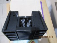
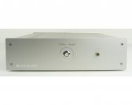
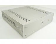
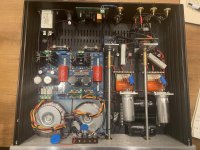
I recently have built a power amp based on Hypex NC122MP board. I bought a Ghent Audio connection kit, and it went quite smoothly. The only issue I have is a humming noise in both speakers, not very strong, barely perceptible from the listening position, which seems to be specifically related to the input connection.

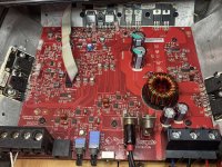
For reference, in the NC122MP, the inputs are mapped to the following pins of the J4 H-Box connector:
- for channel 1:
--- pin J4.1 - inverting signal ("-")
--- pin J4.2 - non-inverting signal ("+")
--- pin J4.3 - ground
- for channel 2:
--- pin J4.16 - inverting signal ("-")
--- pin J4.15 - non-inverting signal ("+")
--- pin J4.14 - ground
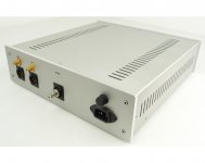
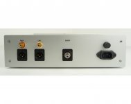
I use the Ghent Audio h-box connector to attach shielded 3-wire input cables, connected to the RCA sockets. "+" goes to RCA pin. "-" and "ground are soldered together, attached to RCA sleeve, and are grounded tot he chassis.

Here is what happens:

Case 1: Amplifier powered on, connected to 2 speakers, all wires disconnected from the J4 H-box -- dead silent
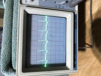
Case 2: Amplifier powered on, connected to 2 speakers, input wires, connected to the RCA input sockets, with sleeve grounded, are connected to J4 H-box, nothing plugged into RCA input sockets -- humming noise
Case 3: Amplifier powered on, connected to 2 speakers, input wires, connected to the RCA input sockets, with sleeve grounded, are connected to J4 H-box, a source (network streamer with volume control) is plugged into RCA input sockets -- very slight humming noise, I really need to put my ear to the speaker
Case 4: Amplifier powered on, connected to 2 speakers, all wires disconnected from the J4 H-box; 1 single wire, 2-3 cm long, attached with a JST connector to J4.2 (channel 1, non-inverting signal, or "+") - same humming noise in channel 1 speaker as in case 2.

Basically, looks like
- powered on, connected to speakers, but with nothing attached to input pins, the amp is dead silent (except the usual slight pop when powering the amp on or off).
- attaching anything at all to "+" signal inputs provokes humming in the corresponding speaker.
- attaching an actual source on the other end of the connection cable does not stop, but attenuates the humming.

Any advice on possible causes, or troubleshooting hints would be much appreciated. Thanks.

Attachments

  • 20201225_132523.jpg
    20201225_132523.jpg
    1,014.3 KB · Views: 459

Variable speed reel to reel machine

Hello

I have some reel to reel tapes from when my siblings and I exchanged conversations with our dad who was on a course in Philadelphia. These are from the mid 60s.

One of them plays fine on the machine that I have, but 3 of them sound like chipmunks talking.

Would this problem be solved with a reel to reel machine that could vary the playback speed?

If so, where could I find someone who had one?

I found this forum and was hoping that this would be a good place to start my search.

Thanks, in advance, for you help with this.

Grant

what connectors for 12VDC/5A

Hello everyone,

I'm looking for wire-to-wire and wire-to-chassis connectors for max 50V/5A DC. Use cases are 5V and 12V DC, 2-3A. Goals are

  • connect a DC12V power module to a wire coming out of a device.
  • connect a DC12V power module to a socket on back of a chassis.
Obviously the power module output should be female to be safe from accidental short-circuit when hanging around, and so the male parts should be on the device side.

I don't want any of those coaxial cheap models like on wall-PSU, they are unstable, cheap, and voltage drop is just too high. 4mm banana not wanted, that should look professional, not "lab on an excursion".

Best would be with some lock-in mechanism, preferably by rotation or screw, not by plastic clips that break after 5 manipulations. Should be either solderable and by screws, and preferably some multi-vendor standard that I would find at Distrelec, Mouser or the other suspects.

Hints welcome 🙂
Charles

Teradak 2.7 8xTDA1543 clicks and pops

Hi, I recently bought a Teradak 2.7D NOS and it has clicks and pops problems on both channels. I removed all TDA1543 and tested them individually one by one but the click is always there. The problem happens with all the interfaces, USB, Toslink and SPDIF. I suspect that it can depend from Jitter also if I cannot explain how I can have it when I'm connected to USB as Tenor7022 and WM8055 are using same 12Mhz 1ppm oscillator.
Someone else had the same experience and could help me to solve this noisy issue ?

For Sale: EICO ST70 output and power transformers

EICO ST70; 2 output transformers and 1 power transformer set.

Specs:
OPT: Primary Impedance: 6.6K ohm (no UL tap, used 7591 in Pentode)
Secondary taps: 4, 8, 16 ohm
Each good for 40 watts

PT: Primary: 115VAC
Secondaries: A bunch, never considered. Thrown in as an extra.

All measured OK for resistance/continuity all primaries and secondaries. No open or shorted circuits.

All end bells pulled and glass beaded -ready for paint. Original hardware included in a bag.

Originally acquired for the OPTs for a P-P 300B project for an Oregon Triode Society build.

In John Atwood’s testing and measurement of vintage output transformers, these EICO ST70 OPTs were only bettered in BW and quality by Harmon Kardon Citation II transformers.

$130 shipped -CONUS only (they are heavy)

Looking for TN2002 transistor for 400a and 4000 meter boards

I have a Threshold 400a with a malfunctioning meter board which I thought I'd rebuild since it's out. There are 2 transistor marked TN2002 which I can not find. I've gone to Alltransistor.com trying to find a replacement but no luck.

Would anyone know a substitute transistor?

Thanks,

Eric M.


**** OK, tried attacking from other direction. Schematic labels transistor as A42 (a Threshold house #) but you people here already assigned a part number of MPSA42 in the post

A42 in Threshold amp

If I missed anything, please post up.
Thanks

12B4 Preamp hum

Since building a common cathode 12B4 preamp it has been plagued with 60Hz hum. The hum is constant through the speakers regardless of volume. The hum is faint, only noticeable when no music is playing, very annoying though!

I can hear the toroid transformer hum if I put my head very close to the transformers themselves. I don't think it is DC on the mains as I understand that DC on the mains doesn't affect small toroid transformers like mine very much.

Amp is star grounded with the common star point leading back to a bridge recto || resistor || cap isolator which then goes to chassis ground.


What I've tried:
- different 12B4 tubes
- shielded wire for all signal wires
- adding foam insulation under the toroid transformers themselves


Schematic:
Forgot to draw another stage of RC filtering, 270R with a 30uF to ground. Input selector for three inputs. Mute circuit to short the output to ground for 30 seconds upon start up. IEC filter for the 120V mains.
The PSU is the PS-1
PS-1 Solid-State Regulator Kit

Attachments

  • 65DF9C94-6A91-4538-B01B-649142EB0253.jpeg
    65DF9C94-6A91-4538-B01B-649142EB0253.jpeg
    736.3 KB · Views: 187
  • C77FB0B3-47A0-4AC9-B599-1FD48E722516.jpg
    C77FB0B3-47A0-4AC9-B599-1FD48E722516.jpg
    712.4 KB · Views: 185
  • 9E46A1A0-F0FD-4211-9FE7-DA540459B47C.jpg
    9E46A1A0-F0FD-4211-9FE7-DA540459B47C.jpg
    1 MB · Views: 179

Crossover Help

Hello all, i need some help from expert people about croossover design.
I have some normal hifi speakers model jbl l830. They are monitors/bookshelf.
Since i m in lockdown at home because i m positive to covid and i have some sb acoustics drivers around for serveral months (plan to build a good speaker) i start to look at jbl croossover and to my understanding i tried to swap the original jbl tweeter for my sb acoustics satori tw29rn-b-4. I got a mdf base for the sbacoustics tweeter and put it on top.It sounds ok and i like the sound but i see jbl tweeter are only 3.3 ohm.
I attached the jbl schematic. I appreciate if someone with experience could look at it and see if the satori is working ok with that type of croossover or if is needed to change some values. I have some resistors laying around and also some caps and coils. I m using the orginal croossover but with better parts, better caps and a better coil in woofer.
Thks[emoji846]

Screenshot_20210203-113850_Drive.jpg20210203_123619.jpg
View attachment 918329
View attachment 918330View attachment 918331

Horn-based two-way suggestions?

I built a pair of Econowaves four years ago with Dayton Audio D250P-8 1" Polyimide CDs bolted to Dayton Audio H6512 6-1/2" x 12" waveguides, using the Large Advent woofers in LA cabinets. I use the Zilch-designed XO. I like 'em! These days most of my listening is with a pair of Omega alnico speakers, but I've always wanted to "scale up" the Econowaves. I like horns for their dynamic impact, two-ways for their simple crossovers, and high sensitivity (95dB+) because I like SET amps.

How about the FaitalPRO LTH142 1.4" 60 x 50 Elliptical Tractrix Horn with . . . ? Lots of blanks to be filled in!

More voltage on screen than grid?

More voltage on screen than plate?

Just finished a new build based on this design. I used some unused 3.5k ohm transformers I had from a previous kit build which indicated a 46% UL tap. When testing voltages I'm seeing 331 B+, 320 at the plates but 326 at the screen. I'm assuming that I probably need a larger value resistor than the 100 ohm I've got in there based on the triode set-up of the design. Any recommendation on voltage I should be seeing at the screen and/or a resistor size I should be shooting for? I'd rather start off with some intelligently sourced ideas than keep swapping resistors in a cramped chassis. Thanks all!

6V6 Single Ended Stereo Hi-Fi Advices

Hi everyone! I'm an EE, but pretty newbie to DIY vacuum amplifiers. After weeks of researches on books, forums, and youtube videos, I've some idea of how hi-fi schematics work. I'm now trying to finalize a schematic decision in order to order parts that I need. However, I've got few questions.

First of all, I can hear you all asking "What do you want?". Here's what I want:
  • 6V6 SE
  • 8-10 Watts Output
  • Ultra-Linear (Maybe switched triode)
  • 12AX7 preamp
  • Diode rectification
  • Mid-level volume operation
  • Input will be line level (from pc or turntable with line level amp)
  • Pure-natural sound

Now, here are my questions.

Power Supply
I'm planning to use a transformer with no tap (because it's cheaper) and diode bridge. I know I can use higher capacitance values w.r.t. tube rectifier and this will improve my ripple rejection. However, is it ok if I use no choke in that case (they are expensive)?

Preamp Tube Selection
In preamp stage, I've read that 12AU7 is not as linear as 12AX7. That's why I'm preferring 12AX7 even though it has unnecessary amount of gain for me. Would you suggest using 12AT7 or should I go with 12AX7?

Preamp Design
I've seen something as 4S universal preamp for 12A*7. Many schematics around the web uses a variation of this preamp. However, I've read somewhere that it is a "fiasco" and there shall not be something called universal preamp. I've seen many references on how to design output stage, but I don't really know how to design preamp stage. What do you think about this 4S Universal Preamp? What should I consider for an 12AX7 preamp?
Here is the schematic I'm talking about.
4S-Universal-Tube-Preamplifier-Schematic.png


Negative Feedback
I've seen some very good sounding design that has no NFB. Would you suggest NFB or not? Why?

Some Designs I've Found
MW_Schematic_amp.jpg

This one also uses the "4S Universal Preamp"
An externally hosted image should be here but it was not working when we last tested it.

This one is from kleydejong of tdpri.com. I'm planning to build something like this, maybe without NFB. What do you think about this?

Thank you! 🙂

Noobie anode load line question

I'm trying to learn anode and cathode load line plotting Google style and have one small question... Some of the tutorials tell you to sum the value of the cathode and plate resistors in computing the current, and other tutorials neglect to even mention this and just tell you to use the value of the plate resistor. It doesn't seem to matter much with maybe a 12AX7 where the cathode resistor might be 1K and plate 100K, thats only a 1% difference.

Is it best practice to routinely just sum Rk and Rp so the total current across the tube is accounted for?

RF P200.2 No Sound, not in protect?

No sound until I back the power supply down to about 11.5V. Then it's faint but changes with the gain. I purchased Perry's manual and have been reading and re-reading the power supply and x94 operations. Some things point towards the transformer. I was also considering the voltage regulators. Nothing looks burnt and no shorts on the outputs but no voltage, either. 26V AC between center legs of Q9 an Q13(right of power terminal). 12.4V DC on the RCA shields. I have some higher than I would expect voltage on TL494 Pin 8, 11, & 12: 24.8V DC. Here are the other DC measurements:

Pin 1: 2.15
Pin 2: 2.45
Pin 3: .0076
Pin 4: .0013
Pin 5: 1.5
Pin 6: 3.4
Pin 7: 0
Pin 8: 24.8
Pin 9: 10
Pin 10: 10
Pin 11: 24.8
Pin 12: 24.8
Pin 13: 5
Pin 14: 5
Pin 15: 5
Pin 16: 0

Attachments

  • IMG_1443.JPG
    IMG_1443.JPG
    818.8 KB · Views: 67

very large DC offset on a LM3886

( SOLVED) I was thinking about going active speakers so I thought of making some small multichannel power amps using the LM3886. Used the schematics for here:
https://www.circuitbasics.com/wp-co...-an-LM3886-Circuit-Schematic-with-Diode-2.png

Just changed a few things to use components I have around. Like 10µ in the input and filtering as I have enough of those. I use a UPC1237 for protection so I only put a 30k resistor at pin 8 (mute). PSU is +/- 23V. And I added a 270p between the positive and negative input.

But when I power these up I have a DC offset of 8-9 VOLTS!

First I tought of a bad connection or wrong components. But I now made a second one (without the UPC1237) and I have identically the same thing. Any ideas where to check because this is getting seriously on my nerves.

Multiplier Regulation

I'm building a Millenium 5-20 Valve amplifier but only have a 115V output transformer.

The transformer is rated at 220VA so should be good for 115V at about 2A.

My amplifier requires 450VDC at 250mA.

I'm using 1N4007 and 220uF caps in the multiplier.

Why is the voltage regulation so poor ?

Testing the multiplier with a 70W load I get the desired 415VDC but it is still over 500VDC off load.

USB (UAC1) to I2S Slave

I'm looking for a budget sensitive way of making a USB to I2S device, but where it's the i2s slave. I'd normally go for a SiLabs CP2615 for USB to I2S, but it is only capable of master.

I only need 2 channels in and out, at 24/48 only.

I've looked at the Teensy Audio project, but it seems to be limited to 16 bit (at the moment). I've also looked into the XMOS XUF208, which is capable but a somewhat complicated toolchain and a little overkill for a simple task.

Would appreciate any thoughts or pointers 🙂

  • Locked
FS@cost: Cordell SuperGainclone w/Klever Klipper. One fully assembled, one bare PCB

---SOLD---

I was curious about Bob Cordell's Super GainClone and Klever Klipper so when I came across a set of boards that allowed me to easily test both, I jumped at the opportunity. You can see my measurements here: Review: Cordell Super GainClone & Super GainClone with Klever Klipper – Neurochrome

The Super GainClone performs pretty well, actually. It offers slightly lower THD+N than the 'naked' LM3886 at higher power levels. I wasn't as impressed by the Klever Klipper, but each to their own. This board allows you to disable the Klever Klipper by removing a jumper.

You can find the BOM for the circuit in Post #1 of this thread: Bob Cordell's Super Gain Clone PCB (LM3886) and a stripped-down version: Compact3886

Anyway. I have two boards as shown in attached image. One is fully assembled. The other one is ready for you to assemble. What you see is what you get.

I have gotten my technical curiosity satisfied so I have no further use for these. I'm selling them for the cost of parts, so $59 USD + shipping.

I ship world-wide and can take payment by credit card or PayPal. If you're in Canada, I can take payment by eTransfer as well.

Shipping by Canada Post to the US is $10 for standard airmail. $15 if you'd like tracking as well. Canada Post delivers in about 3-6 weeks these days. Shipping to Europe and Canada is ~$5 more.
I get excellent rates with FedEx and UPS and can get the box to your door in a few days for about $20-25 (US, Canada) and more like $30 for the EU.

Above shipping rates are estimates. Please contact me by PM or email (add @neurochrome.com to my user ID) if you're interested in these. Include your shipping address and phone number (needed for customs) and I will get an accurate shipping quote to you.

Cheers! :cheers:

Tom

Attachments

  • SuperGC.jpg
    SuperGC.jpg
    357.7 KB · Views: 231

What does this PSU feature do?

Hi everyone!

I recently got an old 1970s regulated power supply unit off of ebay. I´ve tried looking for info on the manufaturer and had no success...


I want to ask you if anyone knows what is meant with the resistor connection thats printed on the positive outputs labeled V and I. This might be a newbie question, but i haven't had experience with this kind of PSU.

Thank you for your help!
DSC_0695.JPG

Nikko Alpha 230 - Parts where to go

Hi
My original Alpha 230 is getting a bit cranky so it is probably time to do a recap before something craps out.
Does anyone have a good parts list or parts source recommendation for this unit?
I have a copy of the digital copy of the Service Manual, but the parts list is a bit of an eye test for me.
Looking for any sage advice to get going.

Thanks!

My Beta unit is probably also going on the bench once I get the Alpha back

New sub design? Constricted Transflex, simple build (series tuned 6th order)

It is affordable, is extremely simple to build, small, and according to HR simulations the output looks very respectable. Group delay and excursion also look reasonable with the $50 SWE-10S4 drivers that i used in the sims.. .

Tinkering around with Hornresponse a while back i came up with this design... I never built one (and i probably never will because i have already moved on to other ideas that i want to pursue) but i thought i would post this on DIYaudio to see if anyone finds it interesting or useful .. I was also curious to see what the big-brained subwoofer gurus had to say, be it good or bad ..

I refer to it as a constricted transflex, but its like a tapped horn that is squeezed down in the middle, and it is also like a pipe-resonance mode based (instead of helmholtz mode) series tuned 6th order bandpass box ..
The drivers need to have an FS close to FB, along with tight suspensions and strong motors to work properly in this box...

I found two different ways of simulating it in HR, one utilizes the compression chamber function, and the other doesn't , but as far as i can tell both sim methods are valid and produce a very similar response and output ... I will post both sets of HR inputs.

As you can see one of the drivers can be physically mounted in reverse and the phase flipped to make this a push-pull (actually push-push right?) to cancel some distortion.. I know the "PP" feature has been something that some folks on this site have been using lately in other designs, so call me trendy 😛 ...

According to sims two of these cabinets (combined total of 200 liters) can handle 1000 watts without pushing the 10S4 drivers past their excursion ratings of 10mm one way, and output should be just under 130db with solid response all the way down to 40hz in halfspace .. Seems great for 2 small boxes that could be built in less than a day, using only 200 dollars worth of drivers total !

In a car or a truck (1/8th space or .5pi) the output is pretty obscene with one cabinet making 135db with only 500 watts input power , but of course only down to 40hz which is fine for much music but not all (depends on your personal preferences right?)

I didn't show any cabinet bracing in the sketch but its easy enough to improvise those ...

The response graphs remind me of some of the old MTL-1X Manifold-horn cabinets that EV used to make for dual 18" woofers, which is not suprising because those were also series tuned 6th order bandpass boxes, only much larger ...

I am looking forward to hearing your thoughts and reading you comments regarding this design. 🙂

Attachments

  • Constricted-Transflex--with additional measurements.JPG
    Constricted-Transflex--with additional measurements.JPG
    35.1 KB · Views: 8,389
  • 2cabs(200L-total_1000w).JPG
    2cabs(200L-total_1000w).JPG
    48.7 KB · Views: 8,236
  • Alpine-SWE-10S4-Parameters.jpg
    Alpine-SWE-10S4-Parameters.jpg
    52.6 KB · Views: 7,925
  • 100L-Constricted-Transflex-Inputs-fish.JPG
    100L-Constricted-Transflex-Inputs-fish.JPG
    67.8 KB · Views: 7,853
  • 100L-Constricted-Transflex-Inputs-CHAMBERED.JPG
    100L-Constricted-Transflex-Inputs-CHAMBERED.JPG
    61.2 KB · Views: 7,800

Decoupled rectifiers- yes or no?

What are your subjective experience with decoupling the rectifier diodes? I dont mean a snubber across the secondary but rather a cap across each diode. With 1nf mkt caps across the silicon diodes im using to feed my 1875 amp, i notice a significant difference in the sound. With the decoupling in place the sound is heavier, darker (less treble energy) and the sound stage more closed in. Without the decoupling i get most of the lost ambience back but knowing that much of its sound character could be due to the unfiltered harmonics of the diodes i cannot decide which configuration is a superior

Using higher ripple low impedance Panasonic FM instead of Nichicon KZ

Hi

Regarding Technics SU-3500 I was thinking to use some higher ripple low impedance Panasonic FMs instead of Nichicon KZ which have poor ripple for the voltage regulator .

Is about four 220uf caps connected to the voltage regulators .

Those voltage regulators are 2SD390A I posted a photo . Those 220UF caps are connected to TR501 506

Panasonic FM have very low ESR and the ripple is almost triple compared to Nichicon KZs. There is any chance that this ultra low ESR and huge ripple might cause the regulators to malfunction or ultra heat ?.

Attachments

  • 345.jpg
    345.jpg
    526.8 KB · Views: 1,028

Eiki LC-XA20 Ballast bypass not working

I am trying to bypass the ballast in this projector I got for free so I can LED mod it. I have found the wires going from the ballast to the main board. I found the pin for the transmit optocoupler, and I shorted it to ground. Before I did this, the fan would ramp up and down 3 times over the span of a minute and then flash the power led. After I did this mod, it now goes green for a few seconds then cuts to the flashing red. If I shine a light, I can see the eiki boot logo until it realizes that there is no lamp. I found the thermistor and I heated it and saw the resistance dropped to 0 ohms, so I tried shorting the pins for it but it had no effect.

Using SPL & Impedance graphs to generate ZMA & FRD files for crossover modeling

Using SPL & Impedance graphs to generate ZMA & FRD files for crossover modeling

Is there a way to use the data in freq. response and impedance graphs to generate FRD and ZMA files?

I've heard the term 'graph grabbers' but I don't know where to find them, or how to use them. I assume this is a software to interoperate graphs somehow? Any pointers greatly appreciated! 🙂🙂🙂


Hi, I'm new here so correct me if I'm wrong but...
As I understand it:
FRD files = Frequency Response data
ZMA files = Impedance data
Correct?


I need both ZMA and FRD files to use crossover modeling software however...


Manufacturers often share Frequency Response data and Impedance data as PDFs or PNGs but (with the exception of Dayton Audio) rarely FRD and ZMA files.


My question is: Is there a way to use the data in freq. response and impedance graphs to generate FRD and ZMA files?

It should be possible, all the data is there... just in the wrong format.​


Dayton are great but I don't want to be reliant Dayton components solely for the reason they're the only drivers I can model with.


Thanks in advance <3

Tube amp PS caps

Hello all,
Grandkids are getting old, so I'll finally have some time to get back to the bench.
Will be building one of two topologies, both loosely based on Decware's SE84 series.
One is 6922-IT-EL84 ( TS ).
the other is EF86(TS), RC coupled to EL84 ( TS ).
the power supply will be identical for either.
Config will be C-L-C-L-C ( for power tubes ), tube rectified. Would like to keep the first rectifier under 8 uf for various reasons. Which brings me to my question.
All parts used ( have everything in hand ) will be top notch. Years ago when I modded the crap out of my SE84CS I swapped all the lytics out for ASC motor runs and loved what they did. the last two caps will be ASC, which brings me to the first cap after the rectifier.

I've got a bunch of ASC 15uf X386 caps, so a pr in series will get me at 7.5 uf for the first cap. My question to you guys.

Should I keep that cap as an ASC motor run cap, or would a higher quality ( say Mundorf ) foil cap be better sonically in that position ? I'm trying to squeeze as much out of the circuit as I can, and don't want to limit it because of one cap.

So, keep the ASC in that first position or look for a true film/foil?
Aas always, thanks in advance for your advice,

Cheers, and be safe,

Crazy Bill

Hammond 126B Frequency Response and More...

Hello All,
Awhile back I bought a pair of these for a 211 project. I was somewhat skeptical because of the price ($74USD each), but I took a chance and bought them based on a few positive comments I found when researching interstage transformers.

As usual, there are a lot of opinions floating around but not much data (or measurements) to show you how the device performs.

I built a test circuit (gain of 100) to give me approximately 300VP-P to see how the 126B would perform. Test circuit consists of SRPP 6SN7GT / 6BX7GT with 6BX7GT sections paralleled, running 30mA's thru the 126B.
6BX7GT Operating Parameters:
B+: 275VDC
Voltage across tube: 247.5VDC
5VDC loss across 126B
22.5VDC bias
750 Ohm cathode resistor, bypassed with 100uF cap

I terminated the secondary with 100pF and 560kOhm for testing. I also removed the 560kOhm resistor and the frequency response was still flat with no peaks or ringing.

Attached are a few measurements.

Attachments

  • Hammond 126B_6BX7GT_100pF_560k_28VRMS_Analyzer Panel.jpg
    Hammond 126B_6BX7GT_100pF_560k_28VRMS_Analyzer Panel.jpg
    116.5 KB · Views: 911
  • Hammond 126B_6BX7GT_100pF_560k_28VRMS_Frequency Response.jpg
    Hammond 126B_6BX7GT_100pF_560k_28VRMS_Frequency Response.jpg
    88.2 KB · Views: 913
  • Hammond 126B_6BX7GT_100pF_560k_100VRMS_Analyzer Panel.jpg
    Hammond 126B_6BX7GT_100pF_560k_100VRMS_Analyzer Panel.jpg
    117.9 KB · Views: 892
  • Hammond 126B_6BX7GT_100pF_560k_100VRMS_Frequency Response.jpg
    Hammond 126B_6BX7GT_100pF_560k_100VRMS_Frequency Response.jpg
    87.5 KB · Views: 902

Newbie question Re heat sinks

I've always wanted to make my own amplifier but I've also been hesitant to do so.
I've not even started the little chip amp project I bought the makings for.
but I find I need a new amplifier for subwoofer duties as the one I have been using just died.

I've gone back to the ESP website and reread the project I was thinking about. Rod Elliots MOSFET high power amp the Project 101.

I have a couple of big toroids here as a starting point.
2 * 500 VA
Hoping to find a mentor locally but that has been hard lately with lockdown etc.

Rod E's page does say they if making the high power version you need really big heat sinks and active cooling. Is it possible tho to have heat sinks that are too large?
I have come into the possession of a large heat sink.
It's 3700grams, multi finned, 270mm tall, 180mm wide and 75mm deep

I think it came from a rooftop solar array originally, the donor never said but he's a solar installer
Adequate?
Too big?

Thyratron rectifier 2

I have some G4S10 thyratrons. Have been playing with ideas such as guitar effects and synth use, but why not rectification. The thyratron rectifiers I've seen are using the grids to control the output, kinda half wave PWM of sorts. But I just want to use them as rectifiers, no fancy control.
I see on one thread here that the grids should go to the power transformer, leave plates floating, and that's it. But surely that can't be right? The grids are only to turn the device on. As a rectifier it should be on the whole time.
So is it not right to connect the grid to the cathode?
Also, I see claims of 'choke input only' but thyratron's magnificance is their incredible pulse current durability, is it not? So I'd think a cap input supply is no prob...?
Any tips before I wire this up? Thanks.

Attachments

  • thyratron_rect.PNG
    thyratron_rect.PNG
    33.5 KB · Views: 559
  • G4S10data.PNG
    G4S10data.PNG
    134.2 KB · Views: 510
Projects by fanatics, for fanatics
Get answers and advice for everyone wanting to learn the art of audio.
Join the Community
507,812
Members
7,889,480
Messages

Filter

Forum Statistics

Threads
406,300
Messages
7,889,480
Members
507,812
Latest member
MwanyamakiJr