Since building a common cathode 12B4 preamp it has been plagued with 60Hz hum. The hum is constant through the speakers regardless of volume. The hum is faint, only noticeable when no music is playing, very annoying though!
I can hear the toroid transformer hum if I put my head very close to the transformers themselves. I don't think it is DC on the mains as I understand that DC on the mains doesn't affect small toroid transformers like mine very much.
Amp is star grounded with the common star point leading back to a bridge recto || resistor || cap isolator which then goes to chassis ground.
What I've tried:
- different 12B4 tubes
- shielded wire for all signal wires
- adding foam insulation under the toroid transformers themselves
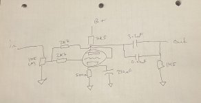
Schematic:
Forgot to draw another stage of RC filtering, 270R with a 30uF to ground. Input selector for three inputs. Mute circuit to short the output to ground for 30 seconds upon start up. IEC filter for the 120V mains.
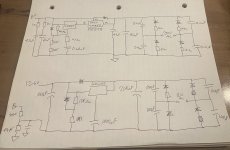
The PSU is the PS-1
PS-1 Solid-State Regulator Kit
I can hear the toroid transformer hum if I put my head very close to the transformers themselves. I don't think it is DC on the mains as I understand that DC on the mains doesn't affect small toroid transformers like mine very much.
Amp is star grounded with the common star point leading back to a bridge recto || resistor || cap isolator which then goes to chassis ground.
What I've tried:
- different 12B4 tubes
- shielded wire for all signal wires
- adding foam insulation under the toroid transformers themselves
Schematic:
Forgot to draw another stage of RC filtering, 270R with a 30uF to ground. Input selector for three inputs. Mute circuit to short the output to ground for 30 seconds upon start up. IEC filter for the 120V mains.
The PSU is the PS-1
PS-1 Solid-State Regulator Kit
Attachments
Last edited:
Perhaps . . .
You have created a ground loop with B+
You have created a signal ground loop.
You have ripple on B+ or filament, even though you are regulating them.
You also may have a ground loop with either the signal source to preamp,
or you may have a ground loop from the preamp to the power amp.
Too much gain of the power amp, can amplify a small amount of hum from the signal source or the preamp.
Maybe, but I have brought all grounds to a single star point, this point then goes to the chassis through a bridge recto || resistor || cap.You have created a ground loop with B+
Maybe, but I have brought all grounds to a single star point, this point then goes to the chassis through a bridge recto || resistor || cap.You have created a signal ground loop.
Maybe, I have 150uF of filtering before and after the B+ regulator. Then an addational 33uF localized at the B+ by the tubes.You have ripple on B+ or filament, even though you are regulating them.
The heaters have 20,000uF of filtering prior to the regulator and 1000uF of filter after the regulator.
This occurs with nothing connected to the preamps inputs. I am feeding a NAD214 which uses a 2 prong AC cable. The preamp and NAD214 are connected via a grounded RCA cable.You also may have a ground loop with either the signal source to preamp,
or you may have a ground loop from the preamp to the power amp.
This occurs with the volume at 0, no signal.Too much gain of the power amp, can amplify a small amount of hum from the signal source or the preamp.
Ok.
Input RCA connector: Isolate the connector return from the chassis. Connect the return, and volume control return to the bottom of the tube's self bias RC network. Then connect the bottom of the bias network to the star ground (do not connect the RCA connector return directly to the star ground; and do not connect the volume control return directly to the star ground).
Keep the signal return currents only going to the cathode circuit; do not let them go directly to the star ground (that is to create a local current loop, not a larger current loop).
B+: Connect the bridge return (-) to the first filter cap.
Do not connect the bridge return directly to the star ground.
Then, connect from the first filter cap - to the regulator return. Then connect the regulator return to the star ground.
You do not want the charge current from the bridge to go directly to the star ground.
Keep those large(r) currents from going directly to the star ground.
That creates a local current loop, not a larger area and length current loop.
Without looking at the rest of the circuit, I hope you are starting to see the difference between a local loop, versus a larger loop.
Wires are not just a wire.
A short wire is one thing, a longer wire is worse.
Wires are a resistor, even if they are 10milliOhms. 200mAmp of transient capacitor charge current is 2mV of loop voltage. A 12B4 may amplify that 2mv to be 10mV.
The peak transient charge current of the first cap, may be 5x or 10x the DC output current of the supply. With that large peak transient current, even a milliOhm of wire resistance is better than 10milliOhms.
A sensitive power amp will produce hum in the loudspeaker, even if the hum is small.
Even if you use a regulator chip, that means the voltage out from the chip + to the chip - has extremely low ripple, but if the return wire has the signal from the first cap - charge current, then both the + and the - from the chip are 'jumping' up and down by that first cap return voltage. And that becomes a Hum 'signal'.
The very large 22000uF caps in the filament circuit have large transient currents. You have to create a local loop to return that current, do not let that transient current go all the way to the star ground.
Wires are not only resistors, they are inductors.
Even small inductance that has the fast rise transient first capacitor current, will create a high frequency ground loop.
A single star point, with all returns going to it, will create ground loops.
Local ground loops are better.
After the large transient currents have been contained in local ground loops, then the returns can go to the star ground.
Last edited:
Power supplies of one device (preamp) and another device (power amp) can have leakage current from the hot an neutral mains wires, versus to the mains ground.
But the leakage current and voltage of one of those two, can be different than the leakage current and voltage of the other one of those two.
Guess what? Those differences cause a current in the shield wire of the RCA to RCA cable.
That current induces a voltage into the center wire of the RCA to RCA cable.
That can cause hum and/or noise at the power amp input.
Just another kind of ground loop.
Do the 2 wire power plugs have one wide lug and one narrower lug?
If the lugs are equal width, you can try turning one the other way when you plug it in.
that may reduce or increase the hum.
astouffer,
Correct.
ChrisM91,
We need to verify if the hum is primarily 60Hz or 120 Hz.
60Hz hum may very well be a ground loop from the preamp to the power amp, due to the leakage currents of the power mains to both the preamp and power amp, versus the difference of those two leakages.
It would be nice to know what the gain of the power amp is with its volume control turned up full, and the amplitude of the hum at the output terminals of the power amp.
Last edited:
Ok 6A3sUMMER a bit more info! Thanks for all the help thus far 😀
I am attaching a sound sample of the hum. Recorded with my iPhone right next to one of the 6.5" speakers. From my listening position 8' away I can hear the hum clearly at idle.
The 12B4 preamp has a gain of 6.5 (16 dB).
NAD214 preamp is 80W into 8R with an input sensitivity. I believ that works out to be a gain of 28.1 (29dB). The power amp two prong plug only fits on way by the way.
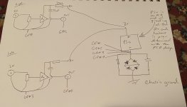
I now have the grounding set up as such:
All the PSU grounds on the PCB are connected via the traces set out by the designer, then a single wire goes to chassis ground through a bridge recto || resistor || cap.
The audio grounds all go to the same chassis ground via their own wires. The audio grounds include the final RC filtering, 270R with a 30uF to ground. One RC filter for each channel.
I have not yet amalgamated them as suggested (then run a single wire back to the chassis).
I am attaching a sound sample of the hum. Recorded with my iPhone right next to one of the 6.5" speakers. From my listening position 8' away I can hear the hum clearly at idle.
The 12B4 preamp has a gain of 6.5 (16 dB).
NAD214 preamp is 80W into 8R with an input sensitivity. I believ that works out to be a gain of 28.1 (29dB). The power amp two prong plug only fits on way by the way.
I now have the grounding set up as such:
All the PSU grounds on the PCB are connected via the traces set out by the designer, then a single wire goes to chassis ground through a bridge recto || resistor || cap.
The audio grounds all go to the same chassis ground via their own wires. The audio grounds include the final RC filtering, 270R with a 30uF to ground. One RC filter for each channel.
I have not yet amalgamated them as suggested (then run a single wire back to the chassis).
Attachments
Last edited:
There is at least one more, the 6AH4 linestage I helped my son build hummed a wee bit, and it increased with volume setting. Clipping the plate everything was mounted to to signal ground cured it. DC filaments, big-C LC filter, active loads, and isolated RCA plugs.
Same with the last amp; ground secondary of the OPT reduced it, and tying plate to ground eliminated it.
cheers,
Douglas
Same with the last amp; ground secondary of the OPT reduced it, and tying plate to ground eliminated it.
cheers,
Douglas
What setting is the NAD214 volume control set to?
7:00, 9:00, 12:00, 2:00, or where?
NAD amplifiers are solid state, and usually have extra large gain.
Too much gain, too high of a volume control setting, might result in a very small amount of hum from the 12B4 preamp, that goes through the NAD214 set to high gain, causes it sounding like loud hum in the speakers.
What setting is the NAD214 volume control set to?
7:00, 9:00, 12:00, 2:00, or where?
NAD amplifiers are solid state, and usually have extra large gain.
Too much gain, too high of a volume control setting, might result in a very small amount of hum from the 12B4 preamp, that goes through the NAD214 set to high gain, causes it sounding like loud hum in the speakers.
The NAD power amp is running full out! There is no gain/volume control. The only thing to control the volume of my overall system is the volume control at the very beginning of the 12B4 preamp.
Could this be my issue??? Good news is I am working on building a F6 power amp in the coming weeks.
Today I am going to redo the grounding scheme to the format attached here. Also going to try stacking the toroids, so that the transformer closest to the tubes is moved away (and stacked on top of the other) from the audio path.
Attachments
Good news! 😀
Hum is gone
I implemented the grounding scheme in my post above which was a lot of work but well worth it in the end. I tested the amp and it was definitely quieter.
Then I moved the HV toroid that was closest to the tubes. I got a long bolt and stacked the HV transformer on top of the LV transformer. This did the trick in removing the 60Hz hum.
So the hum was two parts; a poor grounding scheme and the audio circuit picking up the transformers field.
Thanks 6A3sUMMER for all the advice
- Home
- Amplifiers
- Tubes / Valves
- 12B4 Preamp hum