Hi, I recently bought a Teradak 2.7D NOS and it has clicks and pops problems on both channels. I removed all TDA1543 and tested them individually one by one but the click is always there. The problem happens with all the interfaces, USB, Toslink and SPDIF. I suspect that it can depend from Jitter also if I cannot explain how I can have it when I'm connected to USB as Tenor7022 and WM8055 are using same 12Mhz 1ppm oscillator.
Someone else had the same experience and could help me to solve this noisy issue ?
Someone else had the same experience and could help me to solve this noisy issue ?
From a few pics of the pcb out on the web, looks like its probably not too hard to take the board out and sketch up a schematic of the circuit. With that and maybe a scope, in the worst case maybe a logic analyzer, it should be possible to figure out what's going on and probably fix it. Short of that, a reasonable first step might be to check all the power supply voltages and waveforms. Also maybe inspect all solder joints, etc. Just kind of go through it looking for any easy to find problems.
Last edited:
Dear Mark thank you for your answer,
for the moment I've checked and revised all the solder joints, checked with scope the clock and power voltage but they seems to be really stable. I can't understand from what it can depend so I hope that someone else that had same problems could help me.
for the moment I've checked and revised all the solder joints, checked with scope the clock and power voltage but they seems to be really stable. I can't understand from what it can depend so I hope that someone else that had same problems could help me.
I've identified the problem, it wasn't cause by TDA1543 nor from solderings. One of the two 74VHC74 was defective. The problem cannot be detected by Oscilloscope but as I studied how the flip flops were working I've identified also the two pads to bypass them, not before to have removed the thw vhc from the circuit. Now My Teradak is working very well and I'm not sure that I will repolace the two VHC74 because the sound seems very clear also without them and their noisy defect.
D-flip flops are often used for 'reclocking' or 'relatching' digital signals in dac so the signals are in exact time with the master clock. Typically, its done to reduce timing jitter. Don't know if that's what they are used for in your dac, nor what effect they might have on the sound.
Guess the most thorough approach might be to replace bad parts, then if you don't like the sound that way you could always modify the circuit back to the way you have it now. Hard to say much more without tracing out where the VHC74 output pins go. If they go the dac chip's clock inputs then seems most likely the D-FF's are being used in the way I described above.
Guess the most thorough approach might be to replace bad parts, then if you don't like the sound that way you could always modify the circuit back to the way you have it now. Hard to say much more without tracing out where the VHC74 output pins go. If they go the dac chip's clock inputs then seems most likely the D-FF's are being used in the way I described above.
I suppose, but i may also be wrong, that VHC74 were used to clean and square off more the clock signal without modifying the timing.
Below is the explanation of the operation of the VHC74 taken from its datasheet:
"The signal level applied to the D input is transferred to the Q output during the positive going transition of the CK pulse".
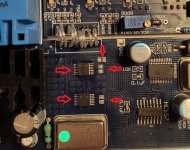
As specified before on the circuit there are three pads to bypass the two VHC74 (they must removed before to bypass them), this bypass will apply the clock directly from WM8805 (through HC157) to the TDA1543.
This bypass is quite similar to the one present on Chameleon to bypass upsampler board, you should know that I've also a Chameleon and I've removed this upsampling board because I prefer to have a pure NOS machine, it is a question of tastes and I know that not all love the sound of NOS dac.
Maybe that VHC could improve the sound but I can't notice important differences regarding jitter nor noise, so for the moment i will keep it without clock regeneration circuit exactly as I keep the Chameleon without the upsampling board.
On the other hand, if you look at the original project by kusonoki san, no reclocking circuit was foreseen.
Below is the explanation of the operation of the VHC74 taken from its datasheet:
"The signal level applied to the D input is transferred to the Q output during the positive going transition of the CK pulse".
As specified before on the circuit there are three pads to bypass the two VHC74 (they must removed before to bypass them), this bypass will apply the clock directly from WM8805 (through HC157) to the TDA1543.
This bypass is quite similar to the one present on Chameleon to bypass upsampler board, you should know that I've also a Chameleon and I've removed this upsampling board because I prefer to have a pure NOS machine, it is a question of tastes and I know that not all love the sound of NOS dac.
Maybe that VHC could improve the sound but I can't notice important differences regarding jitter nor noise, so for the moment i will keep it without clock regeneration circuit exactly as I keep the Chameleon without the upsampling board.
On the other hand, if you look at the original project by kusonoki san, no reclocking circuit was foreseen.
An externally hosted image should be here but it was not working when we last tested it.
The link to your attached image doesn't work from here. It often works better to attach an image file, which can be done in 'Advanced' edit mode.
In this moment I'm in advanced mode but I can strangely only put a link for the image.
Click with right mouse button on teh link and open it on a new tab, you should see the picture.
VHC74 — ImgBB
Click with right mouse button on teh link and open it on a new tab, you should see the picture.
VHC74 — ImgBB
😀 I haven't seen promptly the additional options 😀

Thank you Mark
P.S.
I'm not sure about my explanaition of the VHC74 circuit it could be also very approximate, so I hope that someone has a better understanding of this section can explain me better, also regarding TCXO frequency that doesn seems casual at all.
Thank you Mark
P.S.
I'm not sure about my explanaition of the VHC74 circuit it could be also very approximate, so I hope that someone has a better understanding of this section can explain me better, also regarding TCXO frequency that doesn seems casual at all.
- Home
- Source & Line
- Digital Source
- Teradak 2.7 8xTDA1543 clicks and pops