Alpine MRV-1505 weird power issue

I ran across an MRV-1505 that has a weird power-on issue.

I have never ran across one of these before. So, first thing I did was check the outputs, and power supply transistors. All good.

But, it did not power on.

I removed the power supply board, and saw a trace that had blown apart nearby the remote accessory connection. I patched that up, and attempted to power up the board with all the plugs disconnected.

The power supply came on and ran fine.

So I reconnected all the plugs, and once again, had no power. Not making any sense to me.

So, I noticed if I unplugged CH505 connector in the middle of the power amplifier board, the power supply would come on! Soon as I reconnected that connector, the power supply would shut down.

Then eventually after trying to test that connector for voltages, I plugged it back in and now the power supply is staying on...

what??

Anyone run into this before?

2nd order LPF for RS225-8

I've learned from this site that RS225-8 has been extensively used and highly respected. Can someone recommend a 2nd order crossover for the RS-225 in a 1.6 cf box ported box? I did find a couple of threads but I could not find something similar to what I was looking for. Unfortunately I don't have the time to become an expert the design tools out there and this is my first build in 20+ yrs.

Thanks in advance!

"Noisy" CDM 4/19

I have an odd problem with a CDM 4/19 coming from a Philips CD 320: it plays fine and never reject any disc, but when I press stop and the pick-up swing back to the centre, it hits the composite wall and produce a quite audible "tick" sound.

The pickup is supposed to have a rubber bumper to prevent that and it is still there, but i guess it hardened with age.

Anyone having a similar problem ?

Lampizator Amber Balanced KIT Tube DAC

Selling Lampizator Amber Balanced KIT Tube DAC.
I already have Lampizator Amber SE and I was planning to do Balanced version but changed my preamp to SE inputs so no need for DAC with balanced outputs anymore.

Here you have everything needed to build famous Lampizator Amber Balanced DAC.

Kit include:
1.Lampizator Amber Balanced Tube DAC Audio Stage with tubes included.
2.Lampizator transformer primary: 0-115-230V, secondary: 5V/2A, 10V/1A, 2x6.3V/1A, 180V/0.1A
2.DIYINHK ES9018K2M XMOS DSD DXD 384kHz USB DAC with Bit-perfect volume control and SPDIF input. Isolated DAC and LED PCB
3.Two Low Nosie Power Supply 5V and 3.3V
4.AK4113 Digital receiver board SPDIF to I2S converter software control + LCD (optional feature, not installed in original Amber)
5.DIYINHK i2S isolated boards

Price: 550 GBP ono + shipping+ PayPal fees

Attachments

  • 20210228_120654.jpg
    20210228_120654.jpg
    306.7 KB · Views: 753
  • 20210228_120658.jpg
    20210228_120658.jpg
    264 KB · Views: 780
  • 20210228_120717.jpg
    20210228_120717.jpg
    104.2 KB · Views: 551
  • 20210228_120747.jpg
    20210228_120747.jpg
    164.4 KB · Views: 584
  • 20210228_120801.jpg
    20210228_120801.jpg
    236.2 KB · Views: 503
  • 20210228_120804.jpg
    20210228_120804.jpg
    209.4 KB · Views: 243
  • 20210228_120807.jpg
    20210228_120807.jpg
    192.2 KB · Views: 216
  • 20210228_120810.jpg
    20210228_120810.jpg
    235.7 KB · Views: 268
  • 20210228_121655.jpg
    20210228_121655.jpg
    236.7 KB · Views: 255
  • 20210228_120824.jpg
    20210228_120824.jpg
    132.3 KB · Views: 309

Soundstream repair

Hello my friends! I'm a italian electronic student. I trying to repair my soundstream xxx4000D, someone have the schematic of this amplifier? I successfully repair the switching circuit(20 IRFZ 46N) and i've replace all mosfet and all gate resistor. My problem is that the final amplification part (10 IRFP264N) has 2 mosfets burned probably due to excessive heat. In fact, the part that manages the positive rail heats up more than the other. (I think it's probably fair as the amp was developed in a fairly crude way but still works anyway). All the final transistors will probably be replaced with IRFP 4232s, but I would like to know if anyone has the schematics to edit the resistances of the idle current to ensure that they have a normal absorption at rest.

PS: Thanks for understanding and sorry for my bad english, i had to use google translate. I look forward to your help for some schemes. Thanks a lot to everyone and have a nice day.

-Matteo

Recap Aleph 5

Hey Guys,

New to this forum. Was hoping to find some info on recapping a 'factory' Aleph 5. Looks like most of the info here is on the DIY amps which look different. I have a 20 year old Aleph 5 that may need recapping. First time attempting this.

Should I replace with exactly what's there? Is there any upgrading I can do? I took a look but could not see the capacitor values on the large blue power supply capacitors. Does anyone have that info?

Appreciate any help.

Thank you,
Will

CD Drawer and Mech (Sanyo SF-P101N)

Hi.
I have a number of these Sanyo SF-P101N mech and drawer assemblies. (10 or so I think). I do not know what machine they were for but they are new, and may be of use to people.
The price is £16 each + shipping and PayPal fees.
If a good person would like to test one to make sure all is correct in a reasonable time, they can have it for free. For shipping I will use the buyers preferred company. Please obtain a quote yourself first as I have had people question what can be a substantial cost. The unit size is 250 x 200 x 130 when in a box approx. My postcode for shipping costs is TN325RP U.K.
Best wishes.

Attachments

  • IMG_20210308_102817.jpg
    IMG_20210308_102817.jpg
    129.4 KB · Views: 300
  • IMG_20210308_102806.jpg
    IMG_20210308_102806.jpg
    127.3 KB · Views: 230
  • IMG_20210308_102755.jpg
    IMG_20210308_102755.jpg
    96.3 KB · Views: 228
  • IMG_20210308_102751.jpg
    IMG_20210308_102751.jpg
    146.3 KB · Views: 235
  • IMG_20210308_102719.jpg
    IMG_20210308_102719.jpg
    100.1 KB · Views: 240
  • IMG_20210308_102654.jpg
    IMG_20210308_102654.jpg
    81.1 KB · Views: 148
  • IMG_20210308_102933.jpg
    IMG_20210308_102933.jpg
    60.6 KB · Views: 149
  • IMG_20210308_103030.jpg
    IMG_20210308_103030.jpg
    71 KB · Views: 157

Akiko Audio Fuse Tuning Dot!! Really!!! help!!!

Need some real tech-heads to back up on this snake oil

This was posted in a form called "Tech-Talk" of all things!!
Fuses again | Audiogon Discussion Forum
Can all concerned to what "snake oil" is happening to audio please post on it there and give whatever "tech reason" there could possibly be "if any" behind such voodoo. I'm tired of fighting these con-men in audio.

Just to get everyone up to speed on what "snake oil" "voodoo" your buying from them with your money, (and add your shipping costs).
It's the little self-adhesive black dot 5mm with white Japanese text on it, on the end of the "demo fuse" pictured, you don't even get the fuse!!!
Snake-oil-black-dot — ImgBB

Cheers George

Three way nearfield set up- need help with sub position?

I'm building a set of computer speakers for myself, and I'm planning on making them a three way. A subwoofer will be built into each speaker and will be covering 35-120 hertz.

As I see it I have three options for placement: Downward firing, rear firing, or upward firing. I can't have the subs front firing because it would become too tall for my desk.

I think my best option would be upward firing. Rear firing would cause issues if there was a wall near by and downward firing wouldn't work well on a flimsy desk because of vibrations. Am I making the right decision? Would an upward firing subwoofer cause issues with being so close to the tweeter?

Loudspeaker/Audio Manufacturers in NJ?

Hey everyone, I was wondering if there are any loudspeaker manufacturers and/or audio equipment manufacturers that operate out of New Jersey. I did a few blanket google searches but it is a little difficult find specific businesses that may not be listed on some of the database sites.

I live in the New Jersey area and was looking for job opportunities in the audio industry. Working for a manufacturer would be a dream come true.

List them if you know any! Thanks!

Sun Valley SV-EQ1616D

Stereophile Class A recommended components..


EQ1616D Phono Amp


Operation Manual 2 & 3


Available April 17, 2020V
Sun Valley SV- -EQ1616D 120/230V version (Point to Point Phono amp Kit)

Price $825
COMBO SV-EQ1616D + SV-PRE1616D $1,575
Made in Japan

UPgrade option:
Gold Lion (B759 X 2 + Brimar X 1) = 145
Gold Lion (B759 X 2 + B749 X 1 + B739 X 1) + ACME 274B = $395.00
Gold Lion (B759 X 2 + B749 X 1 + B739 X 1) + PSAVNE WE 274B = $345.00
EH GOLD 12Ax7 X 2 + EH GOLD 12AU7 X 1 + Neutral Sound 274B = $110.00
EH GOLD 12Ax7 X 2 + EH GOLD 12AU7 X 1 + Psavne HIFI 274B = $140.00
PSAVNE WE274B $245
ACME 274B $265
ELROG 274B $575
LINLAI 274B $ 45
Mundorf Supreme 2.2 X 2 $55 each
VCAP ODAM 2.2 X 2 $80 each


Lundahl MC Transformer will be available Soon... 3 versions with Amorphous core - Standard, OFC, or Silver .

Vacuum tube phono equalizers are one of the most difficult and complex circuits to design. Commonly called a “phono EQ” or “phono stage”- it has the lowest input voltage among all audio equipment (1 mV or less for MC input), and the highest gain (MC input). Technical skill is needed to design a phono equalizer that can multiply the cartridge’s mV output voltage up to 1000 times for a 60dB gain.

The biggest feature of the SV-EQ1616D are the 6 settings available to match the various equalization curves that spans the decades of recorded material. Over the years various equalization curves have been used in the recording process- and this phono equalizer will faithfully reproduce the sound of how the recorded material was meant to be heard. This is a monumental product that supports modern RIAA EQ standard for recordings, as well as USA-SP, EU-SP, old AES, Columbia (old NAB) and London equalization curves.

Enjoy your records to your heart’s content.

Supports 5AR4, 274B equivalent rectifier tubes


CK2III improvements

Hello,

I'm returning to one of my old project. A CK2III amp.

I had interesting experience with it. On my bench as it was built, I was quite happy with it, but when I boxed it, I did not like it any more. I did not understand, but after a while I realized, the difference was the power supply. In both case I've used the on board 7815/7915 pait, but, in the case I've run it from a small transformer, on th bench, I did run it from a huge old HP rack psu (HP 6627A).
Than, for weeks, months I was testing different PSUs, but, I just could not get close to the HP psu. I did tried a large toroid transformer - no difference. LM317/337 pair - improvement, but not close to the HP. Than, it just landed in shelf for years. Recently, based on suggestions, I built some "superreg" voltage regulators for DAC, tried and it is not bad.

I also saw recently that there are small surface mount PCBs for using instead of 78xx regulators. That would fit the CK2III PCBA nice. Do you have experience with those? Do you know where to get from?

Do you have any other suggestion?

Thanks,
JG

Attachments

  • IMG_5558.jpg
    IMG_5558.jpg
    502 KB · Views: 348

1 VS 2 (small/mid) woofer(s)

Hi all,

I;m new to the DIY community. I wanted to build a DIY loudspeakers and I'm still a beginner and in the learning curve. I will not build the speaker yet, just learning the basics.

I'm trying to understand the benefit of having 2 (mid Woofer instead of one). Let's use the next Example.

Loudspeaker A:
- 1 tweeter
- 1 6.5" mid-woofer/range
- 1 7.5" mid-woofer

Loudspeaker B:
- 1 tweeter
- 1 6.5" mid-woofer/range
- 2 7.5" mid-woofers

I use WinISD to simulate the cabinet part for the woofer(s) only. I;m using 30L volume for loudspeaker A and B. Port is tuned for 32.5 Hz

I looks like speaker A go lower. The -3dB point is at 44Hz. The -3dB point of speaker B is at 57Hz.

I have added speaker C. This is a speaker with two drivers, with all the parameters equal to Loudspeaker B, but here I have make the volume bigger (55L). I have doubled the volume to 60L, the line will be the same as loudspeaker A.

How comes that the speaker doesn;t go lower, when I double the amount of drivers and volume? When I visit a listening room, the speakers with double woofers have much more bass (maybe not lower bass, but louder).

I have added a screenshot from WINISD.
Loudspeaker A = blue
Loudspeaker B = red
Loudspeaker C = green

Switching Outputs from TPA3116 amps

I have invested heavily in Amazon Echo and other Smart products and am trying to build a whole house sound system which is controlled by voice.

This is primarily for playing back radio and music from an Amazon Echo and is not meant to be "Hi-Fi" quality.

Four rooms have ceiling or wall mounted speakers all wired back to a single location. I was originally going to use a 4 way speaker switch but have had problems getting this working. I have decided rather than switch the output of a single amp which can cause impedance issues and overload of the amp, to instead use a separate 100+100w amp (overkill but better than driving a 30watt amp at higher volume) to each room and switch the sound source to each amplifier and pair of room speakers as required.
The amps I am using are cheaps as chips (under £10 each if bought directly from China) and based on TPA3116 chips like these.
The power to the amplifiers will be switched using a four way smart switch like this.
The output from these relays will also close one of four 35amp 12v relays which will connect and disconnect the amp(s) from the associated room speakers.

The desired effect will be to say "Alexa play Radio 4 in the Kitchen" or Alexa play smooth jazz in the dining room". This will close the appropriate smart relay powering the amp on the kitchen(or dining room) speakers and close the relay connecting the speakers to the amp.

This brings me to my question. Is it best to switch both the Line(+ve) and Ground lines to the speakers i.e. using DPST relays which will mean using four relays. Alternatively there are some nice solid state four way relay circuit boards which are only single pole if I could only switch the Line(+ve) rail and leave the ground permanently connected.
I suppose I could just leave the speakers connected to the amp and just switch the power to the amp but wondered if I would get a "thump" when the power was applied.
Any thoughts would be appreciated.
Fozzie

Panasonic SA-XR55

For Sale: Panny SA-XR55. All but one channels work (8 of 9, all identical). One of the front channels does not put out...

These Panny Digital amps still run my upstairs home theater sound system driving fostex full range drivers for past 13 years and no interest in changing it.

Still have five of these pannys, just need to unload a couple...comes with remote

Getting some items out of the basement.

How's $50 + ship?

Attachments

  • 01414_cdXVIdIJEHE_0CI0t2_600x450.jpg
    01414_cdXVIdIJEHE_0CI0t2_600x450.jpg
    36.4 KB · Views: 118

Audiolab 8000A advice (MKII or MKIII ?)

I just have the possibility to upgrade from a MKII Serial no. B Audiolab 8000A to a MKIII serial no. E. The S.no. D/E/F, for what I know are the last generation of the 8000A series and have Class II insulation protection (2 pin IEC socket) and guess other toroidal transformer. From what I've seen, none of the different Serials have same TALEMA toroidal.
I need to upgrade hence the transformer of my Audiolab started a gentle humming (and I can't find another same values discontinued transformer).
I was wondering what are the modifications done on the MKIII versions and if there are significant changes in sound???
Here is a internal view of my S.no B and here the E serial

Yamaha DSP-A3090 and Volume via Potentiometers

TL;DR near end

Was blessed enough to come across a Yamaha DSP-A3090 in nice cosmetic shape for $40 CAD at a thrift store. I bought it untested, less it powers on.

It has / had two issues, pot for Main Front had right channel spoiled. Basically "random" resistance / volume level. All other channels seemed fine.

Other issue is pretty small, the mechanical action of the power switch is spoiled, however the switch still works. meh with that issue.

So managed to disassemble what must be the longest chain of pot gangs (two six pin 2 gang pots, and a 12 pin two gang pot) Being a mix of multi channel and digital, I've never seen such a thing lol.

Issue was the volume knob had been forced passed the "stop" (in first pot / for front mains, on right channel" and completely chewed up the right channel gang.

I tried new pots of another manufacture as replacement parts source...while so close, there was slight difference and could not utilize said parts.

However that experience (am new to this stuff) gave me confidence the pots, or entire sting of them could be "rebuilt" if I had the proper era Alps pots.

So picked up a Yamaha RSX-850, while not digital is multi channel / prologic. Having not first verified was very happy to see exact same volume mechanism in the RSX-850, well nearly the same, not a direct replacement but can harvest it for the rebuild of the original.

Thankfully the removal of the volume mechanism from the RSX-850 was much easier than with the DSP-A3090 as it was on it's own board and had long leads to various parts in the amp, was able to de-solder without much trouble.

rebuild went well, less the locking in the volume shaft that passes though all the pots, however a small detail imo.

Resistance comparatives where decent I think, no more than a couple of kohms difference amongst the gangs. success! 😀


TL;DR - So onto the question lol

It's been so long since I've had volume control via potentiometer that am not sure if the "taper" is proper.

at just "3/8ths volume" it is as though is zero db for this amp. it is loud! only comparative I have are digital volume controls and yea, I doubt are comparable at all.

So does that seem typical for potentiometer controlled volume? It seems like never would the volume be passed 1/2, the volume gain in the last half must be nill.

Am certain the pots are the same, that is measured resistance, compared replacement to original. both same model of alps pot, both 100k, both start at around 87kohm.

ETA- I've not checked DC on speaker output, nor checked / adjusted bias. internals cleaner than expected for avr of this era. Audio seems fine, however not yet measured with signal generator & scope.

Frequency response of Scanspeak D7608/920010 and Vifa D75MX-41-08

It seems that Scanspeak D7608/920010 is almost same as the Vifa D75MX-41-08.

But I found that there is a little difference of the frequency response from the official datasheet.

D7608
izmyVN1DHIBetJb.png


D75MX
JNsvOBTDu62elnA.png


I knew this dome mid has an opened rear chamber with some damping and it will need be sealed if sharing the enclosure with a woofer. There was also an official rear chamber though it is no longer available now.

Is it possible the two curves are with/without the official rear chamber that sold separately or it just the FR different between these two drivers?

If these two drivers have that different FR , it may not be a drop in replacement with the same crossover.

Please sharing your opinion and thanks a lot !

Need help troubleshooting the output noise

I made a hybrid phono preamp using LSK389 Jfet with ECC88 in cascode configuration (similar to Allen Wright), with a regulated HV using Pete Millet maida style regulator and regulated heaters using LM317.
The PCB has a ground plane and for the build I`m using two cases. One for transformer, rectifiers, capacitors and heaters regulation. The other one contains the phono stage and regulated HV.

When I start the phono stage, there is no hum or noise. After around 30min to 1 hour of use I`m getting a noise on the output of phono stage (hear on attached .mp4 file).
Is this a bad regulator noise? Oscillation?
Any ideas?
Regards

View attachment phono 1.mp4

XO parts Caps & Resistors for newbie

Hi all,
I'm having to build a crossover for the first time and would like some advice on components. It's not an expensive design (2 Pi speakers) with a simple xo of; a 10uf cap, 0.5mH inductor and a 16 ohm resistor.

The designer Wayne has already advised me on 18awg wire for the air core inductor, as I hadn't a clue.

I'm considering the Obbligato Gold caps, as they seem good quality - not cheapo but not too expensive either.

But the cheapest part - the resistor - I have no idea except that it's 16 ohms. There's different types and wattages. I read metal oxide are good, but the wattage - how do I decide that?
Any help or recommendations please.
Ade

Help for Marantz CD 6000 OSE

Hi,
I received a Marantz CD 6000 OSE with a non-working RCA output.

I opened it, I'm not an expert so I'm asking for your help, and if I'm not mistaken it seems that three capacitors have leaked some liquid and the same for what should be a 16.9344MHZ oscillator (I read the service manual).


Marantz CD 6000 OSE - Google Photos


Can you confirm my analysis? Can I replace oscillator with a common 16.9344MHZ 2-pin one?


Do you have any other suggestion?


The output of RCA at the first power on was very very feeble, then it fully disappeared. The optical exit it's working right.


Thanks in advance :worship:

Hello, everyone!

Hi folks!

I'm a lower middle aged man and employed as an engineer. I mostly work with fiber optic transmission and very little analog. Growing up, I had two loves - electronics (mostly audio) and vehicles.

Lately I decided to switch my focus from cars to audio. I decided to downsize and sell all my cars. I'm currently 8 for 13 now, working on it. I'm getting to that age where it's just not fun to restore cars any more. Besides, I don't have anyone to impress with cool oddball cars any longer. My wife fell for it way back when, but then she ended up liking me for me, so that's a bonus 😀

I've shifted from car forums to audio forums. I did a lot of research prior to registering, to ensure that the members were speaking respectfully to each other and that the vibe is generally nice. I'm a laid back, friendly dude, and I didn't like the "holier than thou" feel I got from many audiophile forums... so here I am! I also joined one other forum that seemed cool.

I'd describe myself as an avid, serious enthusiast, but not an audiophile. My ambition is to, as a hobby, guide and instruct other interested parties on simple and fun DIY projects. Maybe via Youtube as well, perhaps review and measure my 100+ headphone collection. Not sure yet. For cooler audio projects, I'll need more knowledge. I'm ok in that regard, but there's still a TON I don't know about the audio world. That's one reason I joined, and there's also the fact that I'd love to reciprocate where I can.

I just recently started using my miniDSP EARS to measure headphones, and I'm enjoying it so far.

My ultimate goal would be to design my own "cans" that I've had the design in my mind for over 20 years. Recently I bought a milling machine, a router, and a 3d printer to get this done.

Can't wait to meet you all and chat with you. Thanks for allowing me to join!

(Oh, and expect me to pick some brains here soon regarding my newly acquired Jecklin floats! I can't wait to get those going!)😀
Very happy to meet you all, and

Hello!

Hello! I'm Will. I'll admit right off that I'm not much of an audio enthusiast! But I am getting more into power electronics and many of my projects have quirks or pitfalls that I realized must have already been solved in amplifier design. And the threads I read here were so entertaining and knowledge-filled. So instead of asking noob questions on a stodgy old engineering forum, I thought I might hang around here and ask noob questions😀

Tektonic TECM65C20F BMR in 36" Upright Pipes

I put a pair of these together to see how combining this "BMR" driver with the so-called "Time-domain" (see illustration Below) might sound like. I picked the BMR driver for its supposed ultra-wide dispersion characteristic, which I thought would suit the design.

Not realizing the driver had a massive 20db comb at ~2kHz until after making solder connections to the terminals... I like what I'm hearing with these placed generously out into the room; the sound seems to float well behind the speakers and the imaging location and sound remains pretty stable as you move about the room.

Right now the 4X36" sealed tubes are stuffed with 1/2 lb of polyfil. There's really no bass to speak of. Aside from the remarkable disappearing act they do, regarding where the sound apparently comes from, they're just not that good a sounding speaker. I'm sure that huge FR response anomaly has something to do with it.

How might I improve the sound of these and this design? I'm tempted to purchase better drivers, but no ordinary cone driver is going to have the off-axis response that these do - which is making the part of their sound that I like. Short of just trashing the whole idea and building a set of LX-Minis...

One feature of the original design is the so-called "grounding rod", which connects the driver mechanically to the base. I've not implemented this in mine, as I figure I have bigger fish to fry with it, in terms of stages of improvement. For example, if someone suggested making the tubes aperiodic, the screened over end at the bottom would effect how this rod would hit the floor.

Thanks,

Attachments

  • Omni.png
    Omni.png
    54.8 KB · Views: 267
  • tebm65c20f-8_offaxis.png
    tebm65c20f-8_offaxis.png
    122.8 KB · Views: 265
  • Pipe.jpg
    Pipe.jpg
    328.3 KB · Views: 257
  • DSC02691.jpg
    DSC02691.jpg
    364.8 KB · Views: 247

Donation question, perks don't seem to have activated for me.

Hello mods, I'm so sorry to trouble you and I hate to have to reach out to you -

I just made an admittedly modest $20 donation to start out with, as I'd been lurking here and decided the site suits me, and joined. Figured the donation was well deserved after all the visits I'd made here prior.

I'd love to be able to get the perks that come with the donation, though and that didn't seem to happen - does that just take time to propagate through the system?

I still see ads, and I can't edit my title. Thanks in advance!😀

Basic transformer connection question.

I am building a AMB o11 power supply and I could use some help with the transformer wiring. I am attaching a couple of photos showing the primary/secondary and transformer schematic along with the power supply connections. My questions are how should I wire the primaries for 115 volt and how should I connect the secondaries to the power supply?

Thanks for any replies.

Attachments

  • TRANSFORMER 1.jpg
    TRANSFORMER 1.jpg
    549.1 KB · Views: 152
  • TRANSFORMER 2.jpg
    TRANSFORMER 2.jpg
    592.2 KB · Views: 142

Epiphany Acoustics EHP-O2 (Objective 2) Headphone Amplifier

Hi all,

Just letting everyone know that I am indeed offering a fully built, commercial version of the Objective 2 (O2) headphone amplifier.

The next batch should be finished sometime around the end of January - place your order now to make sure you don't miss out!

The EHP-O2 is built to the latest spec as per NwAvGuy and comes with 2 rechargeable batteries and either a UK/EU/US AC adaptor as standard.

The default gains are 1x and 2.5x.

For more info, please feel free to have a gander at the website:
Epiphany Acoustics EHP-O2 web page

Cheers 🙂

Help! What is going on here?

I built a 6-24 crossover in a Hammond steel chassis. For the power transformer, I liberated the PT from a wall wart supplied with the B-1 preamp kit. I put the crossover in my main system without the bottom plate, which in my setup is actually the top plate, and it worked great. No noise, excellent "transparency", and I was a happy boy. Then I tried to put the cover on, and as soon as the plate was over the transformer and rectifiers, it started to vibrate like mad. Without the cover, I can feel no vibration when touching the transformer or the chassis that it is mounted in. When the plate is over the tranny, both the PT and the cover vibrate. It is loud! With the Audiotools 1/3 octave RTA on my iphone, and a Dayton Audio microphone, I measure spikes at 125 and 250 hz. What is going on? Any suggestions on how to fix this?

needs help finding a 500 watt desktop amp

ive spent the last year trying to find a desktop amp to replace my kenwood 209(150watts) that i have powering my 600watt 12inch sub all i can find are stereo power amps with a bridged mono mode that i dont trust can do its claimed 150watts at one point i found an amp that claims 230watts but cant find it for the life of me 🙁 and i hate the idea of getting one of those plate amps come on i dont want to put a hole in the side of my box i want something pretty on my huge desk and not cost me more then $250 for a measly 200 watts why cant these manufactures produce such a product when car audio easily beats it at 12 volts cone on we have 120/240 volts to farts around with take advantage of that fact already

Toroid Transformer Amp Rating, No Datasheet

Hello All,

I am using a surplus toroid for my PSU build and want to verify my math to determine amperage rating.....

It has dual secondaries for 40-0-40v @ 700VA

Lacking the data sheet I have calculated 8.75A as follows:

700VA / (2x40v) = 8.75A

Is my formula correct? If not, please direct me to where I might find the information.

Cheers,

David

Frankengraph....

Ok, I’m daring to follow up my poorly received first thread. I’m not sure if this will be worse or (slightly) better.

My 23 y/o daughter loves most things vintage: physical books (versus Kindle et al), film photography and vinyl records. And on this last item, she particularly loves her (hang on, here’s where the story gets a rough start).....portable a Crosley record player. I know, I know.

Fortunately, it stopped working but I told her to not toss it (it’s probably 5 years or older - given to her and I’ve not found the model details anywhere). Why? I had the thought it would be cool to gut it and replace the functional bits with something that doesn’t destroy vinyl and she gets to keep the retro looks of it. Yes, I realize it’s not plug and play but out of sheer ignorance it seems at least plausible. Besides, I don’t get the fascination with plexiglass on virtually...every...single...turntable.

I won’t offer my Empire 598 III for sacrifice nor my Sanyo TP (whatever # had it for almost 40 years). But I’m hopeful a decently cheap and format friendly donor could be found and grafted in place. Am I crazy? Perhaps. But I’ve tried to suggest some of the budget friendly (<$500) new alternatives and they all fail DAF.

Top area is about 16” across, 11.75” deep. Haven’t opened it up yet and not sure about the rest of the stuff - figured I’d try for another stinker post 😱

So, flame away. I think I can take it....

Thanks,
Z

Building a mini soundsystem

Hi All,

I would like to build my own mini, portable soundsystem but i am struggling to find info on how to do it/what i would need? for example i would like to have 2, maybe 4 speakers with bluetooth connection, charging input (USB C or similar)
volume control, rechargeable battery etc. Could anyone tell me how best to do this or point me towards some information which can? I'd really appreciate the help!

Nakamichi re-1 black burned spots on board. Transistors very hot

Have nakamichi re-1 . Plays fine . Just purchased it. So haven't used it for long

Dc voltage at speaker terminals is minimal . Like 5mv dc

But after opening it I saw some black burned marks on the board

Attached are screen shots from service manual of the section where transistors are hot to touch. Very hot within a min of turning the amp on

So q317 , and q322 are hottest . Just turning the amp on will get them very hot to touch
Q320, q318 are normal

Also there is a little trace of hot running diodes

And resistors(d308, r357, r358, d309)

Are these components part of one cycle , or what's their purpose in the amp

Attachments

  • Screenshot_20210308-164109.png
    Screenshot_20210308-164109.png
    752.1 KB · Views: 315
  • Screenshot_20210308-164138.png
    Screenshot_20210308-164138.png
    808.3 KB · Views: 340
  • 1615240389240129929056478197385.jpg
    1615240389240129929056478197385.jpg
    694.2 KB · Views: 244
  • Screenshot_20210308-164210.jpg
    Screenshot_20210308-164210.jpg
    323.8 KB · Views: 246
  • 16152403486515657734040970107765.jpg
    16152403486515657734040970107765.jpg
    854.4 KB · Views: 296

FS - Pass Labs Pearl Phono Preamp

FS - Pass Labs Pearl Phono Preamp ** Sold **

As the title states, I'm selling this Pearl preamp.

- Based on an old thread of mine, it was built around June, 2003.
- Just powered it up and it works fine. Up to you if you want to recap it or make any other mods.
- Power supply is per original instructions, using a Tamura dual secondary (non toroidal transformer)
- power cord is not shown but will be provided (3 prong NA plug)

Some photos to show what's what:

WhQZr37.jpg

IO2jPZV.jpg

T3wpERH.jpg


Since my hearing is going to crap, I'm going in a different direction with my music listening. Selling this rather than letting it collect more dust. Kept indoors in a smoke-free home.

Not looking to make money on this, would rather it be put to good use. Asking $100 just to get it out of the way, will entertain reasonable offers. US buyers please, and you pay for shipping,

Always a Bit Scary to Join a New Forum :)

Hi, everyone. My name is Brian and I'm a 39 year old audio enthusiast from Detroit. I've always used computer-based equipment and instruments until about two years ago when I bought my first analog synthesizer and was instantly hooked.

I came here because I've long been interested in building my own equipment and after seeing just a few posts from this forum via search results in this past, many of you seem quite knowledgeable. I've been using the Internet for over 20 years and I know that a lot of people who come to forums looking for "help" really just want people to give them all the answers and I assure you that's not what I'm about. 🙂 I have nobody in my personal life who is even remotely interested in this level of audio fetishism so I'm really just looking for a group of people who can answer questions when I can't find the solution anywhere else.

For example, I tried building my first oscillator from scratch last summer and it was a dismal failure, lol. I purchased all the components but discovered I ordered the wrong size for some of the resistors and I was having terrible luck finding reliable sites which could answer basic questions about reading electrical diagrams. I managed to muscle through most of it up to the point where I'd need to start soldering and I decided to hold off on that step until I was 100% sure it was right. Life happened in between and I'm about to start up that project again.

So, anyway, you'll probably seeing me poke around here and there from time to time. Unfortunately I can't be of much help in answering questions unless they're about software design or early 00's electronic music. Lol

Plese help. 'Krell' branded cables found online.

Hello readers, can someone please guide me as to stuff which is legit or not and whether one should stay away from purchasing things on ebay aliexpress etc which carry big brand names (Krell Cryo-156 power cables in this case).
They seem pretty legitimate to me with good reviews and all, but I could not find mention of the same on Krell website.
p.s. this is not aimed at starting a debate of any sort, just wanting some direction buying legitimate items. Thanks.

SMD tool useful for through hole too.

Had a couple of old mixed pcb's I wanted to strip.
The SMD processor came out fine with a hot air tool.
I also wanted a couple of multipin connectors off the pcb too.
Soldering iron didnt seem to work as one pin cooled as I heated up the next one.
So gave them a try with the hot air tool and they just dropped out.
I guess its just finding the right tool for the job.

DIY Ground lug for Phono input, non metal case

I'm revamping an old Sinclair Project Sixty integrated amp, which used to have DIN inputs but I'm fitting RCA inputs.

One thing I overlooked was a grounding lug for the phono input.

The case is non metal and I want to run the ground lug internally back to the preamplifier board.

What I'm trying to figure out is a good design for the ground lug itself. Commercial designs I've seen vary but seem to centre around an M3 screw into a terminal or threaded into the chassis.

I was thinking since I'm using a 3d printed input panel, I would create a slot, feed a ring terminal through from the inside, bend it 90 degrees so it sits flat against a shallow inset in the rear panel, and add a recessed/captive M3 nut on the inside. Then put an M3 thumbscrew with a corrugated lock washer, some of the thread removed nearest the end and a nut loctited on the very end once it's through so it cannot be unscrewed all the way.

Does this seem like a good way to do it, or is there another setup which has worked well for others? A binding post might work but I've had trouble finding nice small ones.

I think I have crossover distortion?!!!

Hi there,

Just as the title says, one driver, it’s the midrange, has a very irritating buzz about it, producing harmonics, and resonant at certain frequencies. Piano seems to really set it off. A piano can sound almost like a the distorted music box recording they used to blast out of ice cream vans. Very annoying.

I just recapped my the crossovers, but I can’t think why that would be the cause.

Did I understand correctly that low bias in the amp can cause this?

Thanks in advance, Dave

Steg k2.04 blink led power and protection

Hi guys.

I am working with a steg k2.04 that blink the power and protection led.
removing the diode shown in the image, the amplifier turns on and works perfectly, so the problem must be in the protection circuit, but I have checked everything and I do not find any component out of value ... Has something like this happened?

Attachments

  • C004CA6A-A159-4AB0-BEFB-F267A878A78C.jpg
    C004CA6A-A159-4AB0-BEFB-F267A878A78C.jpg
    504 KB · Views: 142

Deep dive: Questions after reading Toole and Geddes for stereo setup.

After reading the books by Toole (Sound Reproduction: The Acoustics and Psychoacoustics of Loudspeakers and Rooms) and Geddes (Premium Home Theater : Design & Construction) I have a few residual questions. It is very likely that I did not comprehended 100% of what I read and that these leftover thoughts and questions have been answered but I was looking for further direction and to start a conversation about peoples thoughts on such issues.

I am looking at most things through the lens of stereo music listening and soundstage and specifically focusing on setting up the L&R speakers (as I firmly believe that the best way to set up the L&R channels is for stereo music listening, and then if one wants to integrate that into a 5.1 or home theater setup they will be already optimized and in the right position). So I am wondering specifically about setting up the L&R channels and specifically imaging / soundstage and creating a wide sweet spot.

Here is what I would like to discuss:

1) Speaker positioning from the front wall and soundstage depth:


There was not too much discussion in terms of ideal positioning from the front wall outside of knowing about speaker boundary interference and adjacent boundary effects and how it will affect the bass response. It seems that bass response is the main consideration with positioning the speaker in/flush/in front/away from the front wall. Toole says “Adding absorption to the front wall, behind the loudspeakers, reportedly improved image localization and reduced coloration... Memo for Listening room recommendations: add sound absorbing material to front wall”

It seems the general audiophile advice is to pull speakers away from the front wall to help create a deeper soundstage etc yet I did not see this explicitly mentioned by Toole or Geddes. They seem to be ok with positioning the L&R speakers close to the front wall as long as one pays attention to bass response and possibly absorbs.

What I am wondering is if there truly is a benefit in soundstage depth with pulling the speakers away from the front wall?

Or do people think it is a psychoacoustic effect by having the front wall further away from the source (not saying that it is not a very real psychological effect, but merely one that cannot be seen on the frequency response, nor reproducible with blind tests)?

I wonder if this explains it: “Generations of listeners have noted the obvious differences in directional and spatial impressions created by sounds panned to the real left and right loudspeakers and those panned to intermediate positions, including center. The difference is that the extreme left and right locations are created by monophonic signals, delivered to single loudspeakers, whereas the intermediate image locations result from “stereo” signals, delivered to both loudspeakers simultaneously, with amplitude biases and/or delays appropriate to define the direction. The common impression is that the left and right panned sounds appear to originate in the loudspeakers themselves, whereas the intermediate images appear to originate further back, in a more spacious setting, and sometimes elevated. Instead of a soundstage extending across a line between the loudspeakers, the center images tend to drift back-ward.” - Toole

As then if the sound is hard panned to the L or R then it comes further forward (from the speaker), and then if intermediate positions then it appears higher up and further back and hence creates the impression of depth? Do people think that explains what we observe / hear?

What are peoples thoughts on the optimal distance from the front wall and imaging dept?

2) Speaker positioning from the side wall and side reflections:

Despite popular belief, it seems that the side wall reflections are important and desired. Specifically those that can come from wide angles (60°) as Toole writes “Start to think in terms of “preference,” “spaciousness,” “low interaural cross-correlation (IACC),” and “lateral reflections” as positively correlated with each other…. For maximum “preference” from the Ando (1977) data, it seems that reflections from about 30° to 90° are most effective. When IACC is measured, a broad minimum is seen around 60°, corresponding to a maximum in the preference ratings. Preference, therefore, is associated with low interaural cross-correlation….IACC exhibits a broad minimum around 60°.”
So should this goal of 60° determine the side wall distance goals? I think a lot of people would have a hard time getting 60° reflections from the near side wall but would be getting these angles from the far side wall.

Should we be setting up our speakers to ensure ~60° angle of the near wall reflections? If we do not have enough lateral room for this should this call into question the orientation of our rooms (having the width of the room be larger than the length if it allows for 60 angle reflection)?

3) Precedence Effect and side reflections


I am sure I just missed something somewhere when it comes to the precedence effect. But my understanding is that the primary sound will be heard first and that all reflected sounds will be combined into the first arriving sound. My understanding is that this is commonly misunderstood to mean that the delayed signals are ignored which is certainly not the case, as they are combined with the original signal, but that the original signal has all these other delayed signals added into the interpretation of it.

Toole mentions that delays greater than 30-40ms can then be interpreted as separate sources and thus everything under falls into the precedence effect does it not? So if the signals are being combined to that first signal, then does the distance of reflections matter? Does it matter if the side walls are mere inches vs feet vs meters away? Should it not all be interpreted under the primary signal? If that is the case, then would not all reflections in small rooms (under 30ms), be of no consequence when it comes to imaging? Once again, I am sure I am missing something here, but I like to think I understood that the delayed signal is combined with the original (and not ignored), but that the original signal trumps the delayed signal in terms of localization etc. But now it has me questioning the effects of all reflections and if they truly are damaging to soundstage.

4) Tooles low interaural cross-correlation (IACC) for imaging vs Geddes time intensity trading for image stability?

It seems like there are two opposing forces at play when it comes to toeing in of the speakers.

If you want truly low IACC and to isolate the L&R signals to the L&R ears (as used to the extreme with Ambiophonics or placing a mattress in between the speakers and up to your face) then one would not want to toe in the speakers to an extreme (at maximum aiming directly at the listening position, but probably further outward as ones off axis response allows). This should help with the soundstage and imaging. So I wonder if absorbing the far wall reflections (even though they are at a wider angle and thus less IACC, would help with soundstage would it not (although maybe at the cost of envelopment / spaciousness)

If you want a more stable “sweet spot” then using time intensity trading and aggressively toeing in the speakers as recommended by Geddes sure makes a lot of sense, and is easily experienced when I have personally done it. But is this improved sweet spot and image stability coming at the cost of a larger soundstage? I have not been able to definitively test this as I am not able to do blind tests myself, but I wonder what people impression is.

5) Finding the sweet spot:

I have never found an objective way to find the sweet spot for speakers until I read this from Toole:
“On the matter of the sound quality of the center phantom image in stereo, I recommend a simple experiment: Arrange for monophonic pink noise to be delivered to both loudspeakers. When seated in the symmetrical sweet spot, this should create a well-defi ned center image midway between the loudspeakers. If it does not, something is seriously wrong. If it does, consider what you hear as you lean very slightly to the left and to the right of the symmetrical axis. The timbre of the noise changes and more obviously the closer you sit to the loudspeakers. In fact, it is possible to fi nd the exact sweet spot by simply listening to when the sound is dullest. Moving even slightly left or right of the sweet spot causes the sound to get audibly brighter; there is more treble. It is much more exact to find the sweet spot by listening to the timbre change than by trying to judge when the center image is precisely localized in the center position. There is nothing faulty with the equipment or setup; this is simply stereo as it is—flawed…. Figure 9.7d shows the difference between the curves, revealing the result of acoustical interference. This can be confirmed by a simple calculation. The time differential between the ears for a sound source at 30° away from the frontal axis is about 0.27 ms for an average head. A destructive acoustical interference will occur at the frequency at which this is one-half of a period: 1.85 kHz. It won’t be a perfect cancellation because of a tiny propagation loss and a signifi cant diffraction effect. The wavelength is just over 7 in. (178 mm), which, because it is similar in dimension to the head, will experience a substantial head-shadowing effect at the ear opposite to the sound source. There will be an interaural amplitude difference of the order of 6 dB in this frequency range”


Does this seem like the best way to find and judge the sweet spot in ones room?

In the past I have also used repeating short clips from songs recorded in QSound (I have taken a few seconds from the openings to a song in Amused to Death and made a loop on perpetual repat and then inverted the R&L channels to test each speaker and its positioning). Has anyone else tried something similar or what do people think is the best way to test imaging (outside of grossly assessing soundstage from well-known songs)?

If anyone wants to chat and discuss any of the above topics that would be much appreciated!
Thanks!

Frugel-Horn MK3 build

The story of how I built my speakers.


I wrote this years ago when I had just finished the speakers. Please note that the original intended audience was not DIY experts on a forum like this but rather the general public. This is why some of the explanations are on a basic level.

This story like so many others, starts in a pub.
Me Dizzey and Sirf were out eating dinner at one of the up and coming places in my home town.
This particular establishment was a rock pub that sometimes featured bands live on a large stage.

We had seats in front of the empty stage. The entrecôte I had ordered was excellent.
Mostly for the sides that I hadn't had before. As we were eating, we spoke about speakers and music. Dizzey had read up on speakers. He was looking to get a proper Hi-Fi system for his apartment. He had been slightly snubbed in one of the local stores and had read up on building his own speakers. Dizzey is like that. Once he gets an idea he will read up on it properly and really dig into it.

When I got home I started browsing the net for DIY Speakers. Many of them featured several drivers and crossovers. The wood working required precision as well. That worried me less since at this point.

One of the speaker designs I started looking at was Jim Holtz's Statements (Statements).
This was one of the designs Dizzey had looked up. What made Dizzey interested in a DIY project was how much better stuff you could get for the same amount of money if you built them yourself.

Despite this, the Bill of Materials for "the Statements" speakers was over 700dollars. Which is a lot of money for an entry-level hobby project (which is what I was looking for). I started looking around a bit more seriously. I used three criteria in my search.

* First, I ignored anything not cost-effective enough. I cared little for things made of Moonstone or martian red stand.
* Secondly, I ignored speakers lacking plans or having bad plans.
* And third, I wanted something people had tested and tried. Preferably less zealous people with well-formed opinions.

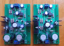
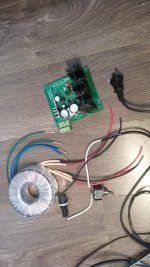
Regarding electronics, the crossovers were often quite expensive and fiddly to construct.
I more and more started overlooking designs with complex crossovers since I hadn't held a soldering iron for 20 years.

The number of speaker designs I found was still large. Although many of them were tested and built to a lesser extent.

If you know me (which you probably don't), then you know I want something that stands out a little bit.

Eventually I started going through different horn designs. Full range drivers with fancy cabinets.
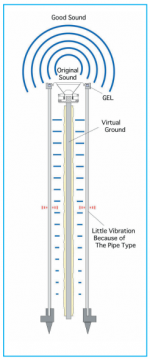
Full range drivers aim to play the entire sound spectra whereas regular drivers are targeted for a specific part of the sound spectra. For example tweeters are meant to play the higher frequencies, a bass driver aims to to play the very lowest. One of the main advantages of single driver horn designs (or transmission line speakers) is that such designs have no crossovers whatsoever. They often feature a single driver designed to play the entire spectrum and the cabinet is designed to use the full potential of the driver.

Many of the horn speakers would require a master carpenter. Despite this I kept looking at this type of design. Eventually I found a design that initially looked overly complex. It was called Frugel-Horn. The first images I had seen were of older versions of this design. The latest one was found on a slightly disorganized web page: Frugel-Horn Mk3 (www.p10hifi.net/FH/downloads/frugel-hornMk3-1v0-250212.pdf url is now 404, missing)

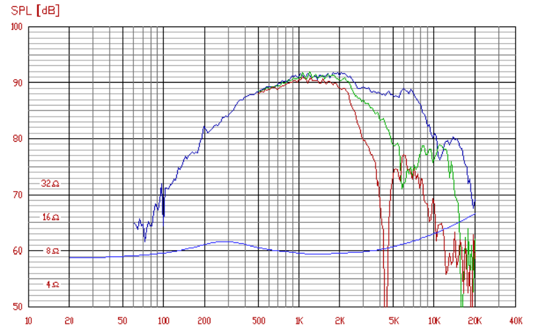
The design was fully open source and one of its goals was to keep it simple and cost effective. It was designed around a 4 inch full range driver. The design seemed old and abandoned at first, but once I started checking around I changed my opinion. The design was 5-10 years old but it was still being built! The plans even had different sound proofing based on which of the recommended drivers you would choose. They looked more and more interesting. Calculations on how low they would go and what the different drivers would be good at were available.

The really interesting thing was the plethora of opinions about this speaker. Since the plans were readily available, many had built their own. Most of the opinions were quite well formed. They inspired confidence in the design. The original design document featured plans for both 15 and 18mm walls, with a few different views on baffle thickness.

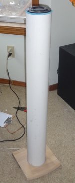
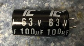
My mind was made up! I wanted a pair of these; These really beautiful speakers that wouldn't look out of place in a fancy design studio. I started looking around for the drivers and they weren't that expensive. A pair of drivers were around 140 EUR. in addition I would need terminals, MDF board, sound insulation material, anti-vibration pads, screws, glue, wires, spackle and paint. One of the advantages of this design is that it had been designed to be cut out of a single sheet of MDF. So if you ordered a single sheet of 1220×2440mm MDF that would be enough for a pair.

I placed an order for a pair of drivers and started rifling through the vast amount of forum posts on these speakers. I was looking both for tips on construction as well as practical tips and coloring ideas. I had this idea to paint them with 2 component paint like on cars. I was thinking of either Satin black, Rosso Corsa (Ferrari red) or even white. You see, I wanted something with presence. Most of the people I found had technical questions, some had audio quality discussions. Some discussions focused on the need of thicker baffles (if you went with a thinner material like 15mm).

I had been talking to my dad during this investigation. He is skilled at carpentering and had promised to help me build them. He had advised me away from designs that would be difficult to construct with any finish. He liked the idea of the frugal horn speakers so I ordered a sheet of 19mm MDF 1220×2440mm delivered to his workshop where we would be constructing them. The delivery was almost as expensive as the sheet itself but since I was unable to pick it up myself it turned out to be a decent compromise.

2015-03-07.
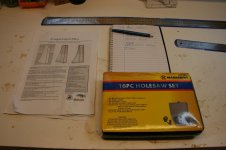
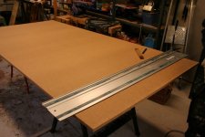
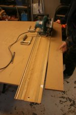
We started constructing the speakers on a somewhat cold Saturday in early March. The plan was to work as much as we could during a first weekend and then plan for further work if needed. I could do the sanding, painting and finishing back in town. I had ordered a few extra items before we started: Hole saw, speaker terminals and two metallic rulers.

717551d1543044217-frugal-horn-mk3-build-img_1676-jpg


There were several suggested ways of cutting the sheet. We chose the following one.

717552d1543044217-frugal-horn-mk3-build-img_1681-jpg


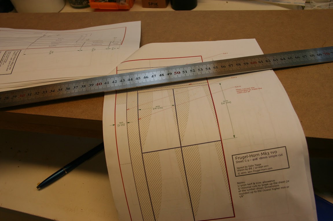
If you are to have any chance of nice cuts you will need a plunge saw. The plunge saw will ride along the ruler or guide and will give really nice cuts. We worked according to "Measure twice, cut once."; A mantra taught to me by Edd China of Discovery's Wheeler Dealers. An erroneous cut could put us out of business since we only had the one sheet of MDF. In fact much of the first day of construction was spent measuring and thinking. The plan is quite simple. Most parts will be 140mm (top, front, bottom and rear). The front of the speaker will lean back about 5degrees. This will affect many of the cuts. The really tricky part will be to create the sides. There is a long curved cut on the edge facing away from the front. This cut cannot be made with a plunge saw. Just drawing this cut will be a bit tricky. Also note that you will need to adapt the length of the parts if you use a non-standard material thickness. This is to keep inside of the horn within tolerance.

717553d1543044217-frugal-horn-mk3-build-img_1678-jpg


The very first cut:

https://www.diyaudio.com/forums/att...1543044217-frugal-horn-mk3-build-img_1679-jpg

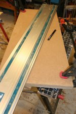
We continued cutting out the side panels from the MDF sheet and eventually ended up with two sides which we clamped together. The idea was to cut them as a pair, thus having two equal sides.

This image shows how the rearwards facing edge will be cut.

717555d1543044217-frugal-horn-mk3-build-img_1683-jpg


Having done that cut we needed something to draw the curved edge. What we did was we used the long ruler. We held it in place at the edges and moved the mid point inwards. Thus creating a curved line to cut after. My dad had a band-saw in his workshop that would be ideal to to this cut. We followed up with some light sanding with a random orbit sander which left us with a smooth edge.

717556d1543044217-frugal-horn-mk3-build-img_1684-jpg


717557d1543044217-frugal-horn-mk3-build-img_1685-jpg


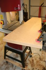
The second speaker had its side panels cut in the same way. On this speaker we drew the curved line before cutting off the superfluous material.

717558d1543044217-frugal-horn-mk3-build-img_1686-jpg


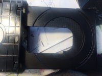
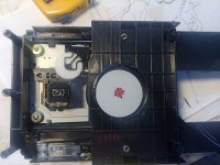
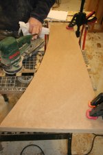
Having both of the sides panels for both of the speakers cut, we started working on the baffles. The MDF was really tough to make holes in using our hole saw. The hole saw we had did not have the exact size needed so we had to sand out the edge of the hole to tolerance. Eventually the driver fit. Having all parts for one speaker ready, we started preparing for gluing and screwing it together.

717559d1543044217-frugal-horn-mk3-build-img_1687-jpg


717560d1543044217-frugal-horn-mk3-build-img_1688-jpg

Attachments

  • IMG_1676.JPG
    IMG_1676.JPG
    127.8 KB · Views: 2,761
  • IMG_1681.JPG
    IMG_1681.JPG
    119.4 KB · Views: 2,718
  • IMG_1678.JPG
    IMG_1678.JPG
    132.8 KB · Views: 2,633
  • IMG_1679.JPG
    IMG_1679.JPG
    76.5 KB · Views: 324
  • IMG_1683.JPG
    IMG_1683.JPG
    113.2 KB · Views: 2,616
  • IMG_1684.JPG
    IMG_1684.JPG
    106.6 KB · Views: 2,503
  • IMG_1685.JPG
    IMG_1685.JPG
    95.3 KB · Views: 2,275
  • IMG_1686.JPG
    IMG_1686.JPG
    84.4 KB · Views: 2,290
  • IMG_1687.JPG
    IMG_1687.JPG
    71.5 KB · Views: 2,261
  • IMG_1688.JPG
    IMG_1688.JPG
    197.4 KB · Views: 2,260

Class D vs Power Inverter

Many power inverters use SPWM to drive a MOSFET bridge and transformer output. I have been (slowly) piecing together the knowledge to build a homemade 3-5 kW inverter. The similarities to a class D amp are many, so I wanted ask you amp guys a couple of questions.

The SPWM and feedback control are easy. I have that pretty much perfected for my purposes. An Arduino Nano has more than enough power to manage all that and then some. So my remaining focus is on the power output stage. It will handle better than 200 amps in the continuous maximum, and much more for very small transients.

I have so far built an isolated power supply for the high side FET drive and the entire H-bridge. I have attached a diagram of 1/4 of the bridge. The rest are the same basic totem pole configuration, except the low side doesn't have an isolated power supply. The switch in the diagram represents all the upstream controls. The 1 ohm resistor represents a generic load. There are actually 4 FETs in each 1/4 bridge, each with their own gate resistor and diode. A single RC snubber serves each individual quarter.

Please critique.

Attachments

  • Screenshot_20210312-113341.png
    Screenshot_20210312-113341.png
    139.9 KB · Views: 156

Digital output on Sony CDP-520ES possible?

I picked up a 1985 Sony CDP-520ES with the BU-1 laser reader in good shape. It has a CX20152 DAC and a CX23034 digital filter. Unfortunatly it has no digital output. I'm looking to pic up an external DAC in the near future to use with my other CD players and would like to make this my main deck. Is it possible to add a digital output to this player?
I checked the Alldatasheets specs for both chips and the only DOUT that I come up with is on the filter. Shouldn't I be looking for DOUT on the existing DAC? As you can see I'm not an EE or an audio tech but I am pretty handy.
Thanks

BillWojo

5AR4 "Graetz"/Dynaco Diode Mod for TubeLab boards

My "shop" Simple SE amp (with the outboard sockets for 6AV5 incandescence experiments) wants KT-88s so to play that Rock & Roll Music. I sense some jealousy of the ratty old QUAD 303.

For this mini-project, I would like to get the B+ up around 470-475vdc using current iron:
  • PST is prewar Thordarson 390-0-390v, 200mA.
  • Choke is Thordarson "swinging" choke, measures 8.5H at 100 ohms DCR

PSUD-II says that the options for a rectifier are
(1) Solid State. Nah, yeah, nah...
(2) GZ-37. HA! you make me laugh, PSUD-II....
(3) 2 x 5AR4 (GZ34). Sorry, bubba, not enuf fils current....
(4) "Graetz" 5AR4, which I believe means HYBRID rectification with 4007s on the HV terminals. IF SO, that would work great..

I assume that the 5AR4GRAETZ is like the famous DYNACO "yellow sheet" mod shown below, IIRC necessitated by the dodginess of current-production 5AR4s (have flashed TWO of them myself, one audio, one guitar, and swore them off about 5 years ago).

Is this indeed what 5AR4GRAETZ means in the PSUD-II rectifier list? Can't tell from the limited specs: PIV 1500V, IFSM 99A, IFRM 1.5A. Hopefully it doesn't mean a FULL BRIDGE S/S rectifier in front of the tube...

If so, has anybody used this mod with 5AR4s on TubeLab boards?

I assume it could be done by simply putting UF-4007s in the terminal blocks and soldering the HV leads to the diodes (with nice red shrink wrap, of course). Is that right?


In other news, I played around with a "lower impact" P/S topology using TWO surprisingly tiny chokes I have lying around (Hammond 193 H, 5H, 200mA, 65 ohms DCR). See schematic below. This gives about 470 vdc B+, which is in the ballpark.

The idea would be to use a terminal strip between the chokes, and bring the 47uF cap back to the Star Ground.
Generally, I really like 3 stage filters with low-medium-high capacitance; in this case, the PSU-II shows virtually NO ripple (eyeballing about 0.0something volts RMS; my eyeball has a square root function, but with loose precision).

If a second choke isn't available or won't fit, an RC filter works pretty well, too. I may change out the chokes simply to get the 200mA current rating.

If you're using a choke on your board ANYWAY, it's a simple mod to add a third stage to your power supply filter, and then "tone-down" each stage...

Attachments

  • DYNACO Hybrid Rectifier Mod.jpg
    DYNACO Hybrid Rectifier Mod.jpg
    39.7 KB · Views: 332
  • Shop SSE Power Supply Mod.JPG
    Shop SSE Power Supply Mod.JPG
    47.3 KB · Views: 376

High-end full active DSP 2.1

Hi everyone,
Newbie here looking for some realistic & pragmatic advice on what to consider building for a long term project.

I currently have a full active Linn Akubarik "akitiv" system.

Linn — Akubarik Speakers

And a second Linn Majik 5.1 surround system.

I've been into hifi for ~20 years and the time has come for me to begin building my own gear. I have no wood working experience and very limited soldering experience however I'm keen and not phased by learning the skills needed to build myself (I think it will be fun!).

my long term aim is to build a high end active DSP 2.1 system to replace the Akubariks which significantly outperforms them.

I'm after neutral & transparent sounding system which will go in a dedicated listening room 5.38m (17'8") by 3.33m (10'11") & height 2.4m (7'10"), the room will have treatment complimented by DSP and 2-4 subs, all centered on a single listening position.

I'm considering buying a pre-amp with built in DSP e.g. Lyngdorf room perfect RoomPerfect | Lyngdorf Audio or possibly a DIRAC solution but would consider DSP modules in active speakers, whichever gives the best sonic performance.

I'm quite realistic that this will be a long term project & the learning curve is going to be steep.

I've looked into starting with a simple bookshelf kit to learn the ropes however I think the build looks quite trivial so think I should be more ambitious.

Budget is expected to be eye watering, anywhere up to £20k ($30k) or over, but will be spent in stages over 24-36 months.

Intention is to run the main speakers down to ~100Hz with the subs handling omni directional frequencies.

Ideally I'd like to be able to start with passive mains, running them via existing retail amps, and then make them active over time as I build the power amps. Introducing more & more subs as a second stage before the mains go active.

A lot of background I know, keen to get some realism so please be blunt with your feedback and suggestions.

lots of questions given the above but the 2 key ones right now are:-
1. What is the best speaker type choice for low bass extension speakers coupled with subs? - I'd consider any type including horn, open baffle, trad cabinet etc.
2. Is "jumping in at the deep end" and building a costly pair of main speakers a sensible & pragmatic approach for a newbie? - I'm not so keen on building something I'd never use just to learn the ropes.

I'd prefer an established & proven design and have been trawling the forum, usual designers & websites but don't seem to be able to find lots of choice for "high-end" narrow band mains.

I think part of the issue is that I don't yet understand/appreciate which mid and tweeter drivers are exceptional, and therefore which designs would be world class - Suggestions on designs greatly welcomed.

I'm still in research & fact finding mode at the moment, trying to make my mind up on the right approach.

Thanks in advance

EL84 Change to 6P14P-EV

I am collecting parts for an BH EL84 PP build and would like to use 6P14P-EB in place of the EL84 for the output tubes. I know they are not a strait swap

On RU Tubes.com
6P14P-EV = EL84 = 7189 = 6BQ5 tube. Output pentode ― Hi-End vacuum tubes, sockets, capacitors, nixie. Retail and wholesale to worldwide.

it states that

'The 6P14P-EV (6П14П-ЕВ) output pentode is designed for amplification of low-frequency power.

The 6P14P-EV output pentodes are miniature devices enclosed in glass bulb and are provided with a nine-pin base and an indirectly heated oxide-coated cathode.

The 6P14P-EV electorn tube output pentodes are resistant to ambient temperature from -60 to +70°C and relative humidity of 95 to 98% at +40°C, as well as to mechanical loads: vibration loads up to 2.5g and multiple impact loads up to 35g.

These are premium quality Russian 6P14P-EV tubes. -EV (ЕВ) suffix suggests they are rated twice as long service live (7,000 hours). Tube have gold grid.

All tubes new, military equipment and have "OTK" mark. Near equivalent: 7189, 6BQ5 and EL84M. The tube is manufactured by the Reflector plant, Saratov, Russia.


General characteristics:
Name: 6P14P-EV (aka 6P14P-EB)
Type: Output pentode
Application: LF power amplification
Cathode type: oxide, indirect heating
Envelope: glass, miniature
Mass, g: 20
Filament voltage, V: 6.3
Filament current, A: 0.7-0.82
Anode voltage, V: 256
Anode current, A: 0.04-0.056
Anode power, W: 14
Grid2 voltage, V: 256
Steepness, mA/V: 9.5-14.5
Reverse grid current, uA: 0,3
Microphnic noise, mV: 250
Gain: ~20
Socket type: rsh8

Can any of the experts explain how to wire them and anything else that I need to do including resistor value for fixed bias.

I know that the 6N2P's filament will take only 6.3V pins 4 and 5.

Thanks

Lee

Luxman 550 rebuild project - calculating the bias current

I'm rebuilding the main Amp. of a Luxman-550 with new components, and want to make sure that I get the bias current right.
I have replaced the STV-2H with two 1N4001 diodes in series, but I don't know the specs for the thermistor TH801 that is put in parallel over the R802, see the uploaded schematics.

So to make sure I get things right, I want to recalculate the resistors making the bias current.

My problem is that I cannot figure out what the voltage drop is over these resistors (as indicated on the uploaded schematic). Can anyone help me?

Attachments

  • L550_Schematic.png
    L550_Schematic.png
    237.5 KB · Views: 173
Projects by fanatics, for fanatics
Get answers and advice for everyone wanting to learn the art of audio.
Join the Community
507,799
Members
7,888,913
Messages

Filter

Forum Statistics

Threads
406,262
Messages
7,888,913
Members
507,799
Latest member
Frank-el