I made a hybrid phono preamp using LSK389 Jfet with ECC88 in cascode configuration (similar to Allen Wright), with a regulated HV using Pete Millet maida style regulator and regulated heaters using LM317.
The PCB has a ground plane and for the build I`m using two cases. One for transformer, rectifiers, capacitors and heaters regulation. The other one contains the phono stage and regulated HV.
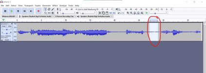
When I start the phono stage, there is no hum or noise. After around 30min to 1 hour of use I`m getting a noise on the output of phono stage (hear on attached .mp4 file).
Is this a bad regulator noise? Oscillation?
Any ideas?
Regards
View attachment phono 1.mp4
The PCB has a ground plane and for the build I`m using two cases. One for transformer, rectifiers, capacitors and heaters regulation. The other one contains the phono stage and regulated HV.
When I start the phono stage, there is no hum or noise. After around 30min to 1 hour of use I`m getting a noise on the output of phono stage (hear on attached .mp4 file).
Is this a bad regulator noise? Oscillation?
Any ideas?
Regards
View attachment phono 1.mp4
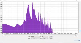
It sounds like some low frequency instability. A very basic plot of the spectrum of the noise in one of the quiet parts shows a lot peaks and general hash but nothing seemingly centred around mains frequencies.
Edit... there is a 100Hz peak. 50Hz mains where you are?
Edit... there is a 100Hz peak. 50Hz mains where you are?
Attachments
Do you think you have enough voltage across the regulator. Could you post a circuit. Both channels have the problem so something common to both. Looks like a bit of rectifier voltage coming and going as the mains goes up or down a bit. Could also be instability in the regulator at HF which we don't see.
Last edited:
The fact it takes 1/2 an hour to appear means its probably being triggered by thermal changes. Definitely mains hum, and as its 100Hz not 50Hz that means rectified mains is involved.
I'd suspect either the temperature change is increasing the resistances in the transformer, dropping the voltage before the rectifier/regulator leading to the regulator drop-out voltage being hit, or that there's simply a dodgy connection somewhere probably in the ground.
I'd suspect either the temperature change is increasing the resistances in the transformer, dropping the voltage before the rectifier/regulator leading to the regulator drop-out voltage being hit, or that there's simply a dodgy connection somewhere probably in the ground.
let it warm up on your bench, and then check voltages. You can normally diagnose this sort of stuff with a multimeter. not sure what sort of drop you need over the maida style reg.... someone here will know exactly tomchr may be worth contacting.
Could be voltage drop with heat, could be a cap or a resistor misbehaving when hot... both will be measurable (carefully) with a DMM.
Could be voltage drop with heat, could be a cap or a resistor misbehaving when hot... both will be measurable (carefully) with a DMM.
Thank you all for replying.
I did some measurements as suggested and found following:
At start-up:
High Voltage / AC=214V / DC=269V / REG=248V (as seen on maida app note, there is a 10V drop needed for regulator to work)
Low Voltage (heaters) / AC=9V / DC=9.6V / REG=7.08V (LM317 needs min 3V drop voltage as per datasheet)
After 30min:
High Voltage / AC=210V / DC=261V / REG=248V
Low Voltage (heaters) / AC=8.75V / DC=9.3V / REG=6.97V
Transformer output rating: 210V @ 90mA and 9V @ 1.2A
I`m using two PCC88 running @ 7mA or so (28mA in total) plus two mosfet followers @ around 5mA or so (10mA in total) on high voltage. 38mA total per phono preamp.
Heaters current draw is around 700mA per two tubes.
I will try to either replace LM317 with LT1084 or other regulator with lower drop voltage. Change the transformer for higher power rating.
Just sounds like a piano to me ?
Seriously, sounds like mains hum or rectified mains hum.
As it comes in and out could be a regulation problem as transformer voltage goes up and down. Regulator just on the edge of dropping out.
Seriously, sounds like mains hum or rectified mains hum.
As it comes in and out could be a regulation problem as transformer voltage goes up and down. Regulator just on the edge of dropping out.
HaHa. LT1084 sounds good to me. In the mean time adjust you heater reg for 6.3V and repeat test.
Last edited:
1084 needs 100uF on the output for stability if memory serves me correct. Read the datasheet or that thing may oscillate.
LT1084 is pricey, LD1085 will do just fine
LT1084 is pricey, LD1085 will do just fine
The Reg doesnt have much headroom... could be that (can you trim it down 5v or so on the output to give more headroom.
Other than that... scope may be needed.
Other than that... scope may be needed.
... if possible and safe (do you have a trimpott in the maida?) you could adjust whilst playing music, see if it is reg dropout.
Reading around the maida threads, 15v min is often recommended.
Reading around the maida threads, 15v min is often recommended.
I found a spare transformer and did some tests. The new transformer rating are: 0-210V @ 100mA and 9V @ 3A
After replacing it I measured following voltages after 30min:
High Voltage / AC=217V / DC=277 V / REG=248V (voltage drop around 29V)
Low Voltage (heaters) / AC=9.4V / DC=10.43V / REG=6.97V (voltage drop around 3.5 V)
Hum and instability gone. Thank you all for help.
After replacing it I measured following voltages after 30min:
High Voltage / AC=217V / DC=277 V / REG=248V (voltage drop around 29V)
Low Voltage (heaters) / AC=9.4V / DC=10.43V / REG=6.97V (voltage drop around 3.5 V)
Hum and instability gone. Thank you all for help.
Hi everyone,
I`m coming back with another issue on my phono stage. When I power off the unit I`m getting a big spike (40V DC) at the output. Initially I put two 7V zener diodes back to back between output and ground to limit the voltage and not damage the line preamp unit. Finally I`ve added a bipolar input capacitor before Jfet and the spike is gone when I switch off the phono stage.
Can some tell me where is the spike coming from? My guess is the hybrid cascode stage, but can`t understand how is created. Is there another way around, without the input capacitor?
See attached schematic.
Last edited:
The current source turns on before the tube.
The output capacitor may also be too large for the load. If load is >100k, reduce the capacitor accordingly.
Output muting (short to ground) would be best in any event.
The output capacitor may also be too large for the load. If load is >100k, reduce the capacitor accordingly.
Output muting (short to ground) would be best in any event.
Last edited:
I`m using a mute circuit with NE555 and relay (short to ground ) for power on with around 7 sec delay and works perfect, but it does not switch off fast enough for power off.
Lengthen the delay to more like 20 or 30 seconds, and use a low leakage timing capacitor.
The tube doesn't fully warm up in seven seconds, as you have seen.
Also make sure that a brief AC line power interruption will cause the timer to reset immediately.
There may be a turn-off transient as well. And when the timer restarts, it must have the full delay.
The tube doesn't fully warm up in seven seconds, as you have seen.
Also make sure that a brief AC line power interruption will cause the timer to reset immediately.
There may be a turn-off transient as well. And when the timer restarts, it must have the full delay.
Last edited:
Rayma, my issue is when I power OFF the unit. When power on, I have no issues. 7 sec delay works for me.
Ok, then are you using a normally off relay? It should be.
Or is it the timer circuit that is not fast enough to switch the relay quickly?
The supply voltage to the timer circuit has to decay rapidly upon turn-off.
Depending on the circuit, a diode from the timing capacitor to the LV power supply
first filter capacitor (right after the rectifiers) should discharge the timing capacitor quickly.
In a difficult case, an extra switch contact (or a relay) controlled by the main power switch
can short the timing capacitor to ground upon turn-off. This will always be effective.
Last edited:
Coming back to my original question. How is the 40V spike created in the cascode stage (my guess) and why if use an input capacitor solves the problem and the 40V spike at the output is gone? I want to understand that.
Last edited:
- Home
- Amplifiers
- Tubes / Valves
- Need help troubleshooting the output noise