Wrong voltage - any problem?

I have been using a little integrated amp (Teac a-h500i) in my workshop for a while now, just to have some tunes while I’m working, it’s hooked up to a pair of mini speakers, Gale 3010S, it sounds fine. I bought the amp a few years ago, local sale, and I’ve never had any problems with it.

While I was moving things around today, I looked at the rear of the amp and noticed that the label on the back reads ‘230v. 50 Hz’, which of course is not what we have here in Canada. The amp doesn’t appear to have a voltage selector switch anywhere, yet it seems to be functioning just fine on our mains of 120v, 60 Hz, without a step up transformer.

Two questions, is this safe to use as is? And am I doing any damage to the amp like this?

Tom

Impedance Curve and Dampening question

I am making Ekta Grandes with the following dampening in place from Troels Gravesen's design:

Damping of cabinet: Use 8 mm felt material and 30 mm polyester foam (Acoustilux). Add felt to all internal panels incl. mid cab except front panel and bracings. Add four layers of 30 mm Acoustilux to the bottom of cabinet and two layers to top.
Place two layers of Acoustilux behind 18W drivers and behind 12M middriver.​

With this dampening, I have the attached impedance curve. So I still have some resonances at 100 and 200khz and a bit of a ripple at 400khz. I am hoping for suggestions on where to add dampening to lower the resonances even more. I can't add anything at the bottom anymore because of the crossovers. Maybe a clue is that with the port stuffed, those resonance bumps are significantly decreased.
Thanks!

Attachments

  • Ektaleft4layers.jpg
    Ektaleft4layers.jpg
    141.4 KB · Views: 225

Anti-pop sound when tube amp turned off!

Hi all
Maybe it's about 2 years left since my 6c33 SET diy complited🙂
It's sounds so good with zero negative feedback and 12bh7 as driver and 12ax7 as pre/first stage
No noise and exactly no 60Hz hum !
Sth like a pop-sound that can be heard from speaker, is annoying me when i turn the amp off
I don't know how to solve it
I've checked whole net but topics wasn't related or useful with tube amps
Can anyone please help me in this way to solve it?
Thank u

FS Quantity of five JLester TPA3255 and power supplies MAKE ME AN OFFER!

Up for sale, a total of five pairs of unfinished TPA3255 amp boards and power supplies. All brand new. MAKE ME AN OFFER!

Each pair includes
One TICORE260BTL TPA3255 STEREO PFFB 48V (PARTIAL KIT) AMPLIFIER MODULE with the four premium coilcraft VER2923-103KL inductors installed.
One AliExpress 800w 48v low noise power supply (KAYPW Switching Power Supply Light Transformer, as used by XRK on his builds)

attachment.php


attachment.php


To complete each amp board all you needs is:
One ATS-TI1OP-519-C1-R3 heatsink (available on mouser, costs just over £5)
2 pcs OPA1656 or LME49860 on SOIC-8 to DIP-8 adapter ENIG PCB - readily available on the internet
4pc tank caps: 1800uF 63V low impedance (e.g. panasonic EEU-FC1J182, about £2 each)

Plus other ancillaries and chassis etc... which are not included.

You will need to make the following easy amend to the boards as TICore260BTL Version "V1A" has a small fault that when right channel exceeds certain power output, the module goes into protection mode. This is overcome by lifting C17, then connect the ground of C17 to ground plane on C16. (Picture attached)

Good performance from these. Any questions please ask.

Gavin
Oxford, UK

Attachments

  • TPA3255 board.jpg
    TPA3255 board.jpg
    163.9 KB · Views: 629
  • 800w power supply.jpg
    800w power supply.jpg
    98.1 KB · Views: 749
  • BTSB-Bal-Input-Noise-Floor.jpg
    BTSB-Bal-Input-Noise-Floor.jpg
    162.3 KB · Views: 376
  • fix.jpeg
    fix.jpeg
    764.1 KB · Views: 418

JBL2226 VS black widow1504 folded horn

hi
I have been looking for a folded horn for a long time, I almost built and then I found the peavey fh-1.
I understood from reading in the forum that the jbl2226 speaker is very high quality for folded horn, so i buy one, in addition to other forums they preferred it over the peavey black widow 1504.

What do you think about the results?
the black widow 1504 is little more punchy


measure at 0.2 meter normal level

Attachments

  • FH-1.JPG
    FH-1.JPG
    136 KB · Views: 313
  • IMG_20210408_204928.jpg
    IMG_20210408_204928.jpg
    490.3 KB · Views: 428

Cables for Mark Levinson No. 30.5 and PLS-330

I have resurrected a Mark Levinson No. 30.5 digital processor / preamp from storage, along with its companion PLS-330 power supply. However, the cables that run between the 30.5 and the 330 are nowhere to be found. I would like to build some replacements, or have them built. There are three cables: two (i.e., left and right channel) "analog dc" cables; and one "digital dc" cable. I have included a photos of two of the ports on the back of the PLS-30 for reference. From the ports, and from photos I have seen of the cables online, it appears the cables use Lemo push pull connectors, 5-pin for the analog dc cables, and 2-pin for the digital dc cable. These connectors are available. I do not know the actual cable that was used. I have not been able to find any pinout info. I also have not been able to find schematics for the units.

Since these are basically just patch cables, it seems straight forward enough (isn't that where the problems often begin, "Well, it seemed simple enough...."). Just make sure the connectors on each end of the cable are wired the same. As for the actual cable, a starting question seems to be whether the cable should be shielded. I note that the Mark Levinson AC cord for the PLS-330 is shielded. That makes me think these should be shielded as well. Another question is whether the shield is connected to a pin on either of the cables. Thoughts? What else do I need to consider?

Thanks for your help.

Attachments

  • ML Cable Ports.jpg
    ML Cable Ports.jpg
    488.4 KB · Views: 188

Dynaudio Contour Improvement

Hello
I have 2 Dynaudio Contour 2 loudspeakers and I simulated their crossover with VituixCad software (very well done, congratulations!). I don't understand why if I connect the 3 speakers with the same phase (as all theories say for a 1st order filter) a deep depression at 1400hz is highlighted !!! If I invert the polarity of the mid-range the response improves! See attached diagram.
Thank you

Attachments

  • Cattura.PNG
    Cattura.PNG
    497.1 KB · Views: 201

FS: Antek 300VA 20V and 24V Transformers

Good afternoon,

The power supply for my recent build went through a few iterations, and left me with some spare transformers. I have two Antek 300VA transformers, with 20V (AS 3220) and 24V (AS 3224) primaries. Both have under an hour of use on them, and have ring terminals soldered on the primaries, and 0.250" spade connectors crimped on the secondaries. I make no guarantees to the quality of these connections, but the leads weren't shortened so there should be plenty of length left if you want to redo them.

AS 3220 - $40 shipped.

AS 3224 - $40 shipped. The purple shield lead has been shortened a few inches, and the mounting bolt was cut so it didn't contact the top of the chassis.

Ships only to US - apologies to my international brethren.

Thanks for reading. PM me for more details or questions.

Attachments

  • 20210420_144651.jpg
    20210420_144651.jpg
    732.9 KB · Views: 276
  • 20210420_144740.jpg
    20210420_144740.jpg
    531.7 KB · Views: 243
  • 20210420_144825.jpg
    20210420_144825.jpg
    606.2 KB · Views: 238
  • 20210420_145312.jpg
    20210420_145312.jpg
    590.3 KB · Views: 229

Twisted Sounds 8.5k

I've got the power supply up and running and I have the correct rail voltages but I cant get it to oscillate even when I drive a sine wave into it. I've replaced both 21844s chips twice and checked all of the a1715 and c2814 transistors.

Attachments

  • 20200710_104305.jpg
    20200710_104305.jpg
    1.1 MB · Views: 259
  • 20200710_104352.jpg
    20200710_104352.jpg
    936 KB · Views: 261
  • 20200710_104427.jpg
    20200710_104427.jpg
    851.1 KB · Views: 229
  • 20200710_104448.jpg
    20200710_104448.jpg
    1,019.4 KB · Views: 223

NEW PCB: Active loaded triode High Z 9AJ voltage amp.

Hey everyone.

I've created a new PCB for an actively loaded triode voltage amp for the front end of my MA-1 power amp design for those who wanted to make it an integrated amp instead of using a separate preamp.

It has been built and tested, and works as expected.

It uses the larger 9 pin socket 21 odd mm instead of 18mm

I have a few left, and I will offer blanks, kits, and completes, but I'm also offering up the Gerber as an open source project.

Koda

EDIT: Schematic error, see post #5

Attachments

FE206ES-R, first impressions

Hi,

today I got a chance to test my Fostex FE206ES-R. I didn't had the time to build the recommended horn enlosure so I un-screwed my Hemp FR8.0 and used my 2 cu.ft reflex cab. I used a 8.2 ohm series resistor to get him reflex-friendly 😉

First impression: good bass (45Hz), very detailed midrange, clear high range. A quick plot shows 92dB up to 2000Hz with a 4dB rise to the top end (even with the 8.2 ohms resistor!).

A very nice driver to play with ......

Regards
Thorsten

Attachments

  • fe206es-r.jpg
    fe206es-r.jpg
    19.2 KB · Views: 3,613

Using Microsoft Excel Solver to Find a SIT Sim Model Parameters(1)

“A Concise Model for Static Induction Transistor IV Characteristics” - Michael Rothacher
In his publication, a equation is given to find model for simulation:

Id=K*(Vg+Vct+N*LN(Vd)+Vd/Mu)^X

.SUBCKT TFH51S D G S
+ PARAMS: K=0.157 MU=7.3 N=2.24 X=1.51 VCT=0.0
B1 D S I=K*PWR(URAMP((V(G,S)+VCT)+(N*LN(V(D,S))+(V(D,S)/MU))),X)
.ENDS TFH51S

Another attempt at (stealing) making a Synergy speaker.

Hey!

I am in the middle of building a synergy speaker based on ideas of xrk971 and Bushmeister. Yeah, i have basically stolen their ideas because i thought they are that awesome. Thank you guys!

I am using the same waveguide, only i decided to use pro drivers. The drivers i've chosen are Beyma 8G40 for midbass-lowmid and Faital HF146 for upper frequencies. I love the dynamics of pro drivers so i decided to go this route.

Now, since Beymas are capable of taking much more power than SB drivers, the size of the ports should also be larger. The question is - what would be the maximum size of the ports that is not damaging to the waveguide (causing too much diffraction)?

While the driver's is 220cm, I am currently aiming for 4 ports 50x60mm (30cm2 area) each, 2 per driver, which makes 60cm per driver. Is it too much? To little? Is it too close to the HF driver? I can't go any further from apparently because then i am touching the mid bass speaker.

I am going to cross the speaker at about 80-100Hz and will use a sub. The speakers will be used in a home theater and in a 2.1 configuration as well.

Here you can see some work in progress:

854502d1592669010-attempt-stealing-synergy-speaker-start-jpeg


854503d1592669010-attempt-stealing-synergy-speaker-start22-png


854504d1592669010-attempt-stealing-synergy-speaker-5-jpg


854505d1592669010-attempt-stealing-synergy-speaker-2-jpg


854506d1592669010-attempt-stealing-synergy-speaker-3-jpg


854507d1592669010-attempt-stealing-synergy-speaker-1-jpg


854508d1592669010-attempt-stealing-synergy-speaker-6-jpg


854509d1592669010-attempt-stealing-synergy-speaker-7-jpg


854510d1592669010-attempt-stealing-synergy-speaker-8-jpg

Attachments

  • start.jpeg
    start.jpeg
    57.4 KB · Views: 743
  • start22.png
    start22.png
    253.1 KB · Views: 734
  • 5.jpg
    5.jpg
    67.9 KB · Views: 744
  • 2.jpg
    2.jpg
    52.7 KB · Views: 745
  • 3.jpg
    3.jpg
    67.7 KB · Views: 756
  • 1.jpg
    1.jpg
    60 KB · Views: 753
  • 6.jpg
    6.jpg
    78.4 KB · Views: 755
  • 7.jpg
    7.jpg
    72.5 KB · Views: 979
  • 8.jpg
    8.jpg
    48.5 KB · Views: 990

DIY the device of US Patent 4,899,387

This expired patent is entitled "Active Low Frequency Acoustic Resonance Suppressor". It was granted on Feb. 6 1990 to Threshold Corporation; Nelson S. Pass inventor. His inventive device eliminates standing waves [SW] in rectangular music listenning rooms. Thus it enhances the accuracy, perception and enjoyment of music etc...IMHO, this device is a must tool for DIYaudiophiles. For a couple of years, I've had 2 diy stereo resonators, and have recently prototyped a third mono device [for this thread]; all in my rectangular music room.

I hope that Mr. Pass has no objections, and there is interest in diy'ing [his approach] to solve this fundamental and pervasive problem. I'll wait a week before I move forward.

Best regards.

FS: Pair of James JS-6123HS OPT's

SOLD: Pair of James JS-6123HS OPT's

You know what these are! What a shame about James but here is your chance to grab a set! Work perfect! Minor scuffing on the top but could be buffed out. I soldered male disconnects to the terminals to allow quick impedance changing.

$450 shipped to CONUS. Contact me for outside of USA price.

SOLD!

Attachments

  • IMG_5339.JPG
    IMG_5339.JPG
    296.3 KB · Views: 380
  • IMG_5338.JPG
    IMG_5338.JPG
    295.2 KB · Views: 388

Off the shelf versus PC for high-end DAC + Streamer +DSP

I'm looking at high end DAC, streamer & DSP for my system but unsure of the best approach. I'm open to self build options and/or buying off the shelf components, would welcome peoples thoughts and opinions.

Options range from a single PC device running Streamer with DSP and DAC as well, or off-the shelf DAC with PC based Streamer + PC DSP, or instead all 3 components could be off the shelf.

I don't know if there are any DIY non-pc based DAC options which are viable for high end, but I'm wondering if a DIY DAC chip per channel (L+R + each sub), might be something to consider. I'm think this from an active speaker with combined DAC architecture approach, not plate power amp but more a co-located power amp + DAC with short speaker cable run (I hate lots of cable everywhere and will avoid it if I can).

Main benefit of a PC based DSP would be number of taps available, which if I understand correctly will mean that a PC based DSP solution "should" be the highest quality DSP option available.

Challenges
1. Noise - I'm concerned about EMI/RFI generation & injection into the audio chain when using a PC. Other than building a high quality isolation case, are low noise PSUs available for PCs, what about low noise components?
2. USB - for streamer to DAC the USB interface would appear to be the best choice, but how to isolate the USB correctly and provide the right filtering?
3. Not sure what practical options exist in a PC to ensure high quality clocking
4. I'm not yet sure about reclocking e.g. Mutec, but it could be an option to try at some point, would this be workable with PC streamer/DAC?

to illustrate just how much I overthink these kind of things, I've currently retrofitted 8mm aluminium plate into my streamer along with sheets of noise absorption material to isolate from external noise, noise from the PSU and noise between the boards, it's clear to me that this provides an improvement.

Whatever solution I go for I'm highly likely to make 10mm custom cases for some (all) of these key components with separate cases for high quality PSUs - this would likely apply to rehousing off the shelf equipment if I don't go down a DIY route.

I'm sure some people will think I'm crazy 😀 given the cost & effort of doing things like this I personally think the attention to detail is worth it.

my insanity knows no bounds!

B&K 707 Tube Tester

Hi all,

I've a B&K 707 on the bench for servicing, was given to me by an old tv/radio tech.

I've already replaced caps and resistors since they were out of range, calibrated the unit sucessfully, so I think is working fine. I haven't replaced the 83 rectifier with a pair of SS 1n4007 for keeping it all original...

Now, if I test a 12AU7(ECC82) or 12AT7(ECC81) they measure fine on the meter,
If I test a 12AX7(ECC83) (tried some new JJ / EH and also some Nos Siemens) I read around 25 (chart states * good if 22 or more) still a 22 on 120 scale seems odd .

So, I want to ask you guys, is a B&K an accurate tester? It's worth keeping ?
I don't understand how can you measure a 12AU7 and a 12AT7 (different beasts)by just turn the shunt by 1 cent ? 75 vs 74
Also, how can you measure a 12AX7 on it?

Can someone otherwise suggest me a DIY project ?

Thanks

Attachments

  • chart.JPG
    chart.JPG
    19 KB · Views: 178

Bookshelfs using Proton 285 car speakers

Do magnets age? Proton 285 for home use.

Hi.

Friend gave me these old Proton 285 2-way car speaker component units. (Pic1) I think car audio days for these have passed, so idea is just to make them a sealed box for home use, that idea became because I measured one of the woofers (w3) and the parameters seemed such that they could work in 8+ litre sealed box. I have 4 woofers but parts for 2 whole units. Problem is that after measuring all the woofers there seems to be quite much difference in driver parameters.

So, the question is, are these differences caused by. 1.My measurements. 2. Factory tolerances (these are made probably mid -90s) 3. Due the ageing.

Here are the measurements:
T/S Parameters taken using DATS v2 (I used added mass and test box method and got similar results.) Impedance curves in a Pic2

w1
Fs 61.2Hz Qts 0.56 Qes 0.62 Qms 5.54
w2
Fs 58.5Hz Qts 0.84 Qes 1.0 Qms 5.1
w3
Fs 42.4Hz Qts 0.43 Qes 0.53 Qms 2.1
w4
Fs 46.4Hz Qts 0.77 Qes 1.13 Qms 2.4

All were similar with Re around 3.4ohms, Le 0.33-0.46 and Mms 7.5-8.3g

There is slight differences between looks with these two pairs and also with parameters, w1 and w2 might be older and have higher fs. Because impedance curves seem more alike with w1 and w2, I thought to use them but then there is that Qes and also Bl difference (w1 Bl4 w2 3.4) and that "sensitivity" difference shows also in a modelling.

Pic3 is w1 and w2 measured in a 8.1l test box, 50cm away with same 1.23V drive level in a room but IR windowed.


That sensitivity difference of about 3dB and Qes difference worries me, can this be because the age. Has two of these woofers lost magnetism or are there something else going on and can anything be done about that?

Thanks for any ideas, I have been lurking some time on this forum and gotten much great information but now I'm posting for the first time.

Attachments

  • Pic1.jpg
    Pic1.jpg
    217.6 KB · Views: 90
  • Pic2.png
    Pic2.png
    44.6 KB · Views: 102
  • Pic3.jpg
    Pic3.jpg
    233.1 KB · Views: 88

FS: B1 Pass buffer

Hi There,

I am selling this B1 PassDIY buffer to cover the cost of parts and materials.
Built it for an audiophile friend and he doesn't want it anymore.

I used the board and Jfets from PassDIY site. It has 2 inputs and 2 outputs.
The volume pot is Noble.
The small power supply is regulated ( 18V output ) using LD1085V.
The antivandal switch has a blue LED light ring.
The RCAs are Neutrik.

I am asking $300 plus shipping.

Attachments

  • IMG_6795.jpg
    IMG_6795.jpg
    365 KB · Views: 707
  • IMG_6796.jpg
    IMG_6796.jpg
    337.8 KB · Views: 701
  • IMG_6797.jpg
    IMG_6797.jpg
    426.5 KB · Views: 705

Some open baffle subwoofer design help needed

I’m looking to build a simple three-way open baffle using this 15 inch driver and matching it to a GRS 10 inch planar mid range. I’d like to have the mid range hi pass filter start around four or 500hz. The front baffle of the subwoofer is drawn at 21 inches in my CAD but can be adjusted somewhat. I’d like to have a U Frame rather than an H frame for aesthetic reasons but I’m having trouble calculating the size. Someone told me I should cross the subwoofer at 100 Hz and the mid range of 500 Hz due to open baffle effects. So does the U frame get calculated on 100 Hz? The MJK paper on U frame subwoofers says they should be crossed at 200 Hz, so should I go with that?
Also, the midrange/tweeter baffle shape has to stay somewhat similar to my CAD due to it being a WAF-approved design, but should that upper section be a U frame as well? Can it be (for matching aesthetics)?


An example of a similar design to my own:

Raal-848x1536.jpg


An externally hosted image should be here but it was not working when we last tested it.

15" High Excursion Paper Cone Subwoofer Driver 4 Ohm

Thiele-Small Parameters
Resonant Frequency (Fs) 34.5Hz
DC Resistance (Re) 3.79Ω
Voice Coil Inductance (Le) 1.96mH
Mechanical Q (Qms) 8.03
Electromagnetic Q (Qes) 0.86
Total Q (Qts) 0.78
Compliance Equivalent Volume (Vas) 3.46ft³
Mechanical Compliance of Suspension (Cms) 0.121mm/N
BL Product (BL) 12.96T·m
Maximum Linear Excursion (Xmax) 7.5mm
Surface Area of Cone (Sd) 755cm²

Taramps smart3 issue

I received the amp from a friend after it quit working his explanation was he was driving around and after a lil while he turned the head unit all the way down went into store came out started car and he heard a pop amp went into protect.

So after looking at it there was only one shorted output fet
So I changed the output fets, output drivers, output driver buffers.
So on one bank it appears it's modulating and waveforms look like I would assume to see however the other bank is have an issue and the low side drive isn't present for some reason I have all the correct voltages on the driver Ic expect for the low side output and I've tried to troubleshoot to the best of my abilities but I'm not to familiar enough with brazilian style amps.
I added some pic to help you understand what it I'm seeing!

highpass filter for super tweeter question.

im planning on adding super tweeters to my sansui full range speakers. what value of capacitance is required for a 2nd order hpf @10khz if i already have the inductor which are 0.30mH? Or is it even possible? i know there are calculators online but i want to use what i already have if possible. thanks in advance
An externally hosted image should be here but it was not working when we last tested it.

Cyrus PSX diy - Advice needed

Hi,
I just bought a diy PSX, and I would like to know an opinion from you. Is it well constructed? Is it "safe" to connect it to a Cyrus Two?
Here ar some pix of the diy PSX internal:
http://img141.imageshack.us/img141/8504/dsc05788md.jpg
http://img11.imageshack.us/img11/5329/dsc05787h.jpg
http://img827.imageshack.us/img827/8...6194048641.jpg
http://img717.imageshack.us/img717/9533/dsc05784r.jpg
..and here is the Cyrus Two power supply schematic:
cyrus_2_power_supply.pdf

thanks in advance

Floating bias supply.

There is often a time when a low current low voltage floating supply is required. I have used the following method most successfully on some of my solid state microcontroller projects.
It is a little known fact the base collector junction in a standard optocoupler works like a solar cell and produces an electric current. The junction works as a current source with a silicon diode shorting it out such that the voltage across it never exceeds about 600mV, from zero to 600mV it has a current transfer ratio of about 0.01 so 10mA into the LED will produce a current of about 0.01mA out, this action is quite linear and also quite fast unlike the action of a 4N27 operating in its normal transistor mode. I have used this topology to produce a reference voltage many hundreds of volts above and below ground. Some tube circuits the have a bias battery and can be modified using this style of floating supply. Care must be taken to ensure the drive to the LED is clean, hum in equals hum out, one could even filter at the output as the z is high and caps would be small.

As the supply output is fully floating it can be connected anywhere with any polarity.

The 4N27 LED's have a forward voltage drop of about 1.2V so most of the time a few of the input LED's can be connected in series.
Ken K

Attachments

  • neg_1200mV_supply.png
    neg_1200mV_supply.png
    34.1 KB · Views: 224
  • BIAS supply.asc
    BIAS supply.asc
    1.3 KB · Views: 69

RCA LC-1A 15" Driver

EXTREMELY RARE!

RCA LC-1A driver. sounds great. domes in perfect shape, but, has a damaged spot on the cone. easily repairable. I have a video of it playing.

Serious buyers only. $1000 plus shipping

Attachments

  • 20210418_195516.jpg
    20210418_195516.jpg
    1 MB · Views: 401
  • 20210418_195454.jpg
    20210418_195454.jpg
    980.6 KB · Views: 407
  • 20210418_195536.jpg
    20210418_195536.jpg
    1,011.8 KB · Views: 385
  • 20210418_195256.jpg
    20210418_195256.jpg
    819.7 KB · Views: 398

Cable help please

Hi hope somebody can help with suggestions please. My phono stage and integrated amplifier are located some distance away from each other and for various room layout reasons I would like to retain that. The distance a cable would travel would be approx. 10M. If this is operating at line levels e.g. 200-300mV what cable type would be best to avoid noise pick up or system issues. Would standard twin individually screened audio cable be sufficient or would I need something special.
Thanks
Mark

downside wiring primary for 220 to halve secondary volts? Aleph J

I have a big toroidal audio power transformer that can be wired for 120 or 220. It's from a home theater amp so it has six secondaries with around 32-0-32 originally running class AB with a published 120 watts per channel. At the IEC the rear panel says 1200 watts maximum. I wired the primary for 220, fed it with USA line voltage (117) and paralleled three secondaries for each channel of my DIY Aleph J, and it runs fine at +/- 19.5 volts .85 amps per irfp240. Two questions: any downside to doing this? ; and, what does halving the voltage do to current capacity on the secondaries? (I believe running three secondaries in parallel triples current capacity, but what about simply halving the voltage for each secondary: is the secondary capacity a watts / VA calculation or is it just a matter of the magnet wire gauge [which obviously is unchanged]?)

Resistor end-cap corrosion? Ohms reading way high...

This little 3mm has something going on around its end cap. Nominal resistance is 10k ohm. But I get high, and inconsistent, readings on my LCR, it shows 60k one time, 200k another time.

What is this corrosion? Is this a known failure mode?

This resistor is from a RCA MPA-120, an STK amp from 1987. There are a lot of these little 3mm resistors in it. And a few of them are showing similar corrosion...or whatever that is. But the end caps on most of them appear clean.

Anybody seen this before, or have any knowledge to share?

Attachments

  • DSC06267 cr900.JPG
    DSC06267 cr900.JPG
    456.1 KB · Views: 135
  • DSC06275 cr900 .JPG
    DSC06275 cr900 .JPG
    444 KB · Views: 133

The most recent problem with my F5 build

Hi all, I am still having problems with my F5 build. I still have 26 dc volts on both channels of my power supply. I believe I have the right jfets in the right places. I am working as recommended on one amp board at a time. I still have no output. No changing of the trim pots makes a difference. I get .1 mv dc across R11. I have attached pics. Any ideas other than this project was over my skill level?

Attachments

  • 6F3D6F49-C52A-4B85-93FD-A827A889B6D5.jpg
    6F3D6F49-C52A-4B85-93FD-A827A889B6D5.jpg
    954.9 KB · Views: 340
  • 3687D9FE-E07B-4FD5-9D7D-4ED3ACE3376C.jpg
    3687D9FE-E07B-4FD5-9D7D-4ED3ACE3376C.jpg
    1,023.2 KB · Views: 316
  • 39D309F2-180F-485C-88FA-14F76B60138C.jpg
    39D309F2-180F-485C-88FA-14F76B60138C.jpg
    917.6 KB · Views: 322
  • 597B88DD-BDAB-457E-B80A-ACF7C6982E3F.jpg
    597B88DD-BDAB-457E-B80A-ACF7C6982E3F.jpg
    991.5 KB · Views: 304

Sonotube Boombox

Hey everyone,

I'm starting to formulate a plan for a luggable, battery-powered boombox for summer fun and wanted to solicit input from the folks here. My goal is for it to be reasonably portable (<20lb), not be excessively large, have at least 2 hours of battery life, and be reasonably loud outside - not concert volume, but enough to dance to.

I'm thinking it'll be a 3-way system, with a sort of "mailbox" shape built around a 12" sonotube that will act as the box for the 10" subwoofer. I think I'll probably use a 6S LiPo battery to power it, with a nominal voltage of 22.2V and 88Wh capacity. I've attached a photo of a similar build that I did in 2016, with an 8" sub in 10" Sonotube, detachable speakers, and no battery. For this build I want to get a bit more LF extension and portability.

For the sub I'm thinking the Dayton Audio LS10-44, it's a 10" low-profile subwoofer that's pretty light (11lb) for how low it can go. It also can be wired to 2 ohms so I don't need a high system voltage. Not particularly efficient at 86.5dB sensitivity, though.
My plan is to give it a 30L enclosure tuned to 40Hz, for a peak of 109dB at 50Hz, 100W input.

For the mids I'll probably do these 4" GRS woofers and for tweeters these cheap Goldwoods

Then for the amps I plan to use this 100W Dayton mono amp for the sub and the 2-channel version of it for the mids/tweeters. I like the look of these amps cuz they're cheap, small, and have DSP so I can add dynamic bass boost to give it extra LF extension at low input amplitude.

What are everyone's thoughts? Is the LS10-44 good for this job, or should I pick a more efficient sub and use DSP to even out the response? The low system voltage cuts out a lot of higher impedance subs, but if it's really worth it I could do a larger battery pack.

Attachments

  • 20160117_231315.jpg
    20160117_231315.jpg
    1,022.5 KB · Views: 194

Connect Bluetooth to Crossover

Good Day,
I’m looking at building a set of 3-way speakers, which would require a crossover network. I know how to design a crossover filter and connect it to the speakers. But I would also like to make it Bluetooth.
I have found several articles explaining how to connect Bluetooth to an internal amplifier, but nothing on how to connect it to Bluetooth. Is this something that can be done, and if so, can it be done without the amplifier? Does anyone have any drawings or diagrams that you can share?
Thanks in advance.

Comteck

Need some advice for the office setup

I don't have time currently to get into the search for an amp so I am hoping for some suggestions.

Looking for a sub 100€ class D amp, to power some older Dual 4ohm bookshelf speakers in the office. Sensitivity is on the low end, as far as I remember. The office is really small 3x3m.

Given the fact that the desktop is rather old ( have some programs installed which I need and are not available anymore), should I consider getting also a separate DAC?

Many thanks!

FOR SALE : ASC Blue Line 50 uf caps

1200 vdc. photos available on request.
I still have five ( 5 ) matched pairs available. Matching done by Parts Connexion. All new, never used.
As you all know they are no longer available.
Price when new was 50.00 each plus $ 1.00 matching fee, making a new pr go for $ 102.00/pr.

Price is $ 65.00/pr. Shipping on me.

Would prefer lower 48 only, but will ship internationally under the following guidelines.
I will not lie on the customs form.
Shipping only via a service that can be insured. Shipping and insurance on you for international buyers. Since it must be insured that rules out USPS first class mail international ( cheaper way ), leaving only the more expensive options. It will be pricey.
E-mail w/ any questions.
Thanks for looking.
PayPal only.

Cheers, Crazy Bill

Disregard lower replies. They apply only to the pair I sold here. this price will never go lower than $ 65.00/mp including shipping

BSC line-level build

Thought I'd share my build with the community - maybe this will be helpful to a few folks?

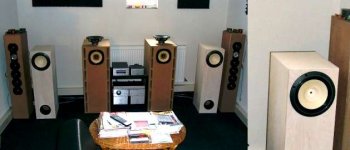
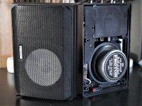
During lockdown I built a pair of Scott's Chili Changs with the Fostex FE167E drivers I've had sitting in some inappropriate cabinets for 10+ years. Lovely, lovely! I could rave on about the Chili's until the cows come home and will post a thread on the build when I get time - but, like most single full-range driver speakers they sound awful without Baffle Step Correction. As far as I understand it, full-range drivers in a tall floor-stander have a natural roll-off of the lower frequencies related to the point at which the speaker transitions from behaving as a spherical emmitter to a semi-spherical one. The roll-off is determined by the width of the baffle. The resulting sound can be described as tiring, shouty and lacking in bass.

In commercial single-driver floorstanders, the BSC is carried out by the crossover. I don't want a crossover...

I'm driving the Chili's from my Son Of Zen DIY monoblocks. I can adjust the wattage of the amps with a 240v variac and I usually run them at 5-10 watts. As they are single-ended class A and the speakers are ridiculously efficient, I don't want to stick inductors and capacitors into that part of the system reducing the efficiency so I decided to to this at the line level.

There is some really useful info on line-level BSC design here: Baffle Step Compensation
Luckily, my pre-amp output impedance is low and the input impedance of the mono-blocks is high so I don't need to use op-amp impedance buffering and can keep the design completely passive.

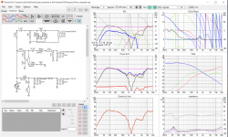
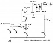
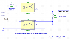
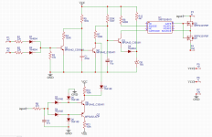
This is the final filter based upon the sound-au site, after building a prototype and playing with component values:

BSC-Circuit-sml.jpg


The filter is adjusted through a 4 position slide-switch (not shown on the diagram). From (roughly) 3dB to 6dB cut.
C1 provides the midrange roll-off... -3dB at 530Hz - but I found the top-end was very dull. So, I added C2 which alters the filter from low pass to band-cut. After playing with the values in the spice simulation and the real world, I settled upon 4.7nF... HF restored!

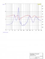
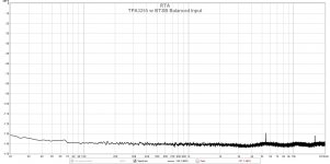
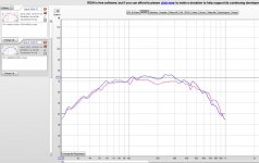
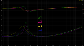
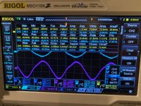
Here's the final simulated filter behaviour showing the output at the -3, -4, -5 and -6dB taps from the resistor ladder:

BSC-simulation-Final-sml.jpg


You can see that the -3dB point (7.07 volts) is pretty close to 530Hz in the lower switch positions which is the suggested -dB point for a 215mm baffle.

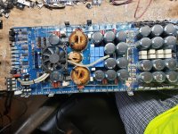
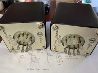
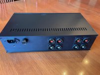
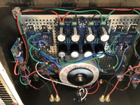
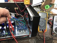
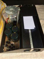
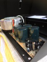
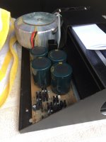
As I'm using a balanced-line connection between my Alchemist Forsetti Pre-amp and the Son of Zens, I had to double-up the filter so there are 4 discrete filter circuits - left+, left-, right+ and right-. Initially, I wired this point-to-point resulting in quite a messy prototype:

Bsc-dsc-0083-sml.jpg


I told you it was messy...
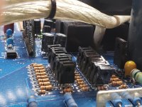
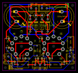
...so I laid it out on Veroboard using the DIY Layout Creator from diy-fever.com. The layout below shows one channel:

BSC-vero01.jpg

BSC-vero02.jpg


I took the opportunity to add a stereo/mono switch as the preamp doesn't have one and I often listen to mono albums. I used more 4K99 resistors as buffers at the output of the filters. Shorting the ++ and -- outputs from each channel together with a DPDT switch achieves the mono result.

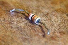
A quick note on components... I used 0.1% precision resistors I had laying around and further increased the symetricallity of the filter by matching the resistors I used with a multimeter. I also similarly matched the polystyrene precision capacitors. I used multi-strand silver wire and high silver-content solder throughout.

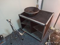
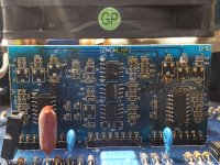
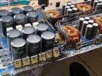
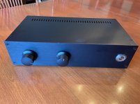
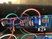
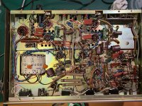
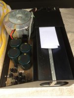
Now, the tidier version:

Bsc-dsc-vero-sml.jpg


I can thoroughly recommend line-level BSC. A much higher level of accuracy and symetricality can be achieved, and there is no effect on speaker efficiency. It's easily implemented if you have separate pre and power amps. (If you're using an integrated amp then I guess you could plumb it into one of the record loops.)

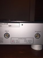
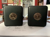
Now I need to find a use for the extra hole in the front panel...

Stay safe and keep building, folks!
  • Like
Reactions: maty tinman

ISO FC20s for 300b SET

Hello to all,

I'm just about pulling the trigger on ISO FC20s for a point to point Tubelab SE-II and am wondering if there are better irons for the same price or below available in Europe.

Monolith falls apart, as I'm not willing to pay that much.
How about the Lundahl's LL1620 or LL1623? Better bass response than the ISOs due their bigger physical design?

Many thanks and best
Ralf

Oscillating PP amp (Lafayette LA-224B)

Hi,

I've almost got no hair left after trying to figure out why my amp's right channel oscillates at 50Khz.

I've recapped it, all resistors are original but measure within 1%. Voltage levels seem fine.

When the amp oscillates, it gets pretty endemic, and is evident in the entire chain, from input to output. Even left channel gets affected a bit.

Now, for some facts:

  • Removing V4 (amplification after volume control + inverter) takes away the oscillation, but then right channel is of course dead.
  • Bypassing cathode resistor of V4a (i.e. disabling the feedback loop) also takes away the oscillation.
  • Swapping tubes around, or putting in new ones, has no effect
  • Running the amp at a lower voltage (<180V, this is a 220V amp) lets it work fine within a certain range of the volume control (not too low, not too high)
  • Input signal strength does not affect oscillation. The only thing that I can do to affect it directly is to adjust the volume knob. Low volume and high volume both increases oscillation, somewhere in the middle either lowers it a bit, or, if I run amp at a lower line voltage, removes it.
  • Oscillation doesn't start immediately, amp works fine for a few seconds before it kicks in.


I've run in so many circles, I don't know where to go. I'm also an amateur, so it's probably something very evident I'm missing. It seems to me there are no grid stoppers here - or, in the case of V4, I guess the volume control kind of acts like it. That's the closest I've come to something that makes sense based on whatever literature I can get my hands on (combined with my limited skillset).

I've attached the schematics, plus a few pics. Hope anyone can shed some light on this. It's a beautiful amp, but I spend way too much time during the day pondering about what's wrong with it, and finding no answer :bigeyes:

Attachments

  • IMG_3382.jpg
    IMG_3382.jpg
    1,014.9 KB · Views: 202
  • Lafayette_LA224B.pdf
    Lafayette_LA224B.pdf
    142.3 KB · Views: 104
  • IMG_3347.jpg
    IMG_3347.jpg
    1.1 MB · Views: 230

STK amp with .67 VAC on output

RCA MPA-120. I have two of these amps, so 3 good channels to compare voltages. The channel in question has VAC readings as shown in the pic on what appear to be the STK output legs. The readings are AC Volts, not mili-Volts. The three good channels do not look like this.


Could something other than a bad STK be causing this?

In working with these amps I have found lots of bad solder joints as well as several capacitors that are completely shot, i.e. reading 0uF.

I don't have o-scope-ability, but plugging in a speaker the voltage sounds like 60Hz or 120Hz. Not very loud but its there.

Bad STK...or possibly something else?

Attachments

  • MPA-120 main STK area - marked.jpg
    MPA-120 main STK area - marked.jpg
    260.6 KB · Views: 157

How to test an IR2110 output stage

Hi All,

I'm having a go at building a class D audio amp that uses an IR2110 MOSFET driver. It's based on the IRAUDAMP1 reference design and the full circuit can be found here: How to Build a Class-D Power Amp - Projects

So far, without the MOSFETs plugged in, everything appears to be working nicely until the output stage, where the low output side is oscillating nicely but the high output is DC. My understanding is that this is expected - both MOSFETs must be attached for IR2110 bootstrapping to work.

My question is how can output side be methodically tested?

In other words, how can I test the difference between something being actually wrong with the input side or IR2110 itself versus an output driver problem? Both scenarios can result in a short circuit for at least 50% of the duty cycle. This is what I'm getting and I've crept up the OCP on my power supply to about 80mA per rail - as far as I'd like. Is there some other sink I can use that does not risk a short? MOSFETs tested out fine, btw (well, not the first pair 😉)

176830580_10158736806617424_6736082646079542547_n.jpeg

176769302_10158736811977424_5032273880531345352_n.jpeg

Building speaker protection board with MOSFET relays

Hi,
I am starting a new guitar amp project (solid state) and will be starting a thread on it at some point soon. I want to start by building a speaker protection PCB so that I don't destroy the speaker when testing it.

I was going to etch and drill something myself but I'm placing an order with JLC PCB in about a week's time for a different project so I thought it would be a good idea to lump it in with that. I also need to use a part that is only available in SMT so will need a two layer board.

I've put together a design based around designs from Douglas Self and Rod Elliott. It incorporates Elliot's MOSFET relay with the Si8752 driver along with DC detection, turn on delay and loss of AC detection.

I've not built a speaker protection board before so I expect there are many things wrong with the design. Let me know what you think!

Thanks,
James

Attachments

  • speaker protection 1.PNG
    speaker protection 1.PNG
    90.1 KB · Views: 1,060

EP2500 overheats immediately - bias adjustment?

I picked up an as-is EP2500 from eBay. I did this once before and it turned out to just be a bad power switch, this one was cheaper but I thought it was worth a try. The seller knows nothing about what's wrong, etc. they're just selling it. I opened the amp and found a couple notes from a service tech in there (not a good sign for me... if a service tech couldn't fix it what are my chances!?). Anyway one of the notes was just some voltage checks they had done. The second one says:

"2nd new one. This one is also getting hot, maybe we are getting the wrong board."

Anyway I plugged it in and turned it on. Nothing blew up, fans kicked on, etc. I hooked it up but got no output. I popped it open again and found the board for the channel closest to the power supply was unhooked. Hooked it up and plugged it in and it immediately gets very very hot... Within a couple seconds you can smell the heat - way before the chassis gets hot.


I managed to track down a service manual for the QSC RMX2450. One thing it mentions is to adjust the bias. It gives specific components to test and adjust but I'm unfamiliar with schematics and was not able to find the components in the amp (also I suspect they're labeled differently in the Behringer than in the QSC...).


Is anyone familiar with these amps and where I should be looking. Also I'm considering switching out that channel on the "broken" amp with one from a working amp, anything I should know before attempting that? I've got very very little experience with this sort of thing.

Secondary sizing for optimal load

Hello.
If I have a stereo amp with 4 KT88 and 6 Ecc83, how to I calculate the right amount of the VA for the secondary ?

Let's say I need 500V B+, and I use a bridge rectifier.

If I want full volume music peak without any sag, I know it's easy just over spec, but the transformers are already very heavy. Is there a way to have the perfect amount ?

I know there is also the transformer winding resistance to not forget but I am really lost.

And guys I don't have a schematic and I am just a beginner, thank you.

DIY Pre-Amp - Subwoofer summing circuit. Comments requested

I'm designing an op-amp based input-selector/preamp with subwoofer output(s). The input switching side is a set of relays feeding a remote-control volume pot directly and that in turn feeds both a preamp stage (classic simple op-amp design) in parallel with the subwoofer summing/buffer circuit below.

The preamp buffer stage has 4k7/2k2 feedback resistors, giving a gain of 3.14 (1+4.7/2.2). The circuit below (my understanding) has an inverting/summing stage of unity gain, followed by another inverting buffer with a gain of 4.7/1.5 = 3.13, matching the preamp close enough. I also included a larger feedback bypass cap, C10, on the second stage to give a roll-off point of 300'ish Hz. I may omit the first stage bypass cap, C9, as I'm not sure it's needed - but will keep the PCB space in case.

So specific questions I have are as follows:

1) Does this design seem OK in general? 🙂
2) Does the large feedback cap (C10) do what I think it will do and/or could it be a stability (or other) problem?
3) Do my gain calculations make sense? And should this make the sub volume track the main speaker volume as I hope?
4) The output of this is paralleled directly to two RCAs, in case I move to dual subwoofers in future. Is that OK or do I need to put the split point further downstream and double any or all of R20, C11/R22?
5) I was going to use an NE5534 OpAmp for this, but have read it's not unity stable so was worried about using it in the first stage (hence the TL072 marked on the diagram). Is that a correct assumption?

Any and all answers and/or constructive criticism welcomed! Thanks!

Attachments

  • SubW.gif
    SubW.gif
    22.7 KB · Views: 696

replacing RC4136 opamp w/ 2 OPA2134 on DIP pinout adapter board

I've made a lot of improvements to my old Soundcraftsmen DX4000 preamp, like enclosed the power transformer in a cage and upgraded the filter caps, and replaced all the twisted pairs with shielded wire, added balanced output transformers and a variety of jacks...

So replacing all the obsolete slow RC4136 opamps is long overdue.

For a long time I'd been planning to use a DIP pinout adapter from Brown Dog to mount two OPA2134

Is there anything newer / better to use that I should be aware of?

JF BK1000

Hello

Just picked these beauties up today .. picked up from Dorking lovey part of the UK ....

Rare or what !!! been looking for a pair of these for a while now .. uses 12 mosfets in each poweramp .. one of the units is still in the original delivery box never been used ... so will strip down and check all is ok

will update as the project moves forward .. now I have the whole BK range now
regards

Attachments

  • IMG_0007.jpg
    IMG_0007.jpg
    549 KB · Views: 73
  • IMG_0012.jpg
    IMG_0012.jpg
    483.6 KB · Views: 68
  • IMG_0010.jpg
    IMG_0010.jpg
    732.6 KB · Views: 76
  • IMG_0008.jpg
    IMG_0008.jpg
    488.6 KB · Views: 71
  • IMG_0006.jpg
    IMG_0006.jpg
    553 KB · Views: 68
  • IMG_0011.jpg
    IMG_0011.jpg
    500.9 KB · Views: 52

FS: Neurochrome, Ice, Cinemag, Tektronix

Hi!


For sale due to a change in circumstances - all unused or working pulls from various projects I've been working on over the years. Hope to come back to this again soon.

*** Updated 23rd April 2021 ***


NOT SOLD

1 x Neurochrome Parallel-86 fully assembled and tested
£200

1 x Neurochrome Power-86 Power Supply Board
£40

1 x Tektronix AM700 (colour touch screen, with spdif etc, passes self tests - would like to avoid posting this)
£1500

2 x Connex 300RE PSU - 230V with +/-30V outputs
£30ea

6 x IcePower 80AM2 modules + IcePower 400SM PSU + revelant cable set - two cables missing.
£285 for the lot

4 x My_Ref Fremen Edition GB v1.7 smd partially populated boards
£50 for the four pcs


SOLD

3 x Neurochrome Parallel86 unpopulated PCBs (rare!) - sent 24th Sept TNT
7 x Neurochrome Modulus 86 (complete & tested) - sent 25th Sept UPS
8 x unusued Cinemag CM-10100 1:1 transformers - sent 25th Sept TNT


Further details to follow - thanks for looking!

Attachments

  • 700010C2-D84B-4B92-B784-E895D509BD9C_1_201_a.jpg
    700010C2-D84B-4B92-B784-E895D509BD9C_1_201_a.jpg
    742.4 KB · Views: 1,790

Issues with first watt b1 build

Hey all, I am new to the forum. I just completed my first diy stereo project, a first watt b1 preamp. It works great when connected to my Aragon 4004, but when I connect it to my Quad 303 I get a constant mid-high frequency buzz through both speakers. This does not change with volume adjustment or changing input or disconnecting all inputs. I know it's not the amplifier because it only happens with this preamp. It only occurs when power is connected to the preamp. As I said before, this is my first build and I have no experience with troubleshooting. Any thoughts? I suspect some sort of ground issue...

Cockroft-Walton multiplier for Millet Hybrid MiniMax Preamp

I'm contemplating building a 12AE6A based Millet Hybrid MiniMax Preamp found here:
MAX Schematic
It would be built as a monoblock, however.

I have a nice 50/60hz power transformer with 115v Primaries and 10v secondaries @ 2A and It's center tapped. It would be great to be able to use it 🙂
I ran this Cockroft-Walton full wave voltage multiplier in the Falstad simulator and it runs very nicely at ~26.18vdc average, with no load. My computer won't handle the full schematic in the simulator.

Cockroft-Walton full wave voltage multiplier (please excuse the drawing):
0 | Transformer: 50/60hz 115vac primaries 10-0-10vac seconda… | Flickr

I have some LM317T voltage regulators that can be used.
How feasable would this power supply be for the preamp?

Thank you in advance.

Replace driver for Sony SA-W2500

I am not pleased on how it sounds. I want it to go low and deep.

The amp mounted on the back looks like is pretty decent and serious, is rated to 70W.

What should i do to the box ? Or what other box should i do for it ?
https://www.diyaudio.com/forums/sub...ack-woofer-available-sort-22.html#post4825978

Our forum fellow measured and it has a Qts of 1.2, so ... what kind of box and how big should i do it ? I would prefer as little as possible.

Any advices ?

Volume control behaviour on Roadstar RCR385.

About the product:
Roadstar RCR385 is a radio cassett recorder with a CD player. The product is from 1994.

i) Since the CD player could not play music CDs, I removed it altogether. Instead, I am using a portable mp3 player.

ii) The volume control started developing issues after about 2 years of use. The multiresistor pot was replaced with another one, but the latter is completely different. The original one was a tailor made component which seems to have been designed to make the product almost useless after about two years of use.

The Issue:
To power the mp3 player, I tried the internal built in power supply, 12V DC, with a linear voltage regulator to reduce the voltage to 3.7V DC, which is required by the mp3 player. This means, the common ground terminal of the radio cassett recorder merget with that of the mp3 player.
Playing audio tracks revealed that when the volume pot is set to minimum, that is, the signal output from the pot is shorted to ground by the volume pot, the actual audio volume does not go down to no-signal and an appreciable loadness is presented to the speakers.

Trying instead, an isolated DC power supply of 3.7V to power the mp3 player does not affect the volume pot with the latter duly presenting no signal when it is set to minimum.

The Question:
Can anyone explain why having a common merged ground, as is common practice in electronics, made the volume pot to fail to reduce the signal to zero (silence)? It seems, with a common ground the audio signal uses another path besides the legitimate one which uses the volume pot to achieve a truly zero signal.

Buzzing hum from Creek 5350se integrated amp

I have a Creek 5350se integrated amp bought new in 2002 and used regularly since. Within 10yrs it developed the intermittent left channel drop-out that's endemic to this amp (crappy ALPS inout switch), and the also-endemic sh!tty static-y feedback through l/r channels when manually turning the volume pot.

I've lived with both problems, on occasion opening the case and applying Deox-it to ALPS switch and volume pot, which seems to alleviate symptoms for up to a year or more. I re-seated the ribbon cable from ALPS inout to main pcb a few years ago - that didn't make any difference pro or con.

Recently a new problem has developed: when amp is powered on an audible buzzing hum issues from about center of amp. Sound seems to get louder the longer the amp is left on, and there may be some correlation between the sound's dB level and ambient room temp (louder when room and hence amp is warmer). At peak loudness I can hear the humming buzz while standing next to amp, ear height about 30" from top of case.

Transformer? Caps failing? Both failing? I'll open the case and inspect but appreciate any comments in meantime. Thanks!
Projects by fanatics, for fanatics
Get answers and advice for everyone wanting to learn the art of audio.
Join the Community
507,761
Members
7,887,279
Messages

Filter

Forum Statistics

Threads
406,173
Messages
7,887,279
Members
507,761
Latest member
grappler