fake 2SA1930/2SC5171 from kessler-electronic

I bought 20 pairs of 2SC5171 / 2SA1930 this week from kessler-electronic de. The 2SC1930 pieces I received is on the picture. Only two pieces of 2SA1930 have Toshiba marked logo. The other pieces of 2SA1930 & 2SC5171 are like the one on the right of the picture.

I would like to ask if there is a chance that the non-Toshiba-logo pieces of 2SA1930/2SC5171 I bought are legit?
IMAG0052.jpg

Inadequate Documentation

I have a pet peeve - inadequate documentation.
In addition to fixing gear for the majority of my life I've also been designing stuff as a career. I am diligent about documentation. There's nothing that gets my goat more than "inadequate documentation".
Considering the drafting of a schematic, you wont' catch me:
1. not labeling pin numbers
2. leaving out reference designators (Fender is guilty - how many instances of 100k resistors are to be found on a point to point layout for example).
3. not labeling parts with a manufacturere's part number.
4. etc...******* etc...
I am fed up!

Attention manufactures!
If someone wants me to fix something that you don't provide adequate documentation for I will log onto Facebook and spew **** about your company.

Bookshelf speaker crossovers

I am new to the crossover realm and was wondering how I would achieve running

Tang band 6.5 “ 50 watt rms , 4 ohm, 35-800hz
Dayton 4” 30 watt rms, 4 ohm, 80-20,000 hz
Hivi 1” dome tweeter 16 watt rms, 2,500-20,000 hz

I got this design off the web and was supposed to be running a lepai plate amp on back but they sound like garbage . So I figured I would try out some cross overs and run them directly to my Av

Rockford fosgate power 551x

I picked up this amp locally for a song. Didn't even care if it had problems cheap. Only testing was to verify power up without blowing fuses and that bridged it made ok noise.

Tried rigging it in a vehicle and it shows the symptom: 3 channels ok, left front channel has reduced and hashy output. Not dead, trying to pass signal, but no bueno.

Does anyone have any service literature on this model? I googled for awhile and couldn't find a print for this one. I also read that rockford fosgate uses the same architecture across multiple units. This one says pc-4343b by the toroid, if that helps.

Also it seems that previous owner(s) stripped out just about all of the set screws in the speaker terminals. Looking for ideas on what fits or where to source parts. Given a hard choice, I'd rather drill and tap the existing bars out and use larger set screws, rather than wiring up pigtails or some other kludge.

I have plenty of experience in electronic repair. Amateur radio in highschool: earned my technician class license. Enlisted in the navy as an avionics tech. Went aircrew after about a year, qualified for an encyclopedia of stuff. Now I'm a welder fabricator.

TPA3255 dual PBLT. Capacitors blown

Hi,

I bot TPA3255 "dual core" amplifier from AliExpress.
It works but decided to made upgrade.
LC filter inductors replaced to Coilcraft SER2918H-103KL and capacitors to WIMA 0.47uFx250V.
Supply voltage 41V from linear PSU.

After upgrade, switched on. No load.
After ~20sec ceramics capacitors off slave channel PVDD started to explode.

1uFx100V X7R capacitors has been added on PSU plus line and electrolytic as well.
Then 1uF capacitors has been exploded with fire in slave channel when switched on.
Master channel don't explode capacitors at all.

Then twisted wires connected to output terminals, slave channel PVDD ceramics capacitors starting to show fireworks faster.
DC voltage has been tested on TPA3255 inputs before mods. One IC had 3.5V, second 3.9V.

Could get advise that need to do to make slave channel working ?

Attachments

  • TPA3255 PBLT dual.jpg
    TPA3255 PBLT dual.jpg
    1 MB · Views: 434
  • TPA3255 PBLT dual BOTTOM.jpg
    TPA3255 PBLT dual BOTTOM.jpg
    997.7 KB · Views: 388
  • TPA3255 PBLT capitors added.jpg
    TPA3255 PBLT capitors added.jpg
    405.5 KB · Views: 378

Preamp Oscillation problems - Suggestions?

I've just completed a couple preamp boards by Greg Ball - called the SKA Pre. Each channel is on a separate board. One board works fine. The other seems to be oscillating at about 14MHz but only with the input shorted. In other words, with the volume potentiometer turned for minimum (i.e. input connected to ground) the oscillation is at its maximum. As the volume potentiometer is turned up, the oscillation disappears. Attached is the schematic. Any suggestions will be appreciated.

Attachments

Connecting a single passive sub to stereo amp

I think I remember, from back in the days before powered subs, that there was a way to connect a single passive sub to a standard stereo amplifier that was also driving the main speakers. There may have been some other misc capacitors or something involved, but it was an extremely simple thing, that worked to combine both L+R signals for the subwoofer, but keeping L and R separate to each of the main speakers.

I can’t seem to remember, or to find, that method anywhere. Of course there’d be very little application for it today, except in the mind of some old 60+ experimenter who has this thing that he wants to connect to that thing, and can’t remember how to do it. 🙂

Assume that this thing will have a simple lowpass filter... any ideas?

undervoltaged opamp

I tore the original CMOS opamp off of a FreeDSP Classic and ran it passive output filter. I think it sounded better before I did that, so I want to replace the active filter. Problem is the only thing I have on hand is a OPA1644. I was wondering if anyone knew what would happen with an amp rated down to 4.5 volts being fed with only 3.3. I figure anything could happen, mostly bad, but that someone might know..

Simple (sort of) Preamp stability

OK, so I hope that life is settling in enough for me to actually try a simple project. So I was thinking of a simple preamp using parts bin bits which includes lots of 12AX7s and 12AU7s. The basic idea is a 12AX7 gain stage direct coupled to a 12AU7 follower with FB from the follower output to the input. Gain is set a bit on the high side intentionally since my power amp is pretty low sensitivity.

Of course my natural tendency is toward mission creep so I thought why not add a simple contour control to the FB loop since that is probably all the EQ I would typically need. R9, R10, C4, and L1 make up the contour control. With no L making a mid/high shelf is no problem but adding the L naturally results in some interactions that cause a big bump around 25k-100kHz at least in the simulation.

Besides the extra very high frequency response my concern is stability. So my first thought was to add a cap (comp cap on the schematic) to roll off response over 30kHz.

So the question is this type of contour control a bad idea over all and if not what would be the best way to stabalize and control HF response?

attachment.php

Attachments

  • 12AX7_WithCont.png
    12AX7_WithCont.png
    107.9 KB · Views: 524

Are 0.0295uf capacitors not a thing anymore?

Im looking at building this phono stage here and it specifies an oddball capacitor value of 0.0295uf (29500pf)


Ive found a source for a NOS cap but is only rated at 100v/2% and the schematic specifies 400V 1% tolerance, however i did some calculations and the voltage between R5 and R6 is only about 22V, so I should be OK with one rated at only 100V?

Attachments

  • p6dj8_cir.gif
    p6dj8_cir.gif
    16.1 KB · Views: 360

an all Toshiba amp after Papa's hint

I have some K1530/J201 I bought long time ago (supposedly matched but not sure how well). I also have some K2013/J313 as well as some papa's j favorites 170/74. I have been mulling putting all of these to a good use.

While sort of keeping an eye on what amp could use these I seem to have missed a nice pointer from Papa himself that the front end of the Sony VFET 2 could drive these nicely.

Please check out the Vfet front end schematic and Papa's comments. I am far from an expert: it sounds to me the FE could be used to drive something like an F4 output stage? just drop the buffer. Did I get that wrong?

Could maybe someone draw up or sim what this should look like with say 2 (or 3) pairs of K1530/J201 per channel and which values would need adjustment? maybe estimate a few starting values if the rails were at +/-28V shared with the FE? Thanks a lot. Your help is much appreciated.

FE_from_Vfet2_amp.PNG

Vfet_Part2_amp_schematic_FE-marked.png

also please feel free to post in this thread other amps which make use of the Toshiba parts.

p.s. I am also hoping Papa gets bored one afternoon (probably no chance with everything else going on right now but eventually), and finishes his thought with a nice schematic; sort of "a tribute to Toshiba" even though the parts are conventional in comparison to Sony prima donnas 😉.

Designing a vacuum tube front end card for the VFET DIY amp

This thread is about designing a vacuum tube front end for the Sony VFET DIY amp. There are already a number of sand based front ends, but I thought a vacuum option would be nice, too!

Design targets:
  • Should be relatively easy to build so the average DIY VFET builder can cope with it.
  • Should fit in the DIY VFET chassis. If possible, the chassis should not need any modifications (like drilling more holes).
  • Avoid dangerously high voltages -- this is for rookies!
  • The front end needs to provide high input impedance and low output impedance to drive the VFET/SIT output stage.
  • Single ended input signals with up to ±2 Vpeak (4 V peak-to-peak).
  • Voltage gain of approximately 7-8.
  • Should not impose its own distortion over the distortion profile of the VFET output stage (except maybe if the harmonics of the front end are opposite phase than those of the VFET output, resulting in cancellation of harmonics).
  • Must avoid any possibility to zap the VFET in the output stage, even in case of a (high-voltage) failure. The VFETs are almost unobtanium!


(This post is a followup to the discussion that started in the "Scourge, Bulwark, Marauder, Dreadnought front end cards for DIY VFET amp" thread, and relevant posts from this thread will be moved here.)

New tpa3110 Bluetooth boards on eBay

Hi everybody, so I recently bought one of the new tpa3110 Bluetooth only boards that are circulating around eBay, the problem is that even though it seems a good overall amplifier, whenever you turn on the amplifier you hear a god awful Chinese lady screaming at you saying the Bluetooth device is "readi to pehr " and it made me sad because for around 5€ it's a really good ~8wrms solution for small diy speakers. I had the idea that maybe I could reprogram the Bluetooth ic and rid it of this curse but I have never seen one of these SSOP-28 ic before, mine came laser etched to hide the chip part number but I have seen the same board on eBay with the description intact and it says it a " JL" chip which I have no idea what manufacturer it refers to and the part number is AC1524E6M670-02A

Can someone shed a light on this ?

Link from Bangood because of good photo quality :

http://http://m.banggood.com/TPA3110-DC-10V-25V-2x15W-Dual-Channel-Wireless-Bluetooth-Audio-Power-Amplifier-Board-For-Speaker-p-1087006.html

Can You Help Me Figure Out How This Amp is Biased?

I apologize in advance if this question shows my inexperience, or comes across as asking for a free education without putting in the work. I'm hoping someone might be able to tell me what is going on here, or at least point me in the right direction so I can figure it out myself. Anyway...

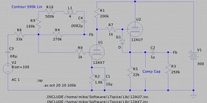
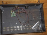
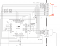
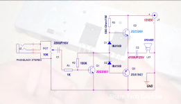
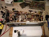
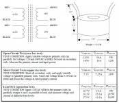
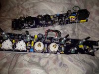
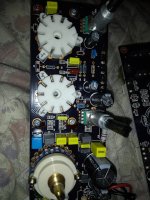
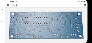
The attached schematic is for the preamp/power amp section of my Lafayette LA-226C stereo receiver, a rebadged Trio WX-400. I recapped it and cleaned it up, and now it sounds very nice, and generally speaking I'm very happy with it. I just want to know more about how this circuit works. Only one channel is shown in the schematic, of course. The rest is mostly not pertinent.

My question stems from what's going on with the cathodes of the output tubes. As you can see, the two cathodes are tied together--the other two 6BQ5s have their cathodes tied into the same node as well. I realize that this is not a particularly unusual practice, especially for amps of this time period. I have a matched quad of JJ EL84s in it, since this means they are all biased together.

What I can't figure out for the life of me is why there are two resistors seemingly forming a voltage divider, with a 9V output going to the grids of the output tubes through those 470kOhm resistors. Is this intended to add a positive bias to the control grid? Or something else? Maybe loading the cathodyne phase inverter?

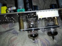
OK, if by some miracle I got that part right, now comes the really confusing part (for me, anyway). On our way down to the cathode resistors, we also see two series tube heaters in parallel with the cathode resistors. So, I assume that with the resistance of the heaters in parallel with the cathode resistors, they are also an important part of biasing the output tubes. Furthermore, I guess this means that the 150V 40uF capacitor serves both to smooth the DC for the filaments of V13 and V14, as well as a cathode bypass cap... I think??? Since it seems like the heaters of V13 and V14 are important for the output tubes' bias, I have made sure that I put healthy tubes here. More on them later.

Finally, to top it all off, maybe everything I just said is basically moot, or not, because where you see the little "K" with a circle around it leads to a little humdinger-type potentiometer (100k, linear) between the +/- of a 5V 0.3A secondary of the power transformer. So I don't know how that affects the bias, if at all. Interestingly enough, the hum balance knob doesn't do anything. The receiver is already absolutely dead silent. (woohoo!)

So how does one calculate the cathode resistance/current through the output tubes?

The reason I ask is because, in addition to my own curiosity, I may eventually like to modify this part of the circuit. It is my understanding that with the tubes biased this way, a matched quad is necessary, and if one of them goes down, the others go with it. For the sake of reliability, it might be nice to change this so each tube, or at least each p-p pair, gets its own cathode resistor (and cap, if necessary). Also, again for the sake of reliability, it would be preferable imo to have the heaters of V13 and V14 out of the circuit. In fact, I've noticed the power transformer runs pretty hot, so maybe in the long run the best move would be to pull V13 and V14 entirely. V13 and V14 comprise the RIAA preamp, which I don't ever intend to use--this receiver doesn't even have a ground screw, and I've got other, better phono preamps anyway. I should also note that I'm not concerned about the resale of the unit, so any (reasonable) mods don't bother me, and shouldn't bother you either 😉

Sorry for being so long winded. Can anybody help??

Attachments

  • Screen Shot 2021-05-03 at 9.28.58 PM.png
    Screen Shot 2021-05-03 at 9.28.58 PM.png
    225.8 KB · Views: 192

PTT6.6 ST-INKY Mounting Hardware

This will be my first Purifi PTT6.5 build project. The plan is to make flush mount bolts to cleanup the lines of the frame/baffle area.

I have no clue whether they matter acoustically. I just find the standard cap screw, or whatever other standard fastener, to be clunky. If there really must be a reason, chalk it up to fabrication warmup exercises.

The goal is to have one completed by this Wed. but I'll give myself a week if it takes that long.

Oh, and it coincidentally looks like something I've seen elsewhere, but I can't quite put my finger on it...

Attachments

  • ST-INKY.jpg
    ST-INKY.jpg
    397.5 KB · Views: 233

Rotary Encoders with Limited travel?

Hello,

Do rotary encoders with limited rotation travel exist? i.e. fixed travel like a pot, but digital output. Or a way to convert a pot's resistance to a digital value?

I'm planning a DSP based audio project, with user adjustable settings (gain, threshold, etc.). The DSP (ADAU1701) supports digital input via rotary encoders. Searching online it appears that all rotary encoders rotate continuously, which would require a display to show the current value (12db). I'd rather the UX react like a pot with fixed travel (say 7 o-clock CW to 5 o-clock) and silkscreen the values on the project chassis.

Any assistance would be appreciated.
Thanks!

should I worry about acoustic coupling?

I just heard about acoustic coupling with subwoofers and now I'm kind of confused. I'm in the process of building a pair of 3 way computer speakers, and because they are computer speakers, the woofers will be pretty close together. (Probably three to four feet?)

I know that acoustic coupling yields a 3 db boost at lower frequencies. Would I have to worry about an overboosted bass response? Would I have to eq this out? I prefer neutrality.

Confused with TU-8600S bypass cap

Just ordered the Elekit TU-8600S. I want to order the cap upgrade next, but not sure which is the correct value. I did some reading here but it seems either .1 uf or .22uf is used for the TU-8600. Is one the correct value and the other a preferred value? Looking at the V-cap ODAM capacitors, just don't know the correct value. Any help appreciated. Thanks 😀

Do the caps need to match? Some offer capacitor matching service, within 5%, 2%, 1%. Not sure if it’s needed.

Yamaha Tyros4 keyboard matrix troubleshooting.

Hi there,
I've got a Yamaha tyros 4 in for repair and the keys seems to have a mind of their own, some keys make sound, some comes out on full volume, some keys remains to sustain long after the key is released and some don't even make sound. Its not consistent meaning the same note does not behave the same all the time.
The keyboard had some issues in the past but it was typical velocity/dead keys and cleaning the rubber contacts solved the problem. However this time it seems this is not the case, I did clean the whole keybed nonetheless and to no surprise it didn't solve the problem. Did a factory reset and it didn't solve the problem either.
So I took out the oscilloscope and probed the scanning pins. Here is what I found:
1. All the pins marked BK (BK00-BK13) shows a nice square wave, with no noise. The 'on' time is longer than the 'off' time.
2. Pins marked with MK does not show a steady square wave but a weird 'spiky' wave - like a weird 'saw-toothish' wave. MK24 was the worst, also on one MK pin(can't remember which one) it showed a square wave superimposed over the wired sawtooth wave.

I couldn't probe around the IC as I would have to disassemble the whole keybed. Was hoping I could get your guys advice on what to look for next and what could be the probable cause for this fault.

Appreciate the help.

Attachments

Can one build a better (non) LS3/5A speaker based on T27s & B110s?

You can buy a brand new Swiss watch costing thousands of pounds which will be no more and quite possibly less accurate than a digital watch from the far East and costing a few tens of pounds - I spent eight years working for a major UK Jeweller 😉

You can buy a pair of late(ish) second-hand Kef T27s and Kef B110s for less than a hundred pounds.

A pair of BBC LS3/5As will cost you hundreds of pounds on the Bay.

Falcon Acoustics are now manufacturing brand new T27s (£144 a pair) and B110s (also £144 a pair) and will sell you a pair of assembled replica LS3/5As with the 15 Ohm FL6/23 crossover for £1,200! A full cabinet kit without speakers but with a crossover will set you back £311.

According to the BBC White Paper (RD1976/29), the LS3/5A cabinet measures 31 cms high by 19 cms wide by 16 cms deep and has a free volume of a little under five litres.

Aside from the obvious requirement that the speaker should accurately reproduce sound, two key BBC design requirements for the LS3/5A were that:

  1. it should be as small as possible consistent with an adequate axial response / frequency characteristic in order to allow use in environments where monitoring on headphones was not satisfactory and yet there wasn't sufficient room for a 'Grade I' monitor - e.g. Outside Broadcast vans.
  2. examples of it should be 100% consistent and interchangeable.
Kef's specification for the B110 suggests a totally enclosed box of five to ten litres should be used.

In a document dated July 1985 describing the construction of a replica LS3/5A, Falcon Acoustics recommended that the depth of the cabinet could usefully be increased from 16 cms to 23cms for a more extended bass.

My question is whether one can build a better sounding small speaker based on the Kef T27 and B110 and if so, what would be its characteristics? I would appreciate it if the discussion could concentrate on just these two drivers and start from the original BBC LS3/5A design. I am interested in hearing views based on the dimensions (e.g. making the cabinet twice as deep -or- twice as deep but triangular), cabinet materials (e.g. braced 25 mm MDF rather than 12 mm birch ply) and (passive) crossover design.

Kef 104/2 speaker question

Hello all,
I bought a replacement capacitor kit for the crossovers in my Kef 104/2 speakers.
I purchased the kit from Falcon Acoustics, and they matched all my old capacitors for value except for two 50u/100v caps. They did not send any 50s, however they did send two 120u/100v. I'm assuming I am supposed to use these in place of the 50u caps. For those of you familiar with these crossovers, the 50u caps are in position C10 on the schematic.
Does anyone know I could plug these in where the 50s were, or that is too much of a value change?
I would/ will take this up with Falcon, however I have read here, and elsewhere, that they are not very good with email replies.
Asking for advice here, thanks in advance.
Dan.

Have i been living a lie

Hi. I purchased a asus H170I-PRO motherboard for £159, was hoping that since it was quite expensive it would have good quality components and good av performance for use as a htpc.
Turned out to be not so good, picture is okay, sound is a little flat and lifeless.
Am looking for any recommendations for motherboards with high quality audio and video cards built in, or is this even possible? What is the best bang for your buck out there.
Or should i get something external, perhaps a usb multichannel dac for the audio. Any recommendations are appreciated. Have a budget of £300, is there any giant killers that have impressed you. Would be prepared to buy second hand if it goes over the budget.
Many thanks

Stuck repairing amp, Please help. Schmatic / Pics inc.

This has been stuck on my bench since before lockdown 1. I was hooked with the student owner saying the previous repair tech he had been to said the amp is beyond economical repair!

https://www.diyaudio.com/forums/attachment.php?attachmentid=944248&stc=1&d=1618919251

Googling W audio, Zenith 3000, prolight.co.uk (importer) got me the operator handbook no schematics so after drawing it up in Kicad, I was curious about one of the heatsink temperature sensors and Googling "90AR3U3" lead to a W_Audio_Zenith_3000_Schematic.PDF for the whole amp! (I just tried to repeat this and failed, cut and past the pdf string instead.)

https://www.diyaudio.com/forums/attachment.php?attachmentid=944249&stc=1&d=1618919251

My KiCAD drawn reverse engineered schematic is V1.0 the other found one for V1.5. To save you playing "spot the difference" they have replaced the triac crowbar with output relay and delay / DC detect circuit and gone to single emitter resistors, the rest of the amp appears to be the same.

On first look after lifting the lid, what jumps out is the absence of isolation pads between output transistors and heat sink. The heat sink is isolated from the case by a thin sheet of fibreglass and is at output potential.

The emitter current share resistors in V1.0 are paralleled pairs of 2W 0R68 and had all "silently" failed open circuit (no sooty skid marks!) is this a metal film failure characteristic?

The only evidence of explosion was a few TO92 with "plasma ejection holes" and charcoaled 1/4W resistors. Removing the PCB from heat sink revealed a few vaporised tracks.

I was hopefully expectant of success after searching and replacing all shorted transistors and diodes and open circuit resistors and missing PCB traces repaired but all to no avail. Both channels refuse to come back to life. I have "come a gutsa" and I am stuck.

Fault finding efforts so far:

With no main output the opamp is open loop so a bit giddy, (proves the clip indicator works!) I've tacked a 100K across pin 1 and 2 to get a test sine wave established between D1 and D2. Dual trace scope (see opening pic) at the e of T11 and T12 can show +ve sine half on T11 and -ve sine half on T12 but only with asymmetrical fine tuning of the power rails (bench supply I'm not poking about with a 3000VA backed PSU) and D7 anode lifted. Once set it is repeatable, turning off/on takes a few seconds for the scope trace to drift back to equilibrium. I've temporarily tacked on a LED to show Mute operating, hardly a second at power up, longer at turn off and I checked, it comes on with a heat gun on the heat sink temp sensor.

How is this deceptively simple circuit of three stacked transistors T11,T13,T15 (T12,T14,T16) per rail supposed to work? I am intrigued by T13 and T14 separating the +-150V (approx with a rail switch) from the +/- 15V small signal operating environment for the opamp to play in.

If you have any advice or fault finding suggestions to help me get this going I will be very grateful. Many thanks.
Mr Chris

Attachments

Apature Accusound 4+4 speaker cable

Recently I bought some of this cable, SH, cheap and without termination. Its silver coated copper in teflon, seems nice and I would like to put some banana connectors on it. Cant really try it on my main system because we escaped to country cottage after earthquake and Covid crisis didnt help. I dont need bi-wire cable so my question is how to terminate it? Can I split that in two by removing transparent coat (model name is printed on it) or just put 4 + 4 together? If anyone had that cable I would be thankful for advice.
APATURE PRODUCTS - DIGITAL VIDEO - DVD - AUDIO - HOME THEATER

Attachments

  • Webp.net-resizeimage.jpg
    Webp.net-resizeimage.jpg
    546.3 KB · Views: 77

Building a Williamson EL34 amplifier

After a failed attempt of a cloned Maplin 4-20 amplifier I thought I would rescue the expensive components and try this Williamson design PCB.

I won't get the schematics until the PCB arrives but it appears to use the 4 x octal sockets for the EL34 output tubes and B9A sockets for the pre-amp and phase splitter tubes.

I'm guessing these will be EF86 and ECC83.

My OPTs are Hammond 1650H.

Attachments

  • s-l1600.jpg
    s-l1600.jpg
    136.8 KB · Views: 1,151

Cost effective Class D Amps for live sound

Hi there,

I'm looking for an amplifier (possibly a complete plate amplifier) to supply about 500W @8Ohms. It needs to take rough handing and transport. This project is a subwoofer, but other projects will probably arise.

What I'd ideally like is something very reliable and reasonable sounding on a fairly low budget. Really, I don't want to spend more than £200-£250 for a fully working unit. Does such a product exist? Or can it be assembled from parts?

I've looked at brands like Dayton audio, but I happen to know their amps were used in some speakers I own, and they've gone wrong twice.

Thanks,
Peter

ZapCo AG1000

Starting this thread for documentation/notes etc.

Amp had blown PS fets, RFP50N06 x 12 all shorted gate to drain.
22 ohm gates, but there is also a single 1/4w 10ohm resistor before the gates from the SG per side. That resistor got a little burned up but still w/i tollerance.
Directly driven from an SG3525A

Nothing seems shorted in the output section at all.

Board seems to be triple layered.

When I first tested the amp, REM did nothing, but the amp did draw 0.5A of current with or without rem attached. I put my scope on the gates of the bad 50N06 and noticed either a PWM drive like I hadn't seen before, or the drive was very wrong looking.

I proceeded to removed all PS fets, and then installed just one IRF3205 into each bank. I may drop those to IRFZ44/48 however.

Still not getting anything out of REM, but the amp is still drawing slightly at 0.02A with or without rem. Most of the pins on the SG3525A are at zero or less than 0.5vDC. Pin15 is seeing only 0.5vDC and so its not getting much supply voltage there either. I may pull this IC especially if it shorted out, not sure yet.

U8 is an LM2903. It sits between REM and, a diode, and 1~2 resistors. Do these voltages seem to be ok?

U8 LM2903
1: 13.35
2: 13.58
3: 12.26
4: 0
5: 12.58
6: 13.35
7: 13.36
8: 14.44

The ONLY other IC in the PS seeing anything more than about 0.5vDC on any IC pins is U2, a LM2703 which has 12.26vDC only on pin 1.

Thank you

Abbott Transistor DC Converter?!?

Hello diy fellows

I have several of very solid build Abbott Transistor DC converter, filter or maybe choke. I could not find any information about this special part and also did not found something with similar specs from Abbott Transistor. Would be really great if you can help me identifying what this thing exactly is.

Here are two pictures. These are shared on my google drive as I do not know how to upload pictures directly from an iPhone.

IMG_0152.jpg - Google Drive

IMG_0147.jpg - Google Drive

Kind Regards and thanks in advance

Phil

First CAD-based loudspeaker project

Hello community,
this is my first post. I built some speakers in the past, but never used any computer simulation to design them.
This time I designed a bass-reflex loudspeaker using Boxsim (Boxsim - Homepage) with Visaton drivers.
I have attached the frequency range that Boxsim computed. As you can see, I did a tradeoff of losing sensitivity for gaining bass response (the 10mH coil in parallel with the 2.2/1.5Ohm resistors is basically a low-shelf filter).
The frequency range, as seen on screen is +/-2dB @ 32Hz-20kHz which seems extremely good for a loudspeaker of this size - But that's all only on screen... Since I have no experience in this domain, I would like to get some approval/criticism from the loudspeaker experts in here. I don't want to build the speaker only to find out that it sucks. Therefore, please go ahead and let me know what you think of this design. All criticism welcome - but please always with rational arguments. Thanks in advance!

For reference, here are the drivers I used:
W 170 S - 4 Ohm | Visaton
G 20 SC - 8 Ohm | Visaton

Attachments

  • 1.PNG
    1.PNG
    56.1 KB · Views: 127
  • 2.PNG
    2.PNG
    15 KB · Views: 131
  • 3.PNG
    3.PNG
    13.8 KB · Views: 126

Variable cathode bias in SSE: 1k Ohm pot?

Hello,

I've been studying others' solutions to setting up different bias conditions for different output tubes, without having to physically replace resistors.

To begin with I was thinking to put a 560 Ohm and 250 Ohm resistor in series to act as the cathode bias, then paralleling the 250 Ohm via a switch in order to select either 810 Ohm (560 + 250) or 560 Ohm so as to create bias conditions for EL34 and KT88 respectively. However I'm not sure this is particularly elegant due to physical space constraints with the PCB.

I notice r_knize has a six position switch that puts one of six resistors in parallel with the one on the board in order to enable bias conditions for most tubes. Nice!

This all looked a bit fiddly though, and I was considering putting in a 1000 Ohm variable resistor or potentiometer (don't really know the difference!) in order to have complete control of the bias conditions rather than be limited to discrete values.

Am I completely bonkers to consider this?

amp distorting

View attachment 946563


Hi and thanks for reading. I have built this amplifier, please see attached circuit diagram. It is working fine the midrange and treble are good but whenever the amplifier tries to reproduce a low bass note i get a lot of distortion.
What do you think is wrong can you please advise.

Attachments

  • vlcsnap-2021-04-26-17h39m52s703.png
    vlcsnap-2021-04-26-17h39m52s703.png
    372.4 KB · Views: 353

Recommendation for 5-10W amp.

Hi,

Been looking around to build a nice sounding 5W amp, I have the ACA which I truly enjoy so this leads to for wanting more of Mr Pass design.

I bought some components to built the F5 but this will be later, a fall project. I have a whole bunch of NOS TO3 lateral mosfet that I'd like to use soon.

Looking for some recommendation, I heard that sound wise the Aleph 3 sounds like the ACA, makes sense ? I'd like to avoid building an amp that sounds extremely similar to the ACA which I already own, I'd like to taste a 'different wine' while building a Pass design.

I'm now looking into the Zen but a low power version (+24V-Gnd) to get about 5W. Any other recommendation are welcome.

My speakers are MLTL with FE206E and my music taste is mainly Blues, Jazz and Classic.

I own a few low power tube amps, all SE except for one.

LATEST INFO : Juma came up with a design, please see post no. 217.

Thanks for your time.
Eric

Bias current problem

Hi, I couldn't drop the bias current less than 6mv over output resistor for only one channel. I've tried for weeks 🙂 When I want to adjust semipot it drop the 6mv and increase again. Min value is 6mv (about 90ma or more) over 0.067 ohm resistor (R196). The other channel can drop to 1mv or less.

I changed all elect. caps and most of transistors. (not earlier stage of amp. and not power output transistor Q139,Q141). But, all looks like ok. resistors are ok.
After weeks I want to ask here. I couldn't solve 🙂 Any idea will be very helpfull. note that there is no problem in sound! I add the schematic here;

Ekran görüntüsü 2021-05-02 141652.jpg

Using the second input for L,R with Sub EQ

Hi I have a 7.3.0 set up and it is currently using a Mini DSP to time align and EQ my three subs,

As I have no way of crossing over the low frequencies that go to the mains I was thinking of simply using the second input from L or R (or both ?) to input 2

I can put a roll off on the input as my subs go up to 70Hz and my fronts go down to 30Hz, So I was thinking of adding everything below 35Hz to the Mini DSP and subs

So I was thinking of taking the analogue out from the processor and 'Y' cabling to both the power amp and the Mini DSP for L, R or both

My question is can I build a cable that mixed the L,R channels and shared the earth on the RCA without corrupting channel seperation or just use, L or R ?

LMS 3.71 Gated Response

Hello everyone. I hope you are all doing fine. I have LEAP and LMS from LinearX co that does not exist anymore due to passing away of its founder.
Now I am noticing that even though all calibration passes with no failure, the gated measurements are not what they used to be - it is very low to almost just room noise. I have tried installing it on a different slot and even with several calibration, resulted no change.

Could you suggest anything?

PS. The regular sweep is working fine and is correct!

Thanks,

Vilic.

FS: Modified Behringer DCX2496 3-Way Crossover/Equalizer - may need repair

This DCX2496 was included with Emerald Physics open baffle speakers. I spend over $1000 having Ric Schultz upgrade it with new input and output circuitry including all RCA jacks. He also upgraded ADC and DAC chips, Vregs, Power supplies, etc. Very musical and analog sounding!

Recently it started struggling to boot up with LEDs flashing rapidly until it completed the startup in 2-3 minutes. I usually left it powered up during which time it never had this problem.

The asking price for a DCX2496 modified by Ric Schultz without any problems has been as much as $1500. I prefer that it be sold to someone who understands this Behringer model inside and out. Includes manual and all my downloaded information about the DCX2496. It will never be worth less than the value of the pair of Lundahl transformers in the input circuit. Moderate scuffing on top and bottom, but front is clean with clear protective plastic still on displays.

$300obo plus shipping.

Attachments

  • Behringer w-Truth.jpg
    Behringer w-Truth.jpg
    142.8 KB · Views: 228
  • Behringer back mod.jpg
    Behringer back mod.jpg
    126.6 KB · Views: 170
  • Behringer mod open full.jpg
    Behringer mod open full.jpg
    315.5 KB · Views: 232
  • Behringer mod lundahl.jpg
    Behringer mod lundahl.jpg
    166.2 KB · Views: 179
  • Behringer mod PS.jpg
    Behringer mod PS.jpg
    207.1 KB · Views: 175
  • Behringer front routing.jpg
    Behringer front routing.jpg
    78.3 KB · Views: 136
  • Behringer front xover.jpg
    Behringer front xover.jpg
    108.6 KB · Views: 151

Greeting from the PNW in the US

Greetings from the PNW of the USA. Justin here. Started dipping my toes into higher level audio a few years ago and in the last several months started delving further into hi-fi. Mostly headphones and near field listening. Started out with a Hidiz AP and Shure SE215's. Added a PS Audio Sprout, Grado SR225e's, Music Hall turntable with upgraded Nagaoka MP 110 cartridge, Martin Logan Grotto sub, and some older Mission bookshelf speakers.

The DIY bug has bitten me and I just "built" a pair of Mark Audio Tozzi One near field speakers and added a Raspberry Pi4 with Volumio. Now onto a Pete Millet NuHybrid headphone amp as my first diy amp build. If all goes well plans include an Amp Camp Amp and a diy electrostatic headphone amp and... Lol.

Looking forward to learning and contributing. Cheers.

Need help with OB design - cheap, cheap, cheap

Hi All, I never had much interest in OB speakers, but to be fair, I never really listened to them. Well, this past weekend was the AK fest and I sat and listened to the Salk Audio OBs for a couple hours. Now I want to build a pair with stuff I have laying about. So, what are the critical specs I need to look for in the drivers? I have a lot of drivers and would rather go about this with some clarity of thought vs. just trying everything I have to see what works.

Here is what I have so far.

TWEETER:

The old but wonderful Philips tweeter. The back is enclosed so not really OB. Here is 1. the spec sheet and 2. a crossover designed for them.

http://www.troelsgravesen.dk/WWDT_files/ad0160.pdf

WWDT (at the bottom of the page)


MIDS:

The Parts Express PA130 5" midrange driver.... here is the spec sheet

http://www.parts-express.com/pdf/295-010s.pdf


WOOFERS:

And this might work for the woof - I have 4 of them. - CERWIN VEGA S-10.8 10" 8 OHM 400W STEALTH WOOFER

This is all I could find on them

• Woofer Size: 10".
• Frequency Response: 40Hz -500Hz.
• Power Handling: 200 watts RMS (400 watts Maximum).
• Sensitivity (2.83V @ 1 meter): 93dB.
• Impedance: 8 ohm.
• Mounting Diameter: 9.0" (22.86 cm.).

I posted this in the Fun OB thread but then realized that I was highjacking the thread and so I am starting this thread.

Panomaniac posted a number of posts about the RROW and that makes a lot of sense. But, I don't know enough about crossover design to figure a crossover out.

P.S., this is all stuff I have laying around for years if you are wondering why I would chose these componants.

Cheers.

Attachments

  • wwdt-3.jpg
    wwdt-3.jpg
    59.9 KB · Views: 563
  • 295-010_s.jpg
    295-010_s.jpg
    13.2 KB · Views: 547
  • S-10_8.jpg
    S-10_8.jpg
    24.4 KB · Views: 525

Waveguided tweeter questions.

Hi folks,

Due to an incoming project with a waveguided DX25 tweeter within a WG148 Visaton, I'm asking myself the following questions.

-The speaker will be wide baffle. Will the width act as expansion of the waveguide, bringing it's effectiveness further to lower frequencies?
-Is it necessary/beneficial to offset the tweeter despite the waveguide to fight diffractions?


Best regards,
Alexander

New 45/2A3 amp power supply question

Hi All.

I'm starting a new 45/2A3 build soon and would like your opinions on a power supply that I have been playing with. I have attached A PSUD2 screenshot for your consideration. It will be optimized for 45, as I have a couple of nice pairs, but I would like to use 2A3 in it as well. I could do this by using a different rectifier when I use 2A3, or I could vary cathode resisters with a switch or both. Any comments or advice would be appreciated.

Attachments

  • 45.jpg
    45.jpg
    536.3 KB · Views: 671

One of these days

Power On since a log period of not use my Tek 7L12 Spectrum analyzer, and bang a problem. I couldn't turn the nice coarse tuning dial, it is barely move and jammed...

Time to open up the beast, used to calibrate and repair these guys 35 years ago... These Tek modules are so dense that it is not a work in the park to work inside them, and the spectrum analyzer are the worst!

I had to completly removed the front panel and the thousand buttons and dial, and the IF module to be able to pry open the front section wide enough to extract the frequency dial assy. Guess what I found? a little custom gear was unglued and cam apart. It was no longer turning the mechanical dial and YIG tuning pot...

Put some glue, let it tried and put it back to try. But surprise! naturally it was not working fine, dial was still difficult to rotate at some position, and jam at others. Removed it and using a magnification glass look at the little gear teeth, bingo some where slightly bent, and some other where not straight. Using a fine plier I straighten and realigned the incorrect teeth. Put it back and Voila! working like a charm again.

Attachments

  • IMG_20210502_235810.jpg
    IMG_20210502_235810.jpg
    375.8 KB · Views: 106
  • IMG_20210502_235806.jpg
    IMG_20210502_235806.jpg
    585.3 KB · Views: 98

6SN7 + 6SL7 suggested combination for Willsenton R8

Hello.
I have bought a Willsenton R8 amplifier.
I will use Genalex Gold Lion KT88 reissue power tubes and I'd like to know what kind of 6SN7 (x3) + 6SL7 (x2) shuold you reccomend me not expending more money in tubes than in the amp itself.

I have RCA 6SN7GTB that I could use... what 6SL7 for those?

Attached you will find schematic if it helps
thank you.

FS: Pair of Tweeters for Sonus Faber Cremona

Hello
I have sold my SF Cremona and I had some spare parts that the new owner hasn't bought... and I don't need them any longer.

For sale a pair of Sonus Faber Cremona tweeters (ref: TWE3001) valid for floorstanders and bookshelf (Cremona Auditor)

They are absolutely in new condition. Never used not measured.
Boxes opened just to take pictures.

Retail price is 190€ each. I would let them go for 200€ shipped to EU.

I have opened an auction at ebay, so, if interested, this is your chance.
Tweeters Sonus Faber Cremona TWE03001 (pareja) | eBay

An externally hosted image should be here but it was not working when we last tested it.

An externally hosted image should be here but it was not working when we last tested it.

An externally hosted image should be here but it was not working when we last tested it.

An externally hosted image should be here but it was not working when we last tested it.

OTL power supply advice

Hi,

I have built the OTL amp described in the thread:

HTML:
https://www.diyaudio.com/forums/tubes-valves/189282-vacuum-tube-otl-power-amp.html

As i was building it and fitting into a case all seemed fine but now it sounds awful at even moderate volume. I am a newbie to valve amps but i think the problem is the power supply, which is basically:

115v-0-115v toroid - bridge rectifier (1.2kv, 16A UF soft recovery) - 4700uf 250v in both the +ve and -ve rails and 1000uf 400v between the rails. This provides +150v / -150v.

When i turn the PS on i get +-150v at the final cap as expected but then when i turn the 6C33C heaters on the PS output drops to approx +- 40v with only 9v across the cathode resistors (was about 40v when the amp was working OK).

If i pull the tubes on one channel the voltages improve slightly.

Im guessing its the caps (Evox Rifa PEH169's) which were NOS are failing after only a couple of months of use.

Would be grateful for any thoughts / advice.

Thanks
Gav

Amp outputs for LG 55um7000 (TV) internal speakers

The LG 55UM7000PLC internal speakers are chip amp powered from the board, and my question is if this is a traditional amp - speaker setup, or if it is something else.

My reason for asking is that the TV lacks variable line out, or any analog audio output for that matter and I wanted to get a couple of rear surround channels out of it.

The way I want to accomplish this is by connecting the +left and +right from the internal speakers to the primary side of a 15kOhm 1:1 line transformer after having taken down the speaker level to line level using one 10kOhm resistor on each speaker level feed.

On the secondary side of the line transformer I choose one lead as ground and the other as signal and connect these to an external amp to get the rear surround, these will then only put out the difference between the two front channels.

The problem is that all I get is noise in the rear surround channel, so I suspect there is something going on with the internal amps output to the internal speakers, of which I get my line transformer inputs as described above.

Any ideas or thoughts on why this might be?

Please don't suggest getting an external surround receiver, this is a diy forum after all 🙂

Measurements from MTM with tweeter waveguide

Here are a couple sets of measurements I obtained using SoundQueasy to measure the response of my latest speaker project. It's really an extensive overhaul of a previous design, using the same drivers but modifying the cabinets and adding an MCM waveguide to the tweeter. The drivers are oldies but goodies: ScanSpeak d2900-9300 textile tweeter, and two Vifa 5.5" P13WH-00-08 woofers. These are the same drivers Olson used in his original Ariel speaker design some of you may remember. For historical reasons my two woofers are rather widely spaced (sorry, I have no photo with me as I write this). Given the recent interest in waveguide-terminated tweeters I thought the measurements might be of interest to someone anyway.

The top set shows the total SPL, the woofers with their crossover in place, and the tweeter with its crossover in place. The slight downward tilt in the response was done on purpose because I didn't want an overly bright response. These graphs do not include any nearfield woofer measurements to extend the results to lower frequencies, so ignore the low frequency rolloff. (In case the scales are hard to read: there are 5 dB between neighboring pairs of horizontal grid lines.)

The lower set of measurements is from on axis (0 degrees) and then increasingly off axis in 15 degree increments (15, 30, and 45 degrees). All measurements were taken at about 1 meter, and at the height of the tweeter.

The glitch in the high frequency response around 10 KHz is a bit smaller in the other speaker, but otherwise the responses of the two speakers are nearly identical. Comparing waveguides I think I might have made one waveguide VERY slightly deeper than the other. I've verified by adding pieces of tape to the waveguide that little tiny changes in the tweeter's immediate environment induce significant changes in that 10 KHz range.

In spite of the glitch I was pleased by the controlled off-axis rolloff since that was one of my main design goals. Now I'll just have to learn how to make better use of SE's crossover optimization tools. I came up with these crossovers the old fashioned way: tweak-measure-tweak-measure...

Few

MTM_waveguide.jpg

Potentiometers for the elektuur Preamp

I almost sourced all my components to build the elektuur Preamp. I just need the potentiometers dat are listed in the article.

- 10k log potentiometer: Bourns, Spectrol,...
- 10k log stereo potentiometer: Alps RKGA2-10K AX2

I didn't find that specific Alps type potentiometer and the Bourns, Spectrol don't specify a part number.

Can somebody suggest high quality potentiometers dat I can use in this preamp.

The article itself is in februari 1987 of elektuur.

EQP-KT Valve EQ mod advice please

I'm trying to improve the sound of this EQ but there are no schematics. Anyone have a clue what should be replaced for improvement? I'm mainly interested in the path of the valves. Thanks

Attachments

  • IMG_20210428_235412066.jpg
    IMG_20210428_235412066.jpg
    690.6 KB · Views: 469
  • IMG_20210428_235420670.jpg
    IMG_20210428_235420670.jpg
    636.7 KB · Views: 454
  • IMG_20210428_235424230.jpg
    IMG_20210428_235424230.jpg
    602.6 KB · Views: 421
  • IMG_20210428_235427780.jpg
    IMG_20210428_235427780.jpg
    587.6 KB · Views: 413
  • IMG_20210428_235432178.jpg
    IMG_20210428_235432178.jpg
    642 KB · Views: 493
  • IMG_20210428_235438244.jpg
    IMG_20210428_235438244.jpg
    649.5 KB · Views: 322
  • IMG_20210428_235447588.jpg
    IMG_20210428_235447588.jpg
    571.8 KB · Views: 357
  • IMG_20210428_235455293.jpg
    IMG_20210428_235455293.jpg
    529.2 KB · Views: 406

Arcam Alpha cd7se powering on and off while playing

I found a helpful thread here to change the Sony kss-240a laser when it started skipping all the time and cleaning wasn't helping.

First impressions were great, no more skipping, then after about 3 minutes the power tripped off (including the main green power light) then came back again. So it sounds good now but only lasts a few minutes before it trips. Anything I might check? I tried a different power source already, tried reseating the ribbon cables. Would be delighted to get it working again. My electronics skills are limited but I do have a multitester.

When I plugged it back in, in my haste to check the result of changing the laser, the power button was already on whereas I would normally be careful to check first. Could the elderly circuits have suffered from that initial surge?

Any suggestions much appreciated!

Cheers,

Dave

VU meter works on preamp input put but not on output....

I have a led vu meter based on the KA2284 IC. If I connect it to the preamp input it works fine but as soon as I connect it to the output of the preamp the signal level of the output drops drastically. The preamp is based on NE5532 opamp. Im a total novice, I'm guessing it's to do with impedance matching but can any experts help me diagnose the issue? Preamp board front/rear and vu meter images attached....

Attachments

  • Screenshot_20210429-140438_eBay.jpg
    Screenshot_20210429-140438_eBay.jpg
    225.8 KB · Views: 195
  • Screenshot_20210422-114354_eBay.jpg
    Screenshot_20210422-114354_eBay.jpg
    861.6 KB · Views: 169
  • Screenshot_20210422-114343_eBay.jpg
    Screenshot_20210422-114343_eBay.jpg
    332.6 KB · Views: 199
Projects by fanatics, for fanatics
Get answers and advice for everyone wanting to learn the art of audio.
Join the Community
507,774
Members
7,888,071
Messages

Filter

Forum Statistics

Threads
406,220
Messages
7,888,071
Members
507,774
Latest member
pete2000