Looking for some help with Adcom gfa-5503

So I just bought an adcom 5503 amplifier. It does work and sound ok but it runs very hot even while on very low levels. Also there is a horrible buzz sound coming from the toroidal power supply.
First off ill tell you about the temps. All 3 channels are within 5 degrees F of 125. Now it does take a few hours to get that hot but it still does. I started with a cold amp the other day and played music at a pretty decent volume and it didn't get that hot, so it is something that is taking a while to do. From what I have read its probably a slightly high bias maybe?
Now about the buzzing toroid. It is a pretty decent buzz coming from the front of the amp. It is affected by turning on my av receiver. As in it will get loud then go back down when I hit the power. I tried a 3 to 2 prong adapter to rule out ground issues and it made no difference. Also there is a hiss in my tweeters that sounds just like the buzz.
Another thing that I noticed was that the power light doesn't stay on long after the power is turned off. I have a 555 Adcom that the power light will stay light for like 30 seconds before going out. The 5503 might stay on for 3-4 seconds. Could this mean there is a bad capacitor? And maybe it is causing the toroid to buzz? Just a thought.
I did measure the dc offset and the L/C/R measures 9.4/14.4/27 mv. My plans were to tear it down and look over the components for obvious damage, bad solder joints and maybe take the big capacitors out and take them to be tested. I will clean everything up and set the bias and dc offset and see what the result is. Is there a way to test the toroidal transformer? Or if I took it with the caps maybe a shop could test it? Any ideas what's going on here? Any help would be appreciated. Thanks mike.

Transformers in the Leak ST50 for a project

Hello,

I just aquired a Leak stereo 50 chassis thats a bit raped and beat but, so far the output transformers check out to be all good, all coils intact with reasonable DMM readings.

The power transformer however is going to need some more research on my part to see if it will be usable for a stereo instrument tube amp project right up and coming.

For reasons that elude me totally, I've come across a couple of schematics that on one hand will show the HT voltages as 340-0-340 and another of 360-0-360 but then show a B+ of 408volts with 380 volts arriving at the plates of the EL34 power tubes. The rectifier is a GZ34 so my math tells me that the ballpark B+ should be around 340 x 1.3 = 442 volts coming out of pin 8 of the GZ34 rectifier. And the articles around (which aren't too many) all do claim plate voltage of a relatively low 380v on the EL34 plates. For my coming project I'm looking to get a higher voltage on the EL34's, maybe more around 425-450. It looks like the original Mullard Blackburn tubes are all there including all the 12ax7's and even the GZ34. That was a nice surprise when I found the etched Mullard codes and looked up how to read them. I suspect those EL34's will be happy with plate voltages in the range I'm looking to place on them
But, as good as I thought I was at digging up specs, I failed to find any definitive specifications on the rated voltages and V/A's of the coils in the Leak Stereo 50 power transformer. I did find a general spec guide that was helpful with with the OT's, showing primary impedances and dcr coil ohms but nothing very deep on the Power transformer which is Model 8191 as stamped on the bottom of the power transformer.
If anyone can lead me to a real source for the electrical specs on this, that would be great. Of course, I will take the PT out, input some wall voltage and make voltage measurements on all the secondary coils but, it sure would be nice to see some manufaturers ratings on these as they were intended to be.
Thanks for your time and all input welcome!
Best,
Phil Donovan

FS: Transformers for volume contorl (TVC), 24 steps of secondary

Sold! Transformers for volume control (TVC), 24 steps of secondary

Sold


Up for sale excellent input transformers for transformer volume control (TVC), Audio Music, AMT.
You can spotting up on these transformers in devices for 3-6K, with googling.

600/1200 >10K, 24 steps of secondary coil

Never used.

Some pics with analyzer>>>
(analyzer is not part of an offer).

Questions, more info on request, any time.

Transformers will be packed carefully with international tracking across all distance.
Sending from Ukraine. Payment by direct wire transfer.

FREE shipping across EU/UK.

--
See also other our items:

- Transformers UTC 2x A-18, 2x A-15, 4x A-22, Northern Electric R20536A 5:1
Set of 9 excellent UTC transformers, A-15, A-18, A-22, NE
- Vintage detented/non-detented attenuators Daven, Shalco,Clarostat, Langevin, USA
FS: Set of 7 excellent vintage attenuators Daven Shalco Langevin Clarostat
- other small items
FS: Few different itmes - NEC relays, Meters, Caps, Cam, Cable

Attachments

  • 1 main.jpg
    1 main.jpg
    461.9 KB · Views: 658
  • Копия lat .JPG
    Копия lat .JPG
    941.9 KB · Views: 652
  • Копия top clamp 2.JPG
    Копия top clamp 2.JPG
    890 KB · Views: 629
  • IMG_5403.jpg
    IMG_5403.jpg
    458.1 KB · Views: 616
  • IMG_5402.jpg
    IMG_5402.jpg
    449 KB · Views: 597
  • IMG_5401.jpg
    IMG_5401.jpg
    413.4 KB · Views: 206

Marshall VBA400

Hi


I would greatly appreciate some help with this amp. The High Voltage toroid transformer has blown. The original transformer is from Toriod International Ltd with P/N TI-65765B. I could not source the exact transformer. I would like to know what are the secondary voltages so that I can source locally. There are three wires on the secondary. Red, Black and Orange. I guess the black is the center tap. Pls assist.


Thanks

Attachments

Hartke HA3500

Hi


I have another issue with this amp. The amp is functioning alright, it is only when I turn on the "EQ". This is constant crackling and popping noise. I have replaced all the electrolytic and non electrolytic caps and the ICs as well in the EQ circuit, but the noise is still there. Can it be due to the EQ faders or can dry joint cause this problem. Please assist.


Thanks

Rainy day ‘educational’ speaker project.

Today has been a wet Saturday! I therefore decided to build a pair of speakers with my 5 years old son that I can use at school when teaching sound, magnetism and electricity.

The components:
1) Pioneer TSG-400 coaxial car speakers - £20 a pair from Halfords.
2) 2 plastic lunch boxes from Wilco’s (£2 each).
3) A few sundries.
4) stuffing from an old duvet.

It took a couple of hours for us to ‘build’ these - the second was much quicker that the first. I did the bits that involved a craft knife!

I built them to use at school so that the children could actually see (hence transparent enclosure) how a speaker works. All the workings are mounted in the lunch box lid so that they can be easily taken apart and even run open baffle to show the children what difference an enclosure makes and to investigate why this might be.

After a bit of experimentation and run-in I thought they sound better than expected, if a bit thin. As luck would have it, we have just replaced a duvet in the house so I put a couple of roles of the stuffing in each speaker. The net result is that they sound surprisingly good, if still not exactly full range - pretty clear mids/top but limited bass extension. TBF, fed by an Arcam CD player and Arcam A18 amp I’m quite pleased, especially for the £30 cost all in - considerably better than a most Bluetooth speakers anyway and quite a nice soundstage when on a desk.

I’m not suggesting that everyone rush out and build this but, if you have a few idle moments, a spare £30 and want something that you could involve your child/children with, it’s worth a go.

I have added a few pictures from start to finish.

Attachments

  • E612EF74-FD38-4613-B6D2-64220DF7B796.jpg
    E612EF74-FD38-4613-B6D2-64220DF7B796.jpg
    463.4 KB · Views: 218
  • 69F0E2F5-1A2F-42A6-A647-F4B17F06672D.jpg
    69F0E2F5-1A2F-42A6-A647-F4B17F06672D.jpg
    570.6 KB · Views: 222
  • C7655916-024A-4482-A36E-2E74DEF14312.jpg
    C7655916-024A-4482-A36E-2E74DEF14312.jpg
    642.5 KB · Views: 209
  • s.jpg
    s.jpg
    658.9 KB · Views: 180

FS: Jordan jxr6 50 mm drivers- used pair $60 shipped

Sold: Jordan jxr6 50 mm drivers- used pair $60 shipped

I have a pair of these that I used for awhile. They are marvelous small drivers. One driver has a 1/8" dimple on the center dome. The faceplates have scratches on them. Not the prettiest, but they work very well.
Picture:
https://www.audiocircle.com/image.php?id=224333
A little info:
DIY Paradise - Jordan
$120 ea. when new, asking $60 for both shipped to cont. US.
A good opportunity to try these classic drivers out at minimal cost!
Thanks for having a look.

Sony GX10es transformer workaround

I've got a Sony GX10es on the bench and one of the secondary windings has gone dead. But it is one of the smaller supplies so I'm confident I can do a workaround. (Pretty rare failure in my experience but that seems to be it, coil measures open on my meter)

I could find another transformer with the right ratio and add it in, or install a couple voltage regulators and run them off the main rails. I'm thinking the second approach would be better.

I've attached a schematic with relevant parts highlighted.

Missing DC voltages are 21.7V. An AC voltage is missing as well, for the ac off detection. I brought sound back by pulling the rectifier and hooking up a couple DC bench supplies. Had to jump the back of D801 to the winding for the AC detection, the dead winding still seemed to pass enough voltage to make it work but I could adapt the circuit to run it off the main windings.


I feel like I have this under control, but was wondering what people here think.


Something like this for the regulators? 20V should be close enough? MC78M20CTG
Just need a negative one too.

Attachments

  • gx10es.PNG
    gx10es.PNG
    293.4 KB · Views: 103

Phoenix Gold Tantrum 500.2

I have two of these amps on my bench currently, and both seem to have exactly the same problem - that would be failed output FETs.

Amp 1 is using IRF540 (NON N designation)
Amp 2 is using FB41N150

Both are using 10ohm gates at outputs
MPAS06 and MPSA56 drivers.

I've read in another thread that commonly these amps get upgraded to different outputs, IRF540N, FB41N150, FDP42AN15A0, or IPP200N15N3G. Some of these changes require a different GATE resistor.

Also Im having trouble identifying which OpAmp controls the bias, as I understand one which is out of spec could cause bias issues and sounds like probably should be replaced.

I clipped off all the bad outputs, leaving some which seemed to still be testing OK, and got both amps to power on without any further issue.


Can someone help me with correct component selection/combination for the output FETs, gates, and Bias OpAmp?

AER Compact 60 amplifier overheating problem

I am currently looking at this amp after being told that it suffers from cutting out after an hour or so. I cannot get hold of a service manual for it so it's a case of running several tests and looking around to see what's going on inside.

On closer inspection, I found that the bleed resistor had gone open circuit. Not that this would affect the actual operation of the amp. I put a new one in and it burnt out straight away. Not sure why this is happening.

I also found that the main amplifier chip on the board attached to a large heatsink is a TDA7294. This chip has a thermal overload protection built in so I think this is what is operating and causing the amp to cut the sound output (the power light stays on when it shuts down).

I could not get the amp to shut down when I was running my hifi tuner into it for well over 4 hours yesterday. It only shuts down when a guitar is playing through it.

I am thinking of replacing the TDA7294 as I suspect it might be damaged and thus activating its protection circuit prematurely. My friend says that his band member has exactly the same amp and his does not run as hot as my friend's one after an hour of playing.

Any ideas on this one?

Reduced Output From One Speaker

I have a problem with a previously enjoyed set of ML ESL's I purchased a little while ago. When I first noticed reduced output from one of my speakers I got on Google and noticed some posts about reduced output from the ESL panels and the steps you could follow to correct that. In fact, when I contacted ML service the instructions they sent me focused solely on the ESL panel. After following those instructions with no results I broke out REW and my calibrated mic. To my surprise it was one woofer that was 6db lower at 200hz. As you can see in the attached sweep below I do indeed have a woofer issue. Now I'm left with determining all the potential causes of this issue and then see if it's within my skillset to correct it. If you have an idea for a possible cause of this issue your opinion is welcome.

Regards,
Dan

attachment.php

Attachments

  • 500Test.jpg
    500Test.jpg
    169.4 KB · Views: 236

vsat of EF output stage

hi Guys ,
what should be the typical vsat for EF type output stage say for a 200W amp running on 4ohms , and it is possible to reduce the vsat by increasing the base current ?
I am using type a configuration in my amp and i generally get a vsat of around 5V for 200W at 4ohms which increases to around 8-9V for 400W at 4ohms , is it possible to reduce the vsat ?

Attachments

  • dddddd.jpg
    dddddd.jpg
    40.4 KB · Views: 237

The best amplifier I have built so far

Now I've built a few.

My first was JLH 80W MOS-FET amp which really blew my socks off back in the 1990s.

That was only beaten a few years ago when I built a Pass Aleph 4. Now that is seriously nice amplifier.

But, recently I built a Pass Aleph J. Although not as powerful, it is just so sweet to listen to compared to the Aleph 4.

Last week I finished a Williamson 5-20 EL34 amplifier which, to my ears knocks the socks off all of the others.

The Williamson just has so much more depth to its sound and far more control of the deep bass all the way through to the high treble.

Tube phono pre-amp PCB Shure M-65 VS EAR 834

Hello All,


I was looking into building a 'kit' tube based phono pre-amp. I wanted to go with a a proven circuit design as I know that it is critical with parts and how you place them since the gain is much higher than in a line stage and hence the reason why I wanted to go with a PCB for my first time out. This is for a Moving Magnet application and will stay so as I have no interest in moving coil cartridges.


Looking on-line and on Ebay, it seems that there are numerous PCB's made for two main styles of tube based phono preamps. One is based on the Shure M-65 which is shown here:


MM RIAA Tube Phono Amplifier Board Bare PCB base on America SHURE M65 Circuit | eBay


And the other is based on the EAR-834 preamp and that is here:


E834 RIAA MM Tube phono amplifier PCB Turntable preamp Base on EAR834 Circuit[C1 | eBay


Both PCB's are around the same price, but that is irrelevant as I am more interested in the sound quality. So for those in the know and perhaps built one or both of these either of these PCB's before, which one sounds better?


From the look of it, the M65 seems simpler and uses 1 less tube. However, I do see some sand in the mix, but it could be just regulators for the tube filaments. I just know that the PCB doesn't quite match the schematic for the actual Shure M-65. The 834 definitely looks more complex as it uses 3 tubes as opposed to two, but I don't see any sand in the design.


So it boils down to what is accepted as a better design. While I am interested in input on those that have actually used these PCB variants, I am also interested in those that have used both of the original preamps or even compared the originals to these PCB variants.


Thank you,
Geo

desktop speaker with Markaudio Alpair5

I wanted to present *) a design I made with the smallest Markaudio, the Alpair 5. Despite the design intent of the Alpair5 as a midtweeter, I decided to make a full range speaker for next to the PC. I made a TL enclosure (1:10 taper, driver at 1/3rd of the line) for it to make it truely full range.

176086d1276431024-desktop-speaker-markaudio-alpair5-ga-voor-goud.jpg


and the result: truely amazing. the level of detail in the high of the Alpair5 is stunning, better than many tweeters. I have applied a notch filter (0.05mH, 27ohm, 3.3uF) to tame the 10-14kHz area (now it is flat within a few dB measured under 15°) but if you listen a bit more off axis this might not be neccesary. And the bass? nice and clean, deep enough (extends down to 60Hz, TL is tuned at 55Hz) for most music. I use them at my PC powered with a T-Amp, and I noticed I listen to music a lot more now...


*) this is also published in the dutch elektor magazine; I waited with posting it here until the mag hit the shelfs

Attachments

NUG

Hello from Annapolis Maryland.


I'm here to learn more about electronic - particularly, my old Stereo gear (Pioneer vintage mid 80's stuff.) I still hve my Pioneer A-77X (which is currently not well), my Pioneer Tuner F-99X, and Denon turn table.


Hoping to learn more about electronic components, how to test them, and how to trouble shoot issues.

Kenwood KR 2010 bias adjustment

Hello. I acquired a Kenwood KR 2010 receiver (year 1976) in very good aesthetic and working condition.
But I have found that the bias current of the power stage is not similar on both channels.
Channel R - 8 mv (12mA) and channel L- 19mv (28 mA).
The problem is that it does not have an adjustment potentiometer.
How do I adjust it?
Can a potentiometer be inserted for adjustment?
Thank you.

Attachments

  • Kenwood KR 2010.png
    Kenwood KR 2010.png
    459.8 KB · Views: 423

DIY PVC Bluetooth Speaker

I'm fairly new to making speaker enclosures, I've made a couple for past vehicles that have worked very well, and I've been looking at making a portable speaker for a while.

Basically I watched a YouTube video where someone took an 8" wide PVC pipe and made a speaker, but I didn't much like how it was built, tons of air leaks and poor build quality.

The design I'm looking at is similar to what was done on this post: https://www.diyaudio.com/forums/subwoofers/219481-pvc-enclosure-tips.html

I've been looking at what speaker might be best for this and looked through forum posts for ideas, but nothing really stood out as being helpful, the only thing I'm really struggling to figure out is what type of speaker is best, I plan on going with the 8" pipe and lining it with cork, length would be determined by the speaker type, I was looking at 6.5" full range speakers but I'm not sure this is the best option. As for ported / sealed I was thinking I'd try my luck with a totally sealed enclosure, as I feel that would be easiest.

It might be a long shot and I might be in over my head but I thought I'd see what experiences / inputs you might have, thanks!

Randall RGT 100HT Tube Amp Repair and Schematic

For those of you who may be fans of the somewhat rare Randall tube amps of the late 80's, I thought I would share my experience with repairing an RGT 100 HT made in 1989. I purchased the it on eBay as a non-working amp with the intention of repairing and reselling it (although more for the challenge of figuring out what was wrong and fixing it). I apologize in advance for the length of this post, but there is very little information on these amps available on the web so I thought I would share what I found in detail.

When I received the amp it was in fantastic physical condition, with barely any signs of wear, although it weighed a ton (this is the rack version of the amp). I plugged in the amp and immediately noticed one of the four power tubes red plating. I turned the amp off and removed the outer chassis to get a good look at the tubes (picture of chassis with exposed boards below). Someone had been through the amp boards previously because there are green dot markings next to some components and one of the capacitors on the main board had been replaced (circled in red, left side of photo). Anyway, not only was one of the four 6L6GC's (the one that had red plated) completely clouded at the top, but so was the 12AT7 PI tube (pictures of both tubes below). I removed all four 6L6's and the 12AT7, replaced the 12AT7 and plugged a new 6L6 into the same socket as the red plating 6L6. Both tubes began to red plate. I then moved the power tube to each of the other four sockets and it red plated in each position.

At this point, I realized that something was causing an excessive amount of current to pass through the PI and all the power tubes. My first thought was that there was insufficient quiescent bias on the power tube grids so I looked for a schematic on the web. I only found two versions of the schematic that were extremely difficult to read. So I took the step of redrawing the schematic in Illustrator to make it easier for me to do the troubleshooting. I have attached a copy of the reworked schematic (with permission to recopy for non-commercial purposes). I think it's correct, but it might contain typos so use it at your own risk (I could not determine the value of the cathode resistor for the PI because it wasn’t on the original schematic and I couldn’t accurately trace the path on the PCB – possibly 2.2KΩ).

After reviewing the schematic I removed all the tubes and powered up the amp. I checked the plate voltages for the power tubes and the PI and they were all within spec. However, when I checked the grid bias voltage on pin 5 of the power tubes it was essentially zero! This was clearly the source of the red plating problem since the full plate/cathode current was passing through the power tubes in the quiescent state with no negative grid bias – and it was pulling a large current from the plates of the PI through the power tube grids causing the PI to red plate as well. To determine why there was no grid bias voltage, I had to trace the voltage and current through the power board (the small board on the right side of the photo of the underside of the chassis). However, there was no component layout for the power board, so the first step was to create one from the schematic and a physical inspection of the board.

I’ve included my version of the layout below, which also includes dashed lines representing the current flow through the different sections of the power board (the fat dashed curved line in the middle of the layout is a jumper wire on the underside of the power board – see the photo of the underside of the power board below). Interestingly, although the schematic shows two rectifier diodes coming off the PT secondary (red wires) prior to the standby switch, the board actually has two pairs of two rectifier diodes each in series instead. I suspect this was done to raise the peak inverse voltage of the diodes in series. Once I figured out which components were in the circuit providing the bias voltage marked “E” on the schematic (on my Power Board Layout it is the dashed blue line starting at the middle right side of the power board – the red/blue wire labelled as “85Vac From PT” – and passing up through the brown wire at the top of the board, labelled “To 6L6 Bias”). I tested them sequentially for continuity and voltage and discovered the culprit – the current and the voltage stopped at the wiper of the 10KΩ linear trim pot shown in brown in the right center of the layout (circled in red on the photos of the chassis underside and the power board). There was absolutely no voltage at the middle pin of the pot. I tested this conclusion by temporarily jumping a 5.6 KΩ resistor across the entry and wiper terminals of the trim pot, shown on the photo of the underside of the Power Board (green rectangle), and got sufficient voltage and current to each of the pin 5’s of the 6L6’s to stop the red plating.

After unmounting the power board and struggling to manipulate it so that I could get to the underside of the board (causing a few of the hard wired connections to break and need re-soldering) I was finally able to install the new trim pot. There was now voltage and current running to pin 5 of all the power tube sockets. Using a Euro Tubes Bias Probe and the trim pot, I set the 6L6 bias current to about 40 µa (slightly on the warm side) and replaced the two large 220 µf capacitors on the power board (they were slightly out of spec). I also installed the new 12AT7 PI and four new matched 6L6GC’s. I powered up the amp and the sound is fantastic – both channels powerful and clean with the gain low and very powerful and raw with the gain up.

I hope this can be of some use to fellow Randall tube amp owners/repairers.

Attachments

  • RGT-100-HT-1.jpg
    RGT-100-HT-1.jpg
    711.4 KB · Views: 381
  • randall-rgt100-HT-amplifier-schematic.jpg
    randall-rgt100-HT-amplifier-schematic.jpg
    781.9 KB · Views: 541
  • RGT-Power-Board-Layout.jpg
    RGT-Power-Board-Layout.jpg
    542.7 KB · Views: 420
  • RGT-100-HT-2.jpg
    RGT-100-HT-2.jpg
    836.5 KB · Views: 364
  • RGT-100-HT-4.jpg
    RGT-100-HT-4.jpg
    683.7 KB · Views: 263
  • RGT-100-HT-5.jpg
    RGT-100-HT-5.jpg
    519.7 KB · Views: 267

Digital piano cabinet enclosure build

In an effort to get a more natural room-filling resonant sound out of my digital piano, I've decided to build a large cabinet and have some fun testing out different speaker positions and mount types to see if I can come up with something that sounds pleasant.

The cabinet pretty huge, I wanted it to almost be like the cabinet of an upright piano. This may be a terrible idea, but I figured possibly mounting the speakers completely enclosed inside the cabinet might help replicate the omnidirectional resonant sound of a piano. Either that, or use the side/back walls of the cabinet as the baffles (another option being to make individual enclosures for the speakers and mount them with the walls acting as the rear panel of the enclosure, and make it an open rear baffle).

I've messed around with some simple DIY speaker stuff in the past and understand the basics of design, but I'm definitely in need of some direction or advice here. I currently have a couple 8" midrange (90 - 10k) speakers that I'm beginning to test with, and had planned on making it a 2 way 4 speaker system with woofers and midranges, but after some more thought I feel it might be better to just keep it simple and use some full range drivers sans-crossovers, possibly one of these:

Dayton Audio - PA130-16 5" Full-Range PA Driver 16 Ohm

Dayton Audio - PS180-8 6-1/2" Point Source Full-Range Neo Driver

Amazon.com: Visaton BG20-8 8" Full-Range Speaker with Whizzer Cone 8 Ohm: Parts Express

Here are some pics of the cabinet, I plan on making some short legs to lift it up a foot or so, had some idea to open up the bottom some for more of an airy sound. Plenty of space for testing and mounting! 😀

zy2u6ZN.jpg


8PjK6JO.jpg


KWryHXe.jpg


(I know this is terrible speaker placement, but it was fun to do a quick first test and see the response. Also, I wont be using 1/4" MDF for the final baffles, don't worry)

LNUydFG.jpg


I expect to have to do A LOT of trial and error, and probably some frequency response measurements with various mounting locations. But any insight or ideas would be greatly appreciated.

BrianGT boards problem

I have built up a couple of boards that I sourced from BrianGT, ages ago.
It uses the LM3886 chip.

Until now I have used it mostly to fix older amplifiers ('80s stuff) that are not worth rescuing. For instance, the Technics SU-V2X where the original STK chips were detoriating.
Often these amplifiers have the correct voltages needed.

However, with my most recent effort I have a problem with hum, as seems te be normal. I only used the original volume potentiometer, and used shielded cables everywhere.

What I don't understand is that the hum goes away when I put the volume control in the middle.
Is there anybody that immediately knows the answer to this?

If not, I can always include the schematic (with cables and so on) and a few pictures. All wires are twisted of course.
One would guess it must be somewhere before the gainclone boards, because of the behaviour with the volume control.

Impression of LT4320 and Ideal-Bridges. They are cool, and quiet too.

Recently I finished this Ideal-Bridge project that I call Kool-BRG. It was designed around LT4320 active driver for MOSFET bridge on a PCB layout serving as a drop-in replacement to the popular 4-pin single-in-line rectifier bridges. I made two versions of PCB design, Kool-BRG-L for the 10-7.5-7.5 mm pin pitch bridges, and a more compact Kool-BRG-S for the 5-5-5 mm pin-pitch bridges.

I built 8 Kool-BRG-L units for some upcoming projects and put them to a load test comparing with a Sanken "normal" bridge. The low forward drop and cool operation were just as anticipated. No surprises there. At a DC load current of 1.56A, the Sanken diode bridge is hot to the touch, presenting a temperature rise of about 40C. With the Kool-BRG the load current is slightly higher through the same 32-ohm dummy load resistor, at 1.6A, due to the much lower forward drop on the rectifier devices, hardly any temperature rise could be felt or measured at all.

What impressed me the most was how much more smoothly and quietly the Kool-BRG switches than its counterpart does. The scope shots show the spike and ringing that take place at the moment of cutoff. The conventional diode bridge is seen presenting a substantially greater amplitude.

Just in case it could be confusing, I want to make it clear that the noise waveform, i.e. the spike and the ringing, on the scope shots are NOT what presents at the DC output across the Vout and GND, nor does the absolute amplitude of the noise have any bearing towards how much of an EMI problem there might be. The scope was probing across the 10,000uF capacitor, and I would get the same noise waveform when I probe on the ground clip of the scope that is attached to the capacitor's negative lead. The waveform is coupled into the scope as common mode noise.

That being said, however, the contrast in waveform does seem to suggest one is much quieter than the other.

Attachments

  • KOOL-BRG-SCH.png
    KOOL-BRG-SCH.png
    72 KB · Views: 885
  • Pin-2-Pin.jpg
    Pin-2-Pin.jpg
    901.5 KB · Views: 889
  • paneled-PCB.jpg
    paneled-PCB.jpg
    973.3 KB · Views: 910
  • Kool-Scope.jpg
    Kool-Scope.jpg
    777.7 KB · Views: 858
  • Un-Kool-scope.jpg
    Un-Kool-scope.jpg
    738.7 KB · Views: 796
  • LOAD-TST.png
    LOAD-TST.png
    23 KB · Views: 605
  • Like
Reactions: Uunderhill

Naked pictures of Pass

No I’m not looking for blackmail photos of NP to get a free X1000 🙂

I wonder if anyone has any images of the insides of some of Pass Labs products? HFN is one magazine that typically prints photos of products naked (ie without their covers on), however I have yet to track down any of Pass'. I am interested how designers physically layout a product as I believe poor layout can have a great impact on overall sound quality.

I know Pass Labs puts a great deal of effort into the exterior finish of the products, and I’m sure there are many valuable lessons to be learnt by studying the insides as well.

Cheers,

Pete

WANPTEK NPS605W smps lab supply

Was looking for a symmetric lab psu capable of doing +/- 60V at 4A for testing class D poweramps when I bumped into these Wanptek smps lab supplies @ aliexpress:

WANPTEK.NPS605W.0.jpg

Bought 2 of them:

WANPTEK.NPS605W.9.jpg

As with all mains connected CN warez I opened them up to look for obvious safety issues & check on used capacitors:

WANPTEK.NPS605W.1.jpg

Looked Cheng up on badcaps ... better to check them out first. As expected their labeled capacitance is a bit off 🙂

WANPTEK.NPS605W.2.jpg

Ordered some genuine Ruby's which measured more realistically 😛

WANPTEK.NPS605W.3.jpg

Fits snuggly, just a bit worried about the merely 5 mm between the non isolated top and the metal covering ....

WANPTEK.NPS605W.4.jpg

Better safe then sorry.

WANPTEK.NPS605W.5.jpg

While at it, checked the secondary caps also, these did measure definitly better but with a high'ish esr.

WANPTEK.NPS605W.6.jpg

Had a bunch of these laying around, better ESR so decided to swap these too.


WANPTEK.NPS605W.7.jpg

The original capacitance was 470+470+1000 which I swapped for 3 x 680. Total extra cost was about 10 euro per PSU, worthy investment I think

WANPTEK.NPS605W.8.jpg

Bedini 25/25 vs 45/45

Hi, I read this foroum since I started in audio, but I never had something to share, but now I'd like to give my impressions and ask your advice:

I have the fortune to have a pair of Bedini on loan to listen. A 25/25 and a 45/45.

Great amplifiers, with very dynamic and accurate sound, both, but I noticed that:

- it seams that both have almost the same gain, dispect than 25 had almost the double power (to get the same volume I have to barely move the control in pre)

- it seams that the 25/25 have a more "full" sound, with great medium frequencys, very enjoyable.

- it seams that the 45/45 have more low bass and a "clean" sound at highs, but a "light" sound.

For all I read mr. Bedini says that 10/10, 25/25 and 45/45 are the same, with the only difference of power.

So my questions, if anyone have more information:

- This is normal or the 45/45 could have a problem?

- If is normal, there is some mod to make 45/45 sounds like 25/25?

(My equipment: Devore O/93, Technics sl-m1, AT OC9/III, EAR 834p with gain control, Hugo 2, EAR 534)

Thank you,

SSE UL question

I've just finished soldering all the components on to my SSE PCB. Next I'll be performing a bench test before building a chassis.
But I have a question (probably more than one, eventually) before I proceed.
It's about UL mode.
I ordered some Toroidy output transformers that have a UL tap.
What are the benefits of UL? Should I set my SSE up with UL by default, or should I install a switch? If I wanted to switch UL only, how would I wire that up? I've seen the diagrams on the tubelab site, but they seem to show UL switch AND CFB switch, and I'm not sure I'd need both. I don't really know what CFB does, and as a matter of fact I'm not entirely clear on UL either.

By my limited understanding, I gather that UL allow more power delivery to the speakers. I'll probably be using this amp with Bozak Rhapsody speakers, of unknown sensitivity, but probably not TOO efficient, I'm guessing. So would a default UL configuration make sense? Or should it be switched?

Can someone help explain UL for me?

SSE - First time powering on! Tube heat question.

Hi everyone!
I've just powered on my SSE for a bench test for the first time.
First let me say THANK YOU to everyone who gave such helpful replies to all my forum posts here lately. I couldn't have managed a build like this without your invaluable assistance. And big thanks to George for creating such a fun and interesting project for all of us.

So, after checking and double-checking all my connections, I powered on my SSE. When there's no music playing, the speakers are dead quiet. And then, when I play some music, it's clear and lush, even from the tiny speakers I'm using to test the SSE with. I'm very impressed so far, and quite happy with the sound.
However I have a question about the heat produced by the tubes. I don't have any experience with tube speaker amps, only tube headphone amps (bottlehead crack). So for all I know, this may be normal behavior. But the tubes are putting out quite a bit of heat.

I don't have a proper IR thermometer, only one used for bodies. It maxes out around 209 degrees Fahrenheit, so it won't give an accurate reading of the tubes, it just says "HI". I'll rummage around in the storage room and see if I can find a proper IR thermometer.

I've got my system configured in the basic triode mode without feedback. Output tubes are EL34. And there's a GZ34 and a ECC81 on the board as well. Tube rectification only, no solid state. Power transformer is a Hammond 274BX, the kind recommended by George on his site. A Triad C-14X choke is present, as well as a motor run cap. Output transformers are Toroidy TTG-EL34SE.

Does this temperature seem normal?

Edit: I found a proper thermometer, and took some measurements by aiming the thermometer at the middle of the tubes. After having the amp on, without signal, for about 10 minutes The EL34 tubes are reading about 380F. If I aim at the top, the EL34 tubes read 411F.
Seems hot, no?
The ECC81 is at 204F, and the GZ34S is at 240F.

RH84 amplifier build

I'm excited to share my first ever full amplifier build: A headphone amp made from the RH84 circuit! I've built kits and restored vintage amps, but never built one from scratch like this. I chose this build because it was simple enough for a first-time build, and it presented a lot of opportunity for learning. I learned so much from this project, and it definitely set a good knowledge baseline for more involved projects down the road.

RH84 circuit: RH Amplifiers: RH84 amplifier - revision 2

I have a tendency to crave doing things in a way that makes them unique... so I made the following changes to the design:

1. Modified the power supply to use two 6AX4 damper diodes instead of a more "standard" rectifier.
2. Added volume control.
3. Added a switch to switch between pentode and triode-strapped mode for the EL84s.
4. This is a headphone-only amplifier. I listen almost exclusively to headphones, so I didn't care so much about speaker outs.

Some specs:
- OPTs: custom by electraprint with 32 and 120 ohm secondaries.
- PT: Lundahl LL2741
- Separate headphone jacks for 32 and 120 ohms.
- PSU is CLCRC.
- Miflex coupling caps.
- 12AT7 driver can be swapped out for a 12AU7 for less gain and improved noise floor at the cost of some power. Power loss not really an issue for headphones.
- Chassis is from Landfall Systems

Overall I am so pleased with how this turned out! It sounds amazing and is extremely quiet. Quiet enough for headphones. The inside is a little messy and some of the wire colors don't make sense because I ran out (like the rainbow of colors going to star-ground), but overall I'd say it's not bad.

Best combinations of outputs and headphones I've discovered so far:
- Pentode mode and 32 ohm jack with hard to drive planars (Hifiman Arya). My Arya sounds incredible with the high output power.
- Pentode or triode mode with 32 ohm jack for more sensitive high impedance dynamic headphones (ZMF).
- Triode mode with 120 ohm jack for high impedance dynamic headphones (ZMF)


Enjoy!

Attachments

  • RH84.jpg
    RH84.jpg
    411.9 KB · Views: 493
  • RH84_back.jpg
    RH84_back.jpg
    926.5 KB · Views: 458
  • RH84_inside.jpg
    RH84_inside.jpg
    1,006.2 KB · Views: 499

NFB help

Just finishing up a KT88 PP amp using dyna clone iron. It uses Pete Millet's compactron PP driver boards. Schematic here:

Push-pull driver board

The boards are built pretty much to this schematic.
My problem is that any feedback applied from the opt causes instant
oscillation. Both channels act the exactly the same leading me to believe I'm overlooking something simple. It plays well otherwise except the highs seem to rolled off a bit.
Thanks

Sb acoustics TW29RN and TW29BN

I am interested in building th sb acoustics rinjani kit but i would have prefered a lover x over point than 3000hz. i then saw that the Rinjani Be version had a lower x over point at 2300hz. And i am wondering if i could use that x over but insted of the TW29BN i use the TW29RN insted. i know that different driver usualy arent interchangeble but i saw that Troel Gravesen are using those drivers on the same x over on many designs. Does anyone think that it is a bad idea and i should use the standard 3000hz x over with the TW29R tweeter?

Tube amp dust cover holders?

I'm thinking to add the acrylic dust cover to my tube amp.
The amp is of "classic" design (with tubes and tranformers on top of the chassis) and cleaning it pisses me off more and more every week.
Fortunately, the cover itself can be made fairly inexpensively by the local company.
There are different ways to attach it to the chassis. I want it to be completely removable (not hinged). One can, of course, just slap the cover on top of (or around) the amp and hope it'll stay there regardless of cats and kids.
But are there some types of holders that can keep the cover from sliding? Some U-shaped things that can be permanently attached to the chassis and with slots wide enough to accept the acrylic sheet of 3-4 mm thickness?
Any other ideas are welcome too!

Compression Drivers for 2-12 tops

There is one thing in the live sound world i've never managed to get quite right and that's the top end. CD's seem like an endless world of options and possibilities, with limited modeling capabilities.


So with that, i'm currently building a set of slightly modified SMT 212's for testing. If they work the way I want, then i'll be adding a few more. I'm loading them with Lavoce WAF123.01 woofers, which have scary close parameters to the original SN-12mb's used in the cabinet. They will be bi-amped for mids and highs as well. Each mid/top cabinet will sit on a set of 90* coupled 40hz front loaded horns with 18lw2400 drivers. Modeled sensitivity of the flh's are about 112db @ 2.83vv. I have no way of testing the actual output but to the ears it sounds every bit as sensitive as modeled. If everything works and blends, then it will eventually be 4 of the 40hz horns on top of a single 21" tapped horn. and 2-4 of these cabinets will be on top of all of that.


Power levels will be 800w to each flh, 500w to each set of mids (for now). Once the addition of the tapped horns come loaded with 21ds115's, they will be 1.5kw each. The 40hz horns will be bandpassed 38hz to 120hz. Mids will be high passed at 120-140hz to i'm thinking maybe 1.2khz to 1.5khz. Once the addition of the tapped horn comes in then the TH will be 25hz to 80hz, flh's will be 60hz to 150hz, and mids will cross at 140hz.


Question is, what compression driver and horn would you recommend with this setup? I would like something that can play roughly 1.5khz and up, but also keep up with everything else. These will be used in small to medium local venues, and occasional outdoor events with 200-300 people.

I was highly considering the B&C DE250 coupled to the ME45 horn, but i have a feeling the rest of the rig is going to walk circles around it.

Some good suggestions would be excellent. And if you are already running the dual mids version of these cabs and can give feedback, that would be even better! Thanks in advance for all your help!

Digital out mod Pioneer CDJ-500S / 700

A little background:
These were good CD players in their day intended for DJ use so have features relevant to this i.e. cueing and ability to pitch bend etc
One issue though that has always bugged me was the sound quality from the DAC (PCM1700U-J) and as they only have analogue outputs you get the idea.

Having had a look at the schematics and data sheets of the DSP used (Sony CXD2500BQ) I believe it should be fairly easy to modify these to have a digital out.

Question is can I take the output of pin 60 off the CDX2500BQ directly or does this need to be buffered before going to a digi output RCA socket?

Of course at the moment pin 59 is going to ground which needs to be cut and a switch needs to be installed to toggle between on and off i.e. between GND and I believe anything above 0.7Vdd according to the data sheet.
Thing is it doesn't state a max, is 5v acceptable?

Thanks

Attachments

  • Digi 1.jpg
    Digi 1.jpg
    235.5 KB · Views: 138
  • digi 2.jpg
    digi 2.jpg
    66.9 KB · Views: 121
  • digi3.JPG
    digi3.JPG
    53.1 KB · Views: 121

marantz pm310 voltages

on the attached diagram i have marked the + and - rail voltages.
Is there a reason they are different? (marked a)


also there is a realy high voltage 82.7v (marked b) that i cant work out how it gets to that figure given the surounding voltages


sorry if they are silly questions,but im trying to work my way back from the db LED board that isnt working, checking the voltages and getting 31v either side of this diode


the rest of the amp is working perfectly, its just this LED board that isnt working.


thanks 😱

Attachments

  • pm 310 section 2.jpg
    pm 310 section 2.jpg
    259.3 KB · Views: 147

need help finding affordable MM cart

So my AT 440mla stylus met the hands of my three year old and was bent a good deal. I tried to gently nudge it back in line but now the thing doesn't even track.
At risk of ruining my records, I figured I'd replace the stylus, pronto.


Unfortunately the replacement styli are $30-70 more than I paid for the whole cartridge!


What would be a suitable replacement under $200? TT is an AR XA with a stock arm and generic DJ style headshell.


FWIW I liked the AT 440 but found it a bit sibilant.

Looking for help with Luxman PD121 maintenance

For about 10 years now I've owned a Luxman PD121 turntable, which I've never gotten to a point that I feel it's performing to it's potential, and every time I've tried to get somewhere with it, I end up poorer and disappointed.

The turntable came to me with a problematic Denon tonearm on it that is way to loosey goosey and not a good match for the cartridge I already had that I've also not had much luck in pairing with something to make it live up to it's potential, an Ortofon Rondo Bronze.

So, that leaves me looking for a solution to replace the tonearm that will pair nicely with the Luxman turntable and Ortofon cartridge.

I turned to Ortofon customer support for advice, figuring they would have a better idea of what would pair nicely with their cartridge. Their support recommended an SME 3009 tonearm as an option that would pair nicely with the cartridge, and a "most recommended" tonearm upgrade for the luxman turntable. So I picked one up. I'm quite unhappy with this recommendation.

The luxman turntable comes with a metal/plastic puck with slot that is easily removed and inserted into the base, to install a tonearm. I downloaded and checked all documentation I could find on the luxman turntable to see if that would offer any useful information on what tonearms to pair with it - it doesn't. Only gives information as to how to remove/insert the puck - no recommendations or information at all whatsoever on what to pair with it, or how, or how to go about finding a decent pairing. I suppose back in the day that was left to the dealers to deal with. Anyways, what I was expecting was a tonearm similar to how the denon works - a threaded tube that fits through the slot, with a nut to tighten from underneath. What I received is a tonearm that comes with a metal plate with 4 tiny wood screws, and a tool to determine the proper point on a wooden base to drill holes, and secure the metal plate with the wood screws. Mind you, I did do some research before making this purchase, which was recommended by Ortofon. And I have found multiple examples online, with pictures, of Luxman PD121 turntables with SME 3009 tonearms on them. It appears they're screwed in, as designed.....into the metal/plastic puck.

I knew enough to not expect a wood screw to easily go into my turntable base, so I carefully laid out where the plate would go, marked points with marker, got my drill, and drilled some pilot holes for the screws to go into. And I then carefully attempted to screw the plate to the puck, and carefully broke the heads off of 3 of the 4 screws in the process.

I then went to the hardware store, picked up an assortment of 3 different types of screws, and tried again - as there was wiggle room to slide the plate over and try again where I didn't have holes plugged up with broken screws. And on the 3rd type of screw I tried, I finally ran into success.

This is not at all what I had in mind for tonearm installation, so I'm a bit pissed at Ortofon for recommending a tonearm that is clearly not designed for my turntable, despite it having been installed by some in the past. But...after throwing money at one, one is motivated to make it work.

So, the tonearm does come with 2 different counterweights. This was important, as counterweight weight was an issue in the past. The Ortofon cartridge was clearly heavier than the Denon tonearm I had was designed for, and I had to add extra weight to the counterweight on that arm to make it work - which was, in my mind, a half assed modification to use it outside of it's designed spec that would prevent me from achieving the full potential of the products. This was a big reason I was on this path of a new way to half *** something into working. So, I put the big counterweight on, put the cartridge on, let the arm loose, and it flew into the air. Even with the heavy counterweight screwed all the way in. Clearly, this weight is too heavy for my Ortofon cartridge. Then, I go to the smaller weight. Attach it, and the tonearm is always weighed down by the cartridge, even when the weight is as far out as I can make it. It seems my cartridge is in a no mans land of too heavy for the small weight, too light for the big weight. I went looking on ebay for SME counterweights, and found plenty of examples of those 2 sizes sold by themselves, no example of another sized weight in the middle.

As upset as I am at Ortofon recommending a tonearm that doesn't exactly pair nicely or easily to my turntable, at least that's a little understandable....but for them to recommend a tonearm that clearly doesn't pair at all with their product, is just beyond excusable. I'm beyond pissed at Ortofon support at this point.

Meanwhile, I do have a signet cartridge that is much lighter than the Ortofon cartridge. So I decided to see if I can at least get that working with this. And I found once I got that balanced, even with the tonearm lift in the down position, the needle hovers over the surface! Ugh!

It does seem as though the piece that contains the lift can be adjusted down, although it requires a tiny star screwdriver to loosen the adjustment screw. But yet another sign that things are just not paired right.

I'm a bit frustrated as this isn't the first time I've looked for advice or help in turntable setup, and it seems while there are plenty of people that will speak to the importance of researching these things, and pairing things properly, to find that synergy among the equipment, no one seems to be able to give any specifics as to just how to do that! I've made great efforts to research these things, ask around, ask the professionals, find the documentation out there, download it, make what I think are informed decisions....and I end up throwing good money away on equipment that doesn't pair at all. It's beyond frustrating.

A piece of advice that's sometimes thrown out there is to sell it off and buy something else. But that's advice along the lines of, well, if you don't want to do it, if you can't handle it, if you aren't capable... That's not exactly the case here. I'm willing to put in the needed effort. This is a decent turntable, it should be able to be brought up to spec and made to work. If it sell it off, then I'll just end up with another turntable that will inevitably need maintenance at some point, it's not like I'm not going to need to figure out how to maintain my equipment at some point.

I feel like - the world is just filled with people that have little useful advice beyond vague suggestions, and the knowledge I"m looking to get is just being lost by a generation that is disappearing. And I don't want to let that happen. Someone needs to keep these turntables going, I'd like to at least keep mine going for as long as I need it.


So....that's my story, that's my current situation. I'm awaiting tiny star screwdrivers to try and further adjust the tone arm. Although I'm still out of luck for the weight issue with the Ortofon cartridge.

Is there anyone here that can offer some real solid advice or suggestions here? I'd like to get this turntable up to spec, and the Ortofon cartridge in use to live to it's potential. How should I go about doing that?

RPI and i2s->spdif power isolating problem

hi all

i just bought a i2s to spdif hat for RPI from aliexpress .it's a wm8804 based hat. the hat come with DC inlet and feed the power to RPI. i try to isolate the power of RPI and the hat by removing the gpio pin for 5v,3.3v and all ground. then feed both RPI and the hat with 2 external PSUs. then volumio and moode show error as attached. what did i done wrong 🙁 ? if anyone has any solution or resource please please let me know.

thank you so much.
Pu

Attachments

  • IMG_6567.jpg
    IMG_6567.jpg
    744.8 KB · Views: 130
  • IMG_6584.jpg
    IMG_6584.jpg
    699.8 KB · Views: 121
  • IMG_6590.jpg
    IMG_6590.jpg
    214.5 KB · Views: 126
  • IMG_6591.jpg
    IMG_6591.jpg
    169.8 KB · Views: 122

Noise with BeoLab 8000 & Up2Stream Mini v3

I have been working on transforming a wired active HiFi speaker into a streaming wireless speaker.

Here's what I combined/my items:

How it's done
I have the Up2Stream Mini as a WiFi receiver for the incoming audio stream. This module converts the stream into an analog signal. Via a cable this signal is going from the Up2Stream Mini directly to the audio-IN connector on the amplifier board in the active B&O speaker.

How it's connected
The 230-to-5 volt converter is used to get the right power to the Up2Stream Mini. The input (230v) is tapped from the 230v that goes into the power transformer of this active speaker. Therefor I looked for an isolated 230-to-5 volt converter.

Problem
Everything works perfectly, but one thing: noise!
  • Situation A: When the amplifier in the speaker is on & no music is playing, a slight noise can be heard. But in fact, it's not a real problem, because only in a distance of 15-20 cm, that noise can be heard.
  • Situation B: When the amplifier in the speaker is on & music is playing, the noise is amplified and can even be heard at a distance of 2 meters. When the music is stopped, the noise level immediately goes down (as described in 'situation A').

Question
Who can help with a solution?

Service old Sansui - First Steps?

A friend of mine asked me to have a look at his Sansui au-607 saying it starts to get noisy after listening for a while. If he turns the volume knob it apparently clears up, until it needs another turn.

Opening it up today for a first time look the interior is typically dirty . . . . dust, oils, bread crumbs, bug bits etc. also Left end of board photo shows the start of heat discoloration. The photo doesn't show most of the crud that has accumulated on the cool side of the board , especially down near the bottom.

The controls will take a bit more work to uncover but considering the dirt and age I'm wondering how far to go. I don't have experience with anything like these old Japanese SS amps and so no idea whether to stop at spraying some cleaner into the pot . . . . . or if attempting to do a better job for my friend by dismantling and cleaning this roughly 30 year old amp is wise or asking for trouble.
Any advice?
TIA

Attachments

  • DSCF9367.jpg
    DSCF9367.jpg
    514.8 KB · Views: 106

Tweeter protection, capacitor

I am about to build a speaker system, based on 2 Audiotechnology woofers + 1 Scanspeak Berylium tweeter.
The Amplifier is Hypex FA123.

In order to block DC, Hypex recommends a capacitor in series with the tweter.
As I see it, Hypex is not the only manufacturer, who recommends this, although, I see it as a disadvatage, removing one of the main arguments for an active system: no cross-over components.

My question, is, how to calculate the capacitor.
Some recomends that the cross-over frequence is in the range of half of the cross over, used in the Hypex module.

What do you think?
The lower the frequence, the more expencive capacitor!!
Any alternative ideas?
I did not yet buy the Hypex amplifier.

Thank you in advance for your help.

Short-circuited my brand new SMPS :-(

EDIT: This was user error. I was testing the SMPS like I would test a transformer -- in AC mode 🙂. Everything is working as expected!


I just received my SMPS from AliExpress and while trying to check the voltage its output pins got short-circuited accidentally.

This model is very popular in eBay and AliExpress, and attached is its picture from the seller's listing.

This SMPS is supposed to be 300W with main outputs +/-24V, and I shorted -24 V pin to 0 volt. I am hoping it is still repairable.
Can any one guess what might have blown by short circuiting the outputs?

(I posted this also in diysmps)

Thank you so much for your help!

Attachments

  • picture.jpg
    picture.jpg
    59.6 KB · Views: 293

Radiused composite corner cabinet inserts

I am considering producing composite radiused corner caps that you can assemble with regular MDF via glued joints. It would be nice to get a gauge of how much interest is out there from people that may want a set.

In structural terms they could have foam core or be ribbed. The idea is to make them in 32" lengths so they can be cut to length. Working out the most cost effective way to do this at the moment.

Anyone interested?

Attachments

  • untitled.9044.jpg
    untitled.9044.jpg
    218.1 KB · Views: 98

Designing "good" Instrument/Line-level ADC/DAC drivers?

Hey all, this is my first post at diyAudio, so apologies if this is the wrong forum for this but it seemed most appropriate given what I'm trying to do.

I'm working on the second revision of a DSP-based instrument (guitar/bass) effects board, and while I understand the digital side of things quite well, I'm in a bit over my head as far as the analog parts go. I'm intending on using an ADAU1361 as the codec to get the audio data in and out of the DSP (an ADAU1452), and thus need to be able to properly interface the raw input signal from the instrument, get it into and out of the codec, and then be able to drive whatever comes after in the signal chain - an amp, another effect, etc. The previous revision of this board used a pretty simple opamp-based input and output, but I'm not sure how well it actually performed, and this is the reason for my post.

At the moment, the input side has the following goals:
  • High input impedance, to avoid loading down the pickups of the instrument
  • Unity gain; the codec contains a PGA with between -12dB and 35.25dB of gain so I can amplify the signal after the fact
  • Single supply, as the entire board is 3.3V
  • 20-20kHz low-pass filter, to keep things inside the audio range
  • 1Vrms full-range input to the ADC
  • Single-ended, going pseudo-differentially into the ADC
  • Low noise; the source signal could be very weak and may need to be amplified significantly by the PGA

The output side I'm not quite as confident about, but is basically the mirror of the input:
  • 1Vrms DAC full-range output
  • Low output impedance, to drive whatever comes next in the signal chain
  • Filtering? Not sure what (if anything) would be needed here that the DSP couldn't do itself
  • Single-ended

The ADAU1361 codec supports both single-ended and (psuedo-)differential inputs and outputs, and I plan on having the input driven pseudo-differentially (to have it go through the PGA), and the output driven single-endedly.

Now, I can build up these circuits - opamp based, sallen-key topology for the filters, etc. - but I'm not really sure how to properly analyze them to determine ahead of time how well they're going to perform. I can build up the circuits in SPICE, and do some analysis, but I'm not really sure how to determine what the analysis is telling me or whether or not the changes I make are going to correspond to a better final result.

For the first iteration of this board, I used an input buffer/filter that I found from some bass guitar effect and the output buffer/filter as specified in the datasheet for the DSP (ADAU1701) I was using. As mentioned before it DID work, but sounded very tinny and hollow. Ideally, I want it to be as transparent as possible; there should be very little difference between having this in the signal chain (with the DSP just doing a pass-through of the input data to the output) versus not having it in the chain at all.

I'd prefer not to mess things up and have to respin the board, so any advice you all can give me on how to do this right the first (second?) time would be greatly appreciated. What properties should I look for in the opamps I'm using? What analysis should I do in the SPICE sim? How can I make sure that the design is going to behave correctly before I commit the design to PCB? I could potentially breadboard the input and output filters, but I'm not really sure how to properly measure that they're doing what I want them to do. I do have an oscilloscope and a signal generator, but I don't know what to measure beyond checking that the signal goes in and comes out biased correctly.

This schematic is what was used for the first revision.
go9NTj1.png


Any suggestions or tips in getting this design up and running are greatly appreciated!

The Intellectual People Podcast -Roswell Pro Audio | DIY Microphone-Parts | Matthew M

Roswell Pro Audio was founded by Matthew McGlynn, whose first entry into the pro audio gear industry was RecordingHacks.com. RecordingHacks provides detailed analysis and descriptions of thousands of microphones, as well as some of the most ambitious mic shootouts ever produced.

McGlynn's deep experience with hundreds of microphones over many years — learning how they're built, and why they sound the way they do — led to the formation of Microphone-Parts.com, a DIY electronics company that sells premium studio microphones in "do it yourself" kit form.

Roswell Pro Audio borrows from the research and development work done by MicParts, but takes its products in a different direction. Roswell's designs distill the various capsule and circuit combinations into best-in-class offerings that have won acclaim from musicians, home studio owners, and Grammy award-winning producers and engineers.

Roswell Pro Audio | DIY Microphone-Parts | Matthew McGlynn - YouTube

Attachments

  • Roswell Thumbnail.jpg
    Roswell Thumbnail.jpg
    383.7 KB · Views: 101

Trafo for xlr/rca card ? (LM3886)

Hello all

I am working on a dual mono LM3886 power amp and need extra trafos
for theese two cards:

SSM2141 chip +5534 op amp output

Input balance signal, output unbalanced signal, suitable for system modification in which the front stage is balanced signal output, and the rear stage has no balanced signal input.

Product Name: SSM2141 Balanced RCA Conversion Board

Power amplifier board main board input voltage: AC15V -0- 15V
(main voltage can be selected within the range of AC double 12-18V)


How many watts an what kind of a transformer is recommendable ?
Is it best with one or two ?

Glad for answer, stay safe !

Attachments

  • 60D7199E-2084-4368-92CD-59989862AC44.jpeg
    60D7199E-2084-4368-92CD-59989862AC44.jpeg
    80.1 KB · Views: 160

Beefed up Amp Camp Amp?

Hi All,

I am a total novice - I have built an F5 (I had a lot of help), and Aleph J (also with much help) and the F6 twice. Additionally, I built a Bottlehead 2a3 SET and a handful of tube and SS phono stages. All were totally paint-by-number affairs. Suffice it to say that I can take directions and execute very well, but I don't really know what I am doing.

I have two ACAs that I am running as bridged monoblocks (v1.6 with 24v supplies). They sound great, however, I prefer the sound of the amp in the true single-ended stereo configuration. It is just short on power into my 12 ohm speakers (they are listed at 97db, but I don't know if they truly are that efficient). Of all the solid state amps I have owned, the ACA sounds closest to a tube single ended triode (and I don't have to deal with tubes). I think I just like the way single-ended amps sound.

This got me thinking: would it be possible to build an amp using the ACA boards (basically the circuit) but with more powerful output MOSFETs?

Before you say "dude, just build an Aleph J" - I have built one... I actually prefer the sound of the ACA, for whatever reason.

I think with some help from the knowledgable folks on this forum, I may be able to build a beefy ACA by using more powerful output MOSFETs.

Objectives:
  • Single box, stereo configuration
  • Roughly 10 watts of Single-ended output into my 12 ohm speakers
  • Use the existing ACA v1.6 boards without having to cut new traces or anything
  • Keep it simple
  • Safety, Safety, Safety

Assumptions:
  • I will need a larger chassis with greater heat sinking (probably get the deluxe 4u)
  • I will build linear power supply
  • I can use the same JFETs and ZTX450 transistors in the circuit, but most of the other values will need to be changed to account for the more powerful output MOSFETs

So, the first step is trying to figure out which output MOSFET to use. I pulled up the MOSFET the ACA kit ships with on Mouser - the IRFP240PBF. From there I filtered by the case size (TO-247AC-3), N channel, Gate Source threshold voltage = 2V and VGS = 10 (I picked these because that is what the IRFP240PBF is). I began looking for other MOSFETs that had datasheet specs that were similar to the IRFP240PBF, but had a higher power dissipation.

I came up with the following list:
  • IRFP264PBF
  • IRFP460BPBF
  • IRFP360PBF
  • IRFP360LCPBF

The IRFP264 has the highest forward transconductance (which, I think, is the signal gain) and the lowest Rds(on). However, it's Qg -gate charge is the highest of the bunch (I think lower is considered better in this application, but I could be wrong).

Conversely, both the IRFP460BPBF and the IRFP360LCPBF looked like the closest match to the IRFP240PBF on the spec sheets, with the obvious exception being the Power Dissipation is much higher.

Does anyone have any thoughts as to which MOSFET is a good candidate for this project?

Quick Transistor reseating to Heat Sink question??????

Hey Gang!

So I finally stopped procrastinating replacing resistors and pads that lifted off the PCB and went for it. I usually have very bad luck. So I watched a bunch of videos from guys that do a lot of PCB repair and learned a few things AND employed them. Especially using Antech sticky flux with desoldering braid. What a difference.

I was able to get things apart and then remove, and replace the resistors and adapt the leads to traces and Hot Glue the resistors in place to salvage the PCB. I had another thread about this months ago and several really helpful members also suggested using the KISS method. (Keep it SIMPLE... STUPID. LOL) Subwoofer Amp Help Needed! Original ProMedia 2.1

I thank them and despite the fear of ruining it, like usual, after much procrastinating, I did it. (I hope)


So, now to remount the Transistors to the heat sinks. Seems like a white Foam Tape is on the Chassis Plate that the transistors screw to. There was some powder when removing the transistors off the plate/foam tape heat sinks. (Pic below)

What am I supposed to use/do to make this reliable and effective. I've searched and maybe I'm using wrong search criteria, but I'm not finding the answers I'm looking for. Everything but!

Please point me in the right direction!!

Thanks Gentlemen!

Regards//KP

Attachments

  • Promedia Transistors and Heat Sink.jpeg
    Promedia Transistors and Heat Sink.jpeg
    929.4 KB · Views: 156

Measurement Microphones and Phase

I am looking to get a mic so I can do some speaker design work, and am just about to pull the trigger but noticed someone mentioned a UMik1 doesn't have ability to extract phase the same way a mic like the Dayton EMM6 can, and that you need to do a workaround. Is this correct?

If so, is it more beneficial to have a calibrated UMik1 or an uncalibrated EMM6? Or both?

A precautionary tale of building with solid wood.

I just thought I’d drop a note (a long note) here about my recent experiences which I hope will help anyone who considers using solid wood as speaker cabinet building material. If you don’t want to read my story, you can go to the end and see my conclusions.

I’d like to start out by saying that I love working with solid wood; building entertainment units, shelves, and most of all speakers. I especially like working with thick slabs of heavy wood. It’s hard to explain but it feels like you’re carving and moulding your speaker cabinets instead of assembling panels. Which of course is nonsense, but I’m a tactile aesthetic kind of person; the kind of intolerable amateur woodworker who is always running a hand along a sanded surface and smiling. It makes me happy.

To be clear, I’ve got no beef with MDF or plywood – I have built two sets of speakers using MDF and one with ply – I just loved working on all the speakers I built with solid wood. I know the risks of building with a totally organic material like solid wood and I understand the extra care required in the treatment of the material, but I also appreciate that with care you can achieve furniture grade results. And my wife appreciates it too. Which is one of the reasons I can get away with filling our house with big speakers.

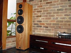
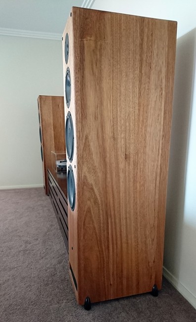
The speakers which this story is about are 1.45m tall floor-standers made of 31mm panels of solid Pacific Maple which give a lovely gold/tan/red colour in the grain. The back panel and bottom panel were made of a sandwich of ply and MDF because I had to cut costs somewhere. Wood is expensive.
The basic details of the speakers are below for those who are interested:
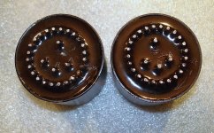
• Tweeter: Scan-speak D2905/9900
• Mid = Eton 7-360/37
• Woofers = 2 x Scan-speak 25W/8565-01
• Net internal volume of 133 litres with rear firing port tuned to 22Hz
I won’t go into the crossover details here because there were seven revisions since the original crossover design… I like to tinker.
It had third order filters with some impedance equalisation, mid smoothing and tweeter attenuation.
I was younger back then and I make no apologies for loving bass that went boom. Yes, I know it was wrong: I measured a 6dB peak around 50Hz – 60Hz, but I left it and I loved it! I listened to a lot more dance music back then.
31757916944_f924068c55_m.jpg

Anyway, I finished building the speakers in 2008 when I was living in the Crows Nest area of Sydney. Crows Nest is surrounded by water inlets, dripping forests, is reasonably close to the beach, is at sea level, and not least of all quite close to that big harbour of Sydney. All those points add up to humidity levels between 50% and 95% every day – hot or cold. Which is fine because the wood I used was purchased from a supplier in the local area. The speakers lived quite happily in Crows Nest for seven years without any sign of wear or damage. It seemed like they would be upsetting neighbours for decades to come.

This time last year, some big changes happened in our lives and we had to move to Canberra. Canberra is an inland town, surrounded by cleared farmland, is at altitude, and has no natural waterways. There is no humidity to speak of whether it’s hot, cold or even raining. Canberra, although being a lovely town, is practically a desert.

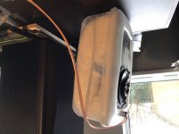
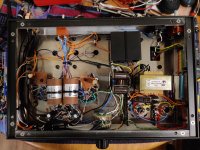
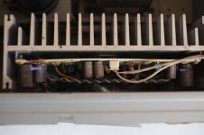
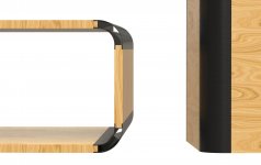
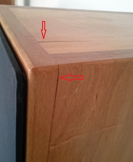
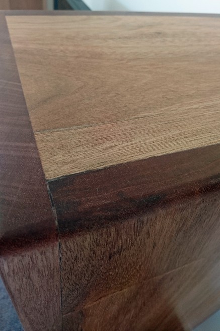
After about three months of living in Canberra I noticed some cracks appearing in a few of the joints of the speakers. A month later the cracks had broadened and a few more had appeared in other joints. Almost all the panels had cracked in some way except for the ply/MDF back panel.
32561094006_d3811cb183_b.jpg

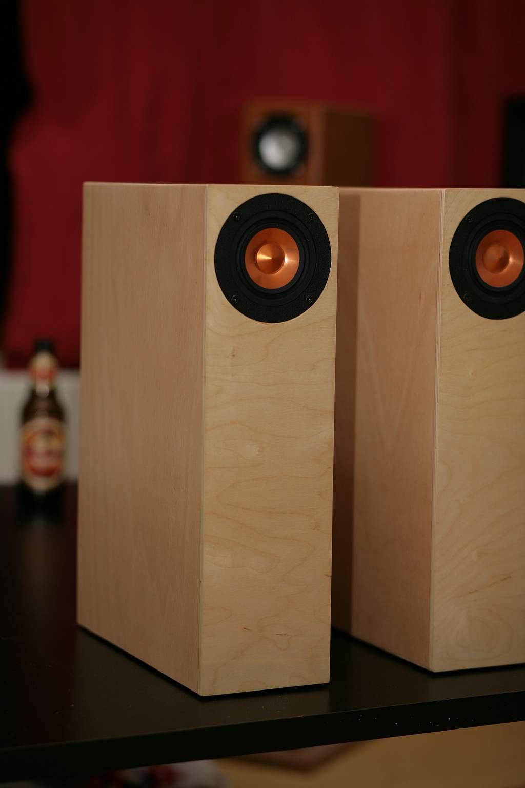
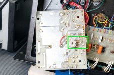
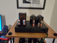
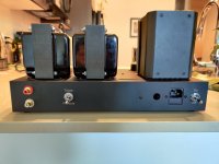
You can see in the picture the dark line where the front panel is pulling away from the sides. The top panel is also separating.

I found a local timber yard and furniture maker called Thor’s Hammer (great name!) which was recommended by friends who had bought furniture from them. I spoke to a bloke there named Gerry and told him about my situation. He said, “Yeah, that will happen. You should expect the moisture content to drop by about 12%, which means a lot of shrinkage.”
I asked if there was anything I could do to stop the moisture loss like sanding back and using oil to seal instead of varnish or something. The wood was expensive and I didn’t want to start again. Could I strengthen the joints?
“Nope. It’s going to shrink anyway. The joints are probably fine. The best you can do is leave it another couple of months to make sure the wood has reached the point where it’s as dry as it’s going to get, then sand back the varnish, fill the gaps with resin, sand back again, and use a flexible natural finish like oil.”

I had some time while I waited for the speaker cabinets to find their natural Canberra level of moisture and I figured if I was going to have to pull the speakers down, then I may as well tinker some more. I always thought the speakers sounded good (in all their versions), but the bass really was boomy with too much excursion. I’m older and …well … just older now and don’t appreciate the boom quite as much. I fired up Soundeasy and got designing. After a couple of months of designing and comparing options, I decided since the cabinets were already huge I could quite easily turn them into a transmission line.

I replaced the ply/MDF back panels with solid Pacific Maple like the rest of the cabinet. Sourced locally in Canberra. I took some more advice from Thor’s Hammer and left the lengths of wood inside to season for a month before joining lengths and cutting them into panels. This was also to find their moisture equilibrium.

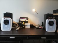
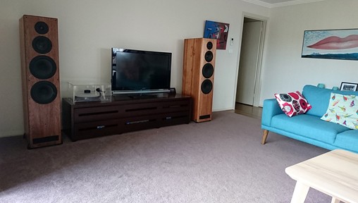
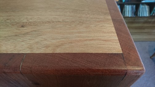
Four months of repairing, woodworking, construction and a lot of sanding later, I have functioning speakers again. I used oil instead of varnish, which made the wood grain in the cabinets a little darker, but nicer looking. I finished a few months ago, but I let them settle in before I wrote this just to make sure there wasn’t going to be any more movement. So far, all good.
32561093956_07e7c7ae3e_b.jpg

The only issue I have with the gaps now is my own mistakes I made with the resin. Otherwise it’s smooth to the touch (I ran my hand along many times), and they have a bit of a reclaimed timber look about it. From one metre away you can’t tell that there were ever any gaps.
31757917084_7c544ca422_b.jpg

31789502633_992d7c4ca4_b.jpg

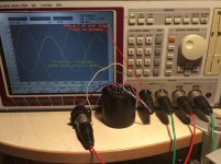
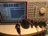
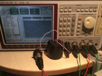
As for the sound, this was my first attempt at a transmission line and it lead to a lot of tinkering… I was in heaven! I had my measurement mic out every weekend for months! I had some phase issues which resulted in a slightly unorthodox fourth order filter for the woofers and third order for the mid and tweeter which did the trick. I did a lot of experimenting and ended up with lots of heavy stuffing in the transmission line which seemed to have only a little effect on the bass extension, but did tighten it up nicely. I now understand what people mean when they say their transmission line has tight and clean bass. It really is something different to the ported and sealed enclosures I’ve built. It goes deeper without lots of cone excursion and kickdrums have a nice clean “thump” without the boom. That’s all the subjective remarks I’ll make.
31789502573_6ff0819abf_b.jpg


I am very happy with the results. So, this is a precautionary tale but like all good stories, the main character learns a thing or two along the way and it has a happy ending.

In conclusion, if you choose to build with solid wood:
• Solid wood behaves like a live material – it expands and contracts with moisture levels.
• If you build with solid wood be aware that moving to a different climate may cause your panels to split or buckle.
• Source your wood locally and season it. If possible leave it inside your house for a month or two before you build.
• Don’t be scared off. There are ways to repair the damage from split wood, but not ways to stop it.

I’m sorry this ended up so long. I started typing and it just went on.
I hope this has been helpful to anyone who considers using solid wood. I intend to continue using solid wood.

AJ

31789502623_13d82d1bc9_b.jpg
  • Like
Reactions: metaphile

question on high-impedance line outputs when device powered off

Hi

I'm seeking some advice and any help would be much appreciated.

I have built a simple DAC that I am very happy with. The sound quality is excellent. There is just one thing that could be improved.

It has single-ended outputs that output about 3.2V peak to peak. These are directly coupled from the output stage, which is a differential amplifier (the INA2137) via a 33ohm series resistor (to somewhat protect against accidental shorting of outputs).

My issue arises when I have the DAC plugged into a mixing desk (an older Mackie model). It works fine until I power down the DAC, and then those channels start to pick up a lot of mains hum.

The simple fix is of course to turn down the volume on those channels, but I wonder if this could be fixed by adding a pull-down resistor to my outputs. It's only a short cable run of a few feet, but with no power my DAC outputs are high impedance / floating and that's enough to cause mains coupling into those lines.

I guess it's more common practice to add pull-down resistors on device inputs, but I don't want to mess with the Mackie.

I'm wondering what's typically done in this situation with pre-amps, DACs and the like. If pull-down resistors are added, it would solve this problem, but could affect the efficacy of the output stage, which would now see a lower output impedance when in use than it otherwise would. And I guess, more importantly, the desk, or other gear I plug the DAC into would see a higher input impedance.

I could:
1. Do nothing, and mitigate the hum by leaving the DAC powered on or only open those channels on my mixing desk when I'm using them.
2. Add a pull-down resistor. In which case, what value suits this application, and would I also add a capacitor in-line so I'm only pulling down A/C?
3. Something else I haven't thought about.

Thanks in advance for any suggestions.

Craig

  • Locked
Vintage vs New Amplification

Can vintage receivers and amplifier sound like new amplifiers? Lets discuss 1974 to 1980 vintage vs new amplifiers. New and vintage are of same design. There is no new technology. Both amplify a signal the same. Both use transistors, capacitors and resistors. Both have an AC to DC power supply. What are the differences? Plenty in the components. What is the difference in components?

First, the rectifiers are very quiet today in the power supply. The power supply is paramount to good sound. All an amplifier is, is a modulated power supply. Most new amps use Hexfred and some may use SIC rectifiers. Old receivers have noisy rectifiers and were not closed matched either adding to the noise. New amplifiers use better filtering vs old amplifiers or receivers.

The old capacitors in the audio coupling circuits (circuits that amlify the music) were of ordinary design and never produced to accurately pass audio. In older tube amps, they were quite good in many cases of passing good audio. Tube capacitors are low value film type capacitors thus better materials were used. Solid-state uses high capacitance electrolytic capacitors and these were not made to pass quality audio. They were the same as a power supply capacitor that has a different function. New amplifiers use what is called audio grade electrolytic capacitors and they greatly outperform the old capacitors.

The transistors are somewhat the same in late 1960s and '70s amplifiers. Old transistors were low noise audio transistors, but low noise at the time period. Newer transistors operate more quiet. But, the level of low noise does not make a large difference in the sound. Phono sections are the largest benefactors of quiet transistors. But, for the most partsnew transistors do not necessary sound better (some may disagree with me). The are exceptions such as First Watt amplifiers. But, you are getting into an area you may need $5K speakers to clearly hear the difference. First Watt has many models and the transistors are tuned for a certain sonic signature. If you can afford a $4K+ amplifier, you may have no interest in a vintage amplifier or receiver.

Resistors have not changed much. Older vintage used for the most part carbon resistors and newer amps use metal film. There are boutique resistors today vs none years ago. They may make a difference, but frankly not a lot. Most new amplifiers use standard metal film, not boutique resistors. In some cases new amplifiers may use carbon film for the more lush sound. Not a bad decision. Old potentiometers may require a DeQxit cleaning. I have always had good success on 'scratchy' pots, but you may need a new replacement. Most 1974-1980 used a separate power switch, thus new manufacture is readily available. If an odd resistance is encountered, replace with next higher resistance pot and bridge the potentiometer with a 1/2 watt resistor to achieve original resistance.

So, what happens to a quality designed vintage receiver or amplifier using the better new components and an upgraded power supply? A lot! First, the small soundstage becomes huge. Better clarity and lower distortion. This includes higher order distortion that also effects the quality of sound. The power supply can use 2 to 2.5 times the original capacitance for better filtering. The new capacitors are much smaller than old capacitors thus fit well in the higher capacitance values.

Old receivers and amplifiers may use an op-amp in the phono section and at times in the pre-amp. These old op-amps were not designed for quality audio like the new op-amps. And, some prefer discrete new design vs any op-amp.

Some think when you upgrade an vintage amplifier or receiver, you will still get the old sound. They also do not think the superior parts adds to the sound quality. These same audiophiles are not technical in the least.

I say you replaced the poor performing parts, what's left? Transistors? Older carbon resistors? The transistors do not make a huge difference. Both old and new are made out of the same silicon. Old carbon resistors are still used today. Basically carbon is carbon, nothing complicated about that!

An upgraded vintage amp and receiver will sound very different and very good. Rebuilders on ebay used audio grade capacitors. They may need to be prompt to double the power supply capacitor capacitance and to use Hexfred or SIC rectifiers, but they will and can upgrade your vintage receiver for a base cost around $400. They will check for out of tolerance resistors too. They also know what resistors to look for due to their experience.

I used to say no way to solid-state as I am a tube amp audiophile. I rebuild an Allied 395 (same as Pioneer SX-1000TW) and was shocked how good this receiver sounded. It is close in performance to my best tube amp and I used Revel M22 speakers that are reported to outperform KEF LS50. Not a shabby speaker to hear quality sound despite what one audiophile said. I have not directly compared my Allied 395 to a new Rega Brio or Cambridge CXA81 amplifier, but I think my Allied 395 would compare. Would my Allied 395 compare to a First Watt amp? No way, but it still sounds good.

Three non op-amp vintage receivers are: any Pioneer in the SX-800 (not SX-890) and higher number such as SX-1010, etc. Any Marantz 22xx series. And, the low cost sleeper? Onkyo TX-2500 MKII (40 watt per channel) & TX-4500 (60 watts per channel).

Your thoughts?

Model for current output DAC in Spice

Hi

My first post in this part of the site.

I am just starting to use Spice to model analogue circuits for the audio out from DACs. Several DACs provide their output as a current swing. As an example, the classic TDA1541 sits at a -2mA current sink with no signal and then swings ±2ma for full level.

I know that a current source with both AC and DC characteristics is available in Spice but the actual behaviour of a 1541 o/p is going to be more complex than that e.g. a finite output impedance. I thought about modelling this as a resistor in parallel with the current source?

Also, what is connected to the other end of the current source? My two current thoughts are either ground or the -6V supply.

TIA

Michael

Multiway SEAS Speaker design questions

I’m looking at building a new HIFI and at present are in the process of selecting components.

The system will be a DAC with DSP -> AMP -> 2 way speakers bi-amped with active crossover. I have the scope to add a sub later if I feel it’s needed. I also have the gear and understanding to take measurements & implement for active crossover.

Based on my research my current thinking is;
1. DAC - miniSHarc DSP + Buffalo III DAC
2. Speakers – SEAS W18NX001 + T25CF001 (there are a few plans around based on these so I can easily change cabinets if desired).
3. AMP - HYPEX 4 x UcD180HG with HxR


My Questions;

1) HYPEX Modules – The UcD180HG with HxR will be sufficient to power the proposed speakers, but I’m wondering whether it’s worth considering upgrading 2 of the modules to the UcD400HG w/HxR for the W18NX001 drivers for additional headroom (n.b. The W18NX001 is rate at 90W RMS continuous into 8Ohms). Therefore UcD180HG for the highs UcD400HG for mid lows. Is this just overkill?

2) For the tweeter, a potential upgrade would be T29CF002 but is a massive step up in price vs. the T25CF001. I am considering the T29CF001 as a substitute but is still double the cost of the T25CF001. Would it be worth it? What can I expect?

3) Speaker Porting – If I was building a Sub I’d definitely go closed box for the benefits of a flatter response (understanding impact on power requirements). Can the same be done for Mains (i.e. sealed box)? I don’t see a lot of un-ported designs so am wondering if there’s a reason why other than efficiency? I’m thinking of trying say the SEAS Bifrost or Troels CNO-T25 designs but un-ported.

Any thoughts and experience with the above appreciated.

Thanks in advance

Siliconix data booklet 1986

I needed a U1899 fet to repair and old instrument. In my search for data I found this data booklet. So here it is, in case it may be of use for others:

http://bitsavers.informatik.uni-stuttgart.de/components/siliconix/_dataBooks/1986_Siliconix_FET_Databook.pdf

It is too large for upload. Should the one at the link disappear I have a copy.

(This part of the diyaudio site seems to "self-oscillate" the most about old parts. One of the admins might move it to a better location - thanks).
Projects by fanatics, for fanatics
Get answers and advice for everyone wanting to learn the art of audio.
Join the Community
507,772
Members
7,887,858
Messages

Filter

Forum Statistics

Threads
406,201
Messages
7,887,858
Members
507,772
Latest member
Hypertone