National Matsushita 7dj8-Pcc88 Matched pair

For sale matched pair of superb sounding tubes that you can use in place of Ecc88 or 6dj8.I buy this about two years ago from upscale audio when they become this in stock. This tubes are new and Nos! I Pay for this pair 100usd+30usd shipping+25usd taxes in europe.Tubes are verry low nois and microphony-platinum grade! I would sell this for 60 euro plus caa. 7,90euro shipping inside EU. Payment plese with paypal!

Attachments

  • IMG_20210522_182517.jpg
    IMG_20210522_182517.jpg
    505.4 KB · Views: 183
  • IMG_20210522_182523.jpg
    IMG_20210522_182523.jpg
    499.7 KB · Views: 175
  • IMG_20210522_182538.jpg
    IMG_20210522_182538.jpg
    479 KB · Views: 168

A constant-Ic β-tester: β-Master 🌈

This tester was developed as a spinoff from this thread:
https://www.diyaudio.com/forums/sol...collector-current-hfe-tester-transistors.html

The circuit proposed proved too complex for the OP, but I decided to bring it to completion anyway: it is probably a useful piece of kit for many DIYers.

The complexity, especially in its finished form, might look daunting, but that's kind of inevitable with this type of instrument: many parameters need to be made variable, and being a transistor tester, it has to accommodate both sexes, which brings another layer of complexity.

That said, the complexity is relative, and no expensive component is required.

It can be built as a naked board, with an external supply and multimeters as indicators, or as a complete, self-contained instrument (or anything in-between).

It does have some attractive features: it covers most of the needs for DIY use, with an Ic range of ~150µA to 1.5A, a Vce of 0 to 10V, requires a single unipolar supply, and the switches for the range and polarity are ordinary DPDT types (one has a center OFF).

A constant Ic tester is very convenient compared to alternatives improvised with supplies for example: comparisons are immediate and straightforward.
The direct-reading is also very convenient.

I didn't build and test a complete instrument: I just breadboarded the functional core for NPN (which operated as expected), and I also tested critical sections, like the polarity handling meaning the project is relatively safe.

The complete instrument has been tested in sim, and is functional (I include the .asc).
Note that this is a DIY-grade instrument, not a lab reference, but with care in construction and a good calibration, it is OK for a +/-1% accuracy, which is ample for a parameter like β.
Comparisons can be made with a greater accuracy.

This is the circuit:

attachment.php


And a sim showing the measured value against the actual value (β+1 because what is actually measured is the ratio of Ie to Ib, not Ic/Ib):

attachment.php

Attachments

  • Betamaster0.png
    Betamaster0.png
    67.6 KB · Views: 1,059
  • Betamaster1.png
    Betamaster1.png
    48.1 KB · Views: 1,079
  • Betamg.asc
    Betamg.asc
    34.3 KB · Views: 97

HYPEX Ncore NC252 Amplifier : free shipment to Europe

Hi,

I sell my Hypex Ncore NC252 brand new.
Made with great components and with AC Audio Grade filter.

420 euros shipped to Europe Only


The NC252MP has been reviewed here :

Review and Measurements of IOM NCore Pro PWR Amp | Audio Science Review (ASR) Forum

2x150W / 8R
Low THD
Nice amplifier for all day use

- NC252MP
- Full All Case
- Audio Grade AC filter
- Sommer Cables Germany
- Push Banana Plug
- Full balanced XLR inputs


New to DIY amplifier building

I must confess that I'm very new to DIY amplifier building. I'm more familiar with speaker building though.

I'm interested to build a Class-D amplifier. Yet, I don't know how to start it.

I'd like to ask guru in this forum that is there any cookbook about Class-D amplifier building available, as the speaker building has such as Vance Dickason's?

I've already googled it. But, only I found was apart from Class-D, mostly Class-A and AB.

Neurochrome 686 Brand New Build

I was intrigued by reports of how good these Neurochrome modules are and also had a few requests to build some, so I thought it was time to try some out and evaluate the amps. The build was fairly straightforward and I used a chassis from Modushop who supply most of my cases. Tom the designer provides drawings for this chassis and suggests the large chassis shown in the accompanying photo.

The amp has a slow start module, and includes a sophisticated output protection system to protect your speakers. In practice, it turns on and off without a thump or buzz, with a small click as the relay clicks over. Construction is fully dual mono, and fully balanced with inputs by XLR. I’ve fed the amp with single ended source from my own brand ESS9038pro valve DAC, and also used a fully balanced source too. There's no great difference in sound quality between the two.

Residual background noise is effectively inaudible, even with my 96db sensitive JBLs, and sensitivity standard at 2v.

I’ve run the amp now for some 24 hours so it’s partially run in. Overall, I’m very impressed. I should confess here I’m a valve man through and through, with 845, 805 and KT120 monoblocks in the house and studio. But I do get quite a lot of high end
Solid state gear through my workshop and also tried the Nord Class D amps a couple of years’ ago and have built Hypex-based amps for clients, but both of the latter left me cold.

This amp on the other hand is very musical. It’s neutral and revealing, but without robbing music of its soul. Bass is powerful and tuneful, and soundstage wide and deep. Higher frequencies are convincing, unlike IMO Class D amps that I’ve heard. For anyone who has an aversion to valves, young children or mischievous pets, or in need of 200 watts into 8 ohms, 360 into 4ohms, this could be the amp for you. I would rate it above the large Krell or Mark Levinson amps if you want a comparison. Tom the designer makes a lot of the need for a lot of heatsinking but with my 90db and 96db sensitive speakers the heatsinks hardly rise above room temperature.

£2,650

RCA switch grounding

I am planning on making a switch box with 1 RCA in and 2 RCA out. The purpose is to connect one preamp to 2 power amps. I can buy one like in the photo but would rather build it and I already have all of the parts.

Question:
Should I only switch the + signal and just connect all of the grounds together or switch both the + signal and grounds for each? Or wire it differently?

This is what I am talking about:
attachment.php


Thanks

Attachments

  • RCA switch.jpeg
    RCA switch.jpeg
    30 KB · Views: 1,212

Dual 701 and tonearm mods

It took me some time to get the courage to work on my Dual 701.I did some work on the electronic section replacing the capacitors and the discrete series regulator with a MC7815CT which also trips at 800mA so current protection is now included, just in case.... for those rare germanium transistors.
But what really drained me was to rework with copper and lead its tonearm counterweight cause i broke the original one out of curiosity just to see what dual resonant counterweight means...and it led me to the actual counterweight system which is develloped more on the horisontal being also heavier and closer to the pivot allowing both fixed and fine tuning weights to be damped.I actually cut by 2/3rd the internal brass rod attaching te counterweight to the toneram to make the tonearm itself as light as posible.More work on that later as i don't really like heavy tonearms and preffer to get the damping trough different methods .I also added my new semiautomatic 12 inch tonearm that has also end of record electric sensor and lift and conceived a leaf spring based system additional to its own spring damping system.Thus i removed the 701 original wooden enclosure and kept the internal platic support cut to a minimum and adding some more silicon rubber damping basically creating two completely separate damping systems that can also accomodate my other Dual 1219 turntable as 1219 and 701 need identical spring fixture .More work and photos later this year.

Attachments

  • IMG_5510.jpg
    IMG_5510.jpg
    835 KB · Views: 1,036
  • IMG_5511.jpg
    IMG_5511.jpg
    819.1 KB · Views: 866
  • IMG_5515.jpg
    IMG_5515.jpg
    866.8 KB · Views: 692
  • IMG_5516.jpg
    IMG_5516.jpg
    865.4 KB · Views: 690
  • IMG_5485.jpg
    IMG_5485.jpg
    976 KB · Views: 768
  • IMG_5490.jpg
    IMG_5490.jpg
    787 KB · Views: 653
  • IMG_5492.jpg
    IMG_5492.jpg
    900.4 KB · Views: 646
  • IMG_5496.jpg
    IMG_5496.jpg
    900.9 KB · Views: 615
  • IMG_5499.jpg
    IMG_5499.jpg
    957.3 KB · Views: 584
  • IMG_5502.jpg
    IMG_5502.jpg
    891.7 KB · Views: 631

Advice on a kit?

Hello One and All,

I’m N3rd and this is my first post.

First let me say that I’m blown away by some of the amazing projects being shown here, I wish I had half as much talent!

Like everyone, I like as much bang for my buck as I can get. And, as I’m sure you’re all aware, excellent HiFi can cost a lot.

So, I’ve gotten it into my head that the most economical way to get great speakers is to buy a kit.

However, the problem with kits is that there are far fewer reviews to help sort the excellent from the good from the OK etc.

The kit I’m interested in is the Visaton MONITOR 890 MK III.
Link:
Visaton MONITOR 890 MK III - price per pair. – Impact Audio

Now, nearly £4000 on a kit is a lot of money, so may I ask if anyone has had any experience of how these speakers sound?

I know it’s a personal thing, but if anyone could give me some clue about how they sound, and if you heard better, what that was?

Quite a big ask, I know but info on kit quality seems a bit thin on the ground.

Thanks in advance to anyone taking the time to read and comment.

N3rd.

Looking for advice on reusing midwoofers and tweeter for active speaker

I wanted to learn more about DSPs and active speakers. So I got myself an ADAU1452 board and a 6 channels TPA3116 amplifier, as a starting point. And the DSP programming part is pretty well understood at this point

Instead of buying a few random speakers online, I found a Craigslist deal and got a couple of DIY tower speakers with one tweteer and 5 midwoofers. 12 individual speakers to play with for the cost of a cheap lunch for two.

The current speakers are in a 3/4" MDF box, 8"x15"x44", no bracing, and lots of fiberglass batting insulation inside (yuck, hate fiberglass). I listened to the speakers, and pretty much hated the sound (weirdly, almost no mids, and very hot high frequencies. Granted it was a quick test and the speakers were very poorly positioned). The design and build seems very competent, and there is a pretty beefy crossover, which seems well built; the midwoofer closer to the tweeter is in its own separate enclosure, also filled with fiberglass, so I can only assume that the builder actually wanted that sound signature. To each its own, I guess. Pretty sure that the boxes will be given away, too big for my rooms anyway and even if well built, would require too much work refinishing them for any type of WAF.

So now I find myself with 10 MCM 55-1870 midwoofers (specs enclosed) and two Dynavox 53-570 tweeters (no real specs, just a frequency range and sensitivity info). Very little information on both, especially the tweeter. From what I could find, those were semi-decently regarded cheap speakers, especially the midwoofers, and the tweeter is known to have higher sensitivity at higher frequencies, resulting in less-than-linear graph. But since I plan to use a DSP and dedicated amplifier for each channel, I can correct that.

Let me say upfront that I have no expectations to end up with a good speaker. My goal is to learn, and learn as cheaply as I can, reserving the budget for better components once I know enough

At the moment the speakers I listen to the most are a pair of Paul Carmody Speedsters I built from a kit. Love those speakers, and one day I will experiment more with ribbon tweeters

I was planning to build a 3-way active speaker, with a tweeter, a midwoofer in a standalone enclosure and 2 (or 4) midwoofers as bass, with a port to help reinforce the bass. It's unclear to me if crossing over the single midwoofer differently than the 2 or 4 "woofers" will help improve the sound vs using all 5 midwoofers with similar filters. That's part of what I want to see first hand and learn. I listen mostly at low volume, and relatively close by in smaller rooms. I'm not looking for a visceral bass (I also live in an apartment, and powerful bass tends to p*** off neighbors very quickly)

But given my listening habits, I was thinking also about an open baffle design (which, incidentally, it's easier with the limited tools I have in the apartment. I used to have a decent workshop, but not anymore). Clearly with the puny midwoofers I have, a true open baffle will have no bass, so maybe an open baffle for the tweeter and one midwoofer, and the other 2 or 4 woofers in an ported enclosure.

Any suggestions? What would you do with the random set of components I have? What is worth exploring, to learn more about active speakers? I don't have enough for a linear array, even if I saw a design using 8 of my same woofers Kevin's Straight 8 Speakers (but I have no intention to buy more of those)

I think I can tame the tweeter to sound close to what I like. But maybe I should consider a real woofer (no bigger than 6-8") to complement what I have. If so, suggestions for a cheap/honest woofer to consider are welcome

P.S. If anyone local to Seattle is interested in the boxes, send me a PM. The box is pretty well done and with a different baffle can be used for quite a lot of designs. I just don't have the space to store it for the future

Attachments

  • Tower speaker.jpg
    Tower speaker.jpg
    157.2 KB · Views: 160
  • 53-570 tweeter.PNG
    53-570 tweeter.PNG
    227.8 KB · Views: 157
  • MCM 55-1870.pdf
    MCM 55-1870.pdf
    2 MB · Views: 86

EAR834 small hum problem

Hi tube friends. I have question about how to tackle small hum problem in aer834 clone. Its ebay kit, works great, sounds sweet, but it has ~12 mV hum, looks like 60hz on output. I use 12 Vdc on heaters, well filtered. I use ~200 Vdc to power it, two sets of filters, each channel separate. When i touch the grouning connector, the one you use to ground the wire from turntable, hum is lower, but still there. I am only testing it with cheap sony ttable, no separate ground wire. Preamp is not in box, just on the floor. What should i try to eliminate hum?

Btw i built shure m-65 tube riaa preamp, ebay kit, and it works great, sounds great, no hiss, no hum, no box, just testing. No hum whatsoever.

Thank's for suggestions.

JLH "Liniac" RIAA

Hello everyone!

I intend to make a correction RIAA preamp transistor for a friend but I would like to have your opinion on the following diagram.
I also have a question about the capacitor 250uF is it related to the RIAA is correct or that a 220uF capacitor is suitable?
The link to the original scheme is on the website of Paul Kemble (A Paul Kemble web page - John Linsley Hood preamp designs.).

Thank you!

Attachments

  • Liniac.png
    Liniac.png
    7 KB · Views: 1,629
  • RIAA.png
    RIAA.png
    42.2 KB · Views: 1,605

Driving RGB LED's

Maybe not the right place here on an audio forum but in "Everything Else" we can post other things .
I've been looking for a way to drive RGB LED's so that with like up/down buttons I can fluently change the colours.
Looking at the IC's on Mouser or Texas Inst sites , I can't see the trees through the forest. So many LED driver IC's but not what I am looking for.

Closest I've come to designing it myself is an up/down counter that drives the addresses of an EPROM , and its output drives the PWM of the 3 LED colours.
Problem with this is progamming the EPROM.
Even with 5 bit resolution/LED , that's near 100.000 adresses of a 1Mbit EPROM ... by hand .
There must be an easier way but without an uP using only custom IC's with logic and EPROMs.
How does Philips Hue do it ? How would you do it ?

NC400 general input Q's

Hi -
(OK - covered elsewhere, but all a bit disparate/technical for novice - looking for summary of input Q's - therefore hope this is relevant/helpful to others)

I am driving NC 400 via balanced out from DAC.

1; NC400 passive pot wiring; was recommended as in fig A - have been running fine for some years - though would fig B be better?
(I did run S.E. for a while, and I think A is Hypex's recommendation for this...)

2; I'm considering the addition of an external buffer (n.b. have no long runs...) - some say; more dynamics, a bit more warmth, though I understand this is less if at all applicable to NC400 as it has built in input buffer stage. A simple 'KISS' ('keep it simple, stupid'!) or 'ACT' (active!) opinion without the trouble of huge technical explanation would be hugely appreciated.

I understand my Q's are painfully basic, thank you for perseverance!

Attachments

  • P1020651.jpg
    P1020651.jpg
    141 KB · Views: 162

Transformer orientation

Hi, I asked this question in another thread, but perhaps here is the right place to ask.
I just copy-paste it, hope this is ok.

"After a very long time on a MDF board my D3 will receive a case. I bought a Linn Intersekt case for very little money and now mod it to my needs.
My question is : Which way to mount the PSUs would you prefer and why ? Is there a difference if the transformers are side by side, facing away from each other or even one on the floor one on the wall ? Which would make sense ? Here are my possibilities."

Perhaps i should have asked in the PSUs section first.

Attachments

  • LINN01.jpg
    LINN01.jpg
    563.2 KB · Views: 161
  • LINNPSUs.jpg
    LINNPSUs.jpg
    775.8 KB · Views: 162

Improving the hollow plastic phase plug in Seas driver

I've just bought a pair of Seas CA18RNX/P drivers, and the phase plugs are a hollow moulded plastic item. They sound hollow when tapped and fall off when twisted. So now curiosity has got the better of them, I could fill the hollow with resin or silicone etc to fill and dampen them. Or go full nut job and machine a new pair of plugs from aluminium or copper and fit them with a bolt through the 'pole vent'.

What would be the better option? Is there an issue with copper or aluminium above the gap only, forming an eddy current shorting ring for the positive stroke only?

OR should I just fill them with 2 part silicone to deaden them and stick them back in with some epoxy?

thanks

Tango FX-40-5 Output Transformers (Pair) 5k

These are used but in superb condition. Ideal for 45, 2a3 or 300b push-pull. For inspiration check here: "Fatboy" 300B Push-Pull Amp

I am looking for 450 swiss francs for the pair plus shipping.

Shipping to Europe and UK is 50 swiss franks
Shipping to USA is 75 swiss francs
Shipping to Japan and Australia is 90 swiss francs

These are original Hirata Tango transformers. Secondary connection for 4, 8 and 16 ohm.

I really hate to part with them, but need to reduce. PM me if you have interest. I will post photos soon.

Ian

Lii Audio W-15 in an aperiodic enclosure?

Given the big Lii Audio driver is of a high Qtc of 0.79...and has a 8+mm of Xmax...and a very uncontrolled Qms value...The driver sims as wanting to be sealed, has a mid-twenties F3...the enclosure size is rather impractical....has anyone tried an aperiodic enclosure?
No, my cheap open-baffle days are long gone, and I "don't believe" the hype of baffle-less proponents.
The actual mathematical science of Aperiodics has not been put to paper & calculator as of yet.
Thoughts?


-------------------------------------------------------------------------Rick....

Designs similar to the BD-Pipe

Back in the mid-Naughties, I had 4 of the Radio Shack 40-1197 drivers, and spent many a happy hour checking out speakers that used them. The BD-Pipe always appealed to me. Folded pipe, with a 45-degree rear facing driver for added spatial neat-o-ness. But I never built anything.

So, now, a decade, a divorce, and a lot of livin' later, I am once again seated in front of a computer, looking at small full-range speaker designs. And I still like the ideas in the BD-Pipe design.

So, are there current designs that are similar? 4" - 4.5" FR drivers, compact tower, easy build, easy load for low-powered amplification, and with that angled, (or upward-facing,) psuedo-omni driver. Corner placement is a must in my tiny, weirdly shaped living room. and it's an upstairs apartment in an old house, so lotsa bass isn't a goal.

--Shannon

Parts in Mumbai (India)

I had this strange experience. I was looking for polypropylene capacitor in Lamington
Road Mumbai. I got a reference from one shop that Apex electronics in one of the lane
has such capacitors. Apex said it can be made only in bulk order and it is not
available usually as these are very expensive capacitors. So I looked for some more time
and then gave up being too tired of hopping around shops on that road. Finally looked for
in the internet and ordered from Futurlec. It took about a month and I got the caps. Happy!
Only day before yesterday I searched the net with the cap number (AC-X2) which I got
from Futurlec and surprised to find that these were available in Visha Electronics. I went
to Visha at least twice before, they always said they DO NOT have polypropylene caps.
They do not even know what they have. Then yesterday the moment I said AC-X2 they
said yes yes we have.

What do we do????

So my request to all fellow DIYers from India/Mumbai that we maintain this thread for
this purpose of posting names/addresses of shops where we can find certain parts.
Or for any such strange stories.

I start:

AC-X2 (polypropylene) capacitors (less than or equal to 1uF): Visha electronics, Lamington Road.
They take online order also. Online Shopping in Mumbai

Regards
Roushon.

Cinemag 1254 SUT Round II

There have been several requests to do another Cinemag 1254 step up transformer group buy. Delivery time will likely be 8 weeks from date of placing the order. Price for the standard configuration would be $190 per pair. The center threaded bushing would be $200 per pair. Only one type per order, minimum 10, so we need to decide on the most desired configuration.

Price breakdown is as follows:

The price for standard mount will be:
CM-1254 pair $190.00
CA Sales Tax 9.5% $ 18.05
Pro rated shipping from Cinemag $ 5.00
Priority Mail Insured (U.S.)* $ 10.75
Total $223.80

The price for center threaded bushing mount will be:
CM-1254 pair $200.00
CA Sales Tax 9.5% $ 19.00
Pro rated shipping from Cinemag $ 5.00
Priority Mail Insured (U.S.)* $ 10.75
Total $234.75

* International Priority Mail Small Flat Rate Box will be quoted individually, but expect $27-$40 USD

Payment to confirm your order should be made immediately after the GB is officially closed. This will allow me to commit to the exact number of transformers and confirm production scheduling with Cinemag. I would look to the GB being closed on August 31, to get the order in before the U.S. Labor Day holiday.

Cheers,
Geary

Attachments

Urgent help needed with NE5532 OPAMPS

Hi all,

At the end of doing my final project for university (making guitar pedals), and have run into a wierd issue. One of the pedals utilises a spring reverb tank to acquire its effect, so i've been following a schematic found online that uses NE5532 opamps to drive, recover and mix the circuit. However, whenever they are plugged into the +15v and -15v power supply, as required, they turn on and off again repeatedly. I absolutely cannot figure out why this is! Any sort of help would be massively appreciated.

See links for the circuits:

https://sound-au.com/articles/rvb-f5a.gif

https://sound-au.com/articles/rvb-f9.gif

https://sound-au.com/articles/rvb-f12.gif

F/S Mil Spec 2 Cond 12 & 10 Awg Silver Plated Wire

I just bought a good quantity of some Mil Spec 2 Conductor 12 & 10 Awg Wire
Mil Spec M22759/44 Silver Plated Copper Wire. Have 12 & 10 Awg Silver Plated Copper Braided Shield and one 10 Awg 2 conductor Unshielded.
Great for Speaker Wire, Car Amplifier wiring, and vacuum Tube Audio

Here are the part numbers

M27500A 12SR2M23 - 12 Awg 2 conductor Shielded $4.00ft
M27500A 10SP2M23 - 10 Awg 2 conductor Shielded $4.50ft
M27500A 10SP2U23 - 10 Awg 2 Conductor Non Shielded $4.00ft

Now in Stock
not yet listed on my website

Attachments

  • DSC01386.jpg
    DSC01386.jpg
    985.1 KB · Views: 283
  • DSC01387.jpg
    DSC01387.jpg
    507.7 KB · Views: 276

Marshall Valvestate vs230r repair tips?

A friend of mine has a valvestate amp that has let out the magic smoke. He said he was in the middel of playing Smoke on the water, so he was clearly asking for it. 🙂
It is this specific model : https://schematicheaven.net/marshallamps/vs230r_2x30w_stereochorusrev.pdf
R18 has clearly burnt, everything else looks Oke. Can anyone shed some light on the possible cause? I’ve measured sec. on the transformer which seems to be oke at 17,5 volt.
Also ordered 2 new TDA2050 as they are dirt-cheap. But before I replace them, what should I check?

Infinity Kappa K4 distortion

This is a 4 channel class-d amp. The output is highly distorted. It had this issue brand new out of the box. This is my first attempt at repairing an amp. I have been trying to troubleshoot the issue by following Perry's tutorial, which is amazing, but it is a lot of information to digest and I am stuck.

The output is highly distorted at all gain levels, but gets worse as the gain is increased. None of the other switches or knobs have any effect on the distortion. The distortion is the same through both the RCA inputs and audio played through the amp's BT connection. All 4 channels are distorted. When just one (any) RCA input is connected, the audio is present on all 4 channels and all are distorted. The output is a little louder on the connected channel, but is easily heard on all channels.

I have checked the power supply rails at the rectifiers and I see clean rails of approx +40v and -40v on my scope.

I checked for oscillation on the output FETs and I see a square wave that peaks at approx +40v to -40v.

I don't really know where to go from here and could use some direction. Thanks in advance.

Threshold amplifier help, please!

Good morning, all,

I'm hoping that Nelson Pass or another expert here might be able to give me any advice on any electronic components I might be able to test (and replace) myself as I have a hissing sound coming from the right channel of my T800. When I power down the amplifier, I also get a fairly long hiss with high-pitched sounds mixed in, only on the right channel.

It wasn't likely that this was going to be any of the top fuses but I did verify that those fuses are all OK.

Any help much appreciated!

Best,
Ross

Boring question: What's the common order of input-/output-connections

Good evening
After my 3rd or so back-plate (attempts included), I'm still not sure if there's a common order of what goes where (and why).

Functionally, as long as stuff is done reasonably, I guess it doesn't really matter if the IEC is on the right or left side. But then, should things have a certain order,

  • for technical reasons?
  • Just because it's quasi standard?
  • or is it lastly just sheer aesthetic reasons and maybe a brand's ID?

probably a bit of all, but the technical and "historic" reasons are those I'm most curious about ...

JBL's take on the Unity Horn

There's a bunch of threads on here regarding the Unity horn; it's basically a three-way D'Appolito array, folded around a conical horn, with a coupling chamber inserted to reduce harmonic distortion.

Multiple_entry_horn.png


Geddes pioneered the use of reticulated foam in waveguides. In a horn or waveguide, a significant percentage of the radiated sound is delayed in time. This is because a percentage of the sound is reflected off the mouth, and a percentage of the sound does not travel down the center of the horn or waveguide. Those waves are absorbed more than axial waves, as they travel further.

An externally hosted image should be here but it was not working when we last tested it.

Geddes and Duke LeJeune, from about six years back

Looks like JBL was listening - they've created a loudspeaker which combines a bit from both.

An externally hosted image should be here but it was not working when we last tested it.

An externally hosted image should be here but it was not working when we last tested it.

JBL_VT4886LeftGrill-large.jpg


In the three loudspeakers above, the tweeter is at the apex of the horn, just as in a Unity horn. And the midranges flank the tweeter, as in a D'Appolito. But there's a coupling chamber in front of the midrange(s) - just like a Unity. The reticulated foam is used here to good effect, particularly in the line array. Here's quote from the patent:

"The RBI is a substantially solid boundary that is placed over the mid-range speakers to provide smooth, wave-guiding side walls to control the angular radiation of the high-frequency sound waves emanating from the high-frequency sound sources. To allow the mid-range frequency sound waves generated from mid-range sound sources to pass through the RBI, the RBI is designed with openings. To further prevent the possibility of having high-frequency sound radiate through the openings in the RBI, the RBI may be designed with porous material in the openings of the RBI. The porous material would be transparent to the mid-range sound radiation, but would prevent the high-frequency sound radiation from being disturbed by the openings in the RBI."

An externally hosted image should be here but it was not working when we last tested it.

An externally hosted image should be here but it was not working when we last tested it.

The graphs show performance with and without the RBI device. (the coupling chamber, like a unity horn.) The difference looks subtle, but keep in mind each segment is TEN dB. Note how the off-axis response is improved, particularly near the crossover point. This is right in the important vocal range, where six dB dips are surely audible!

If anyone would like to learn more, take a look at patent 7134523

Tube subwoofer amp

Hi all,

Well after getting my 6V6 PP stereo amp sounding real nice, (check my other threads) I am looking for a new project.

I have a 10"sub in a box sitting around, and access to a variety of big *** tubes (some smaller transmitting triodes and stuff) which I can get for free. I am wondering about using a single-ended triode amp with negative feedback, using one of these tubes. My question is: what kind of power/output transformers would I need?

I was thinking I would need a reasonable power tranny, however the amp would probably only have 2 tubes: an octal triode like the 6SN7 as a preamp (heck, maybe even a 6V6 as a preamp!) and a big coke bottle power tube. So maybe I could get away with a scrounged tranny from a big console radio... Maybe?

I am thinking around 30W RMS would be good enough for a fair bit of bass, could I use a toroidal power transformer as an opt? I only need a freq range of 20-120 Hz, and I am using NFB, so would that be good enough?

Any other crazy person thought about this (or done it 😀)

~~H~~

Measuring T&S parameters using current drive

Something that just popped into my head and I haven’t really thought it through yet... what if you measured a driver's Thiele and Small parameters using very high impedance current drive instead of the usual low impedance voltage drive? For one thing, the Qes would measure a great deal higher. Given that the measured parameters would be different, you then go about constructing a bass reflex box according to these new parameters and feed the driver with a current source amplifier. I wonder what sort of results you would get? For one thing, the cone displacement would likely shrink right down at the box/port resonant frequency, more than usual.

This question is not simply about the usual ins and outs of feeding a driver with a current source signal. That has been done to death. This is about feeding a driver with a current source signal while it is in a bass reflex box that has been calculated from a driver that has had its parameters measured using a current source signal.

Edit-> I just realised that the resistor you put in series with the speaker to do the measurements in the normal fashion turns the signal into more or less a current drive anyway. Told you I hadn’t thought it through...

ASTRODYNE Finned Heat sinks 1 TO-3 Transistor Amplifier Amp Power Supply heatsinks

I don't know if they are all ASTRODYNE / IERC heatsinks.
Some have no writing on them.

$20 a piece or best offer for the large ones
$10 a piece of best offer for the small one
Selling in the lots you see in the pics.
Shipping is included and via USPS medium flat rate box.

Dimensions are in mm.
Quantity is written on them too, most are circled.

Attachments

  • 20210525_122022.jpg
    20210525_122022.jpg
    992.5 KB · Views: 170
  • 20210525_122028.jpg
    20210525_122028.jpg
    1,002.5 KB · Views: 153
  • 20210525_124339.jpg
    20210525_124339.jpg
    1 MB · Views: 155
  • 20210525_124348.jpg
    20210525_124348.jpg
    980.2 KB · Views: 164
  • 20210525_124354.jpg
    20210525_124354.jpg
    899.1 KB · Views: 148
  • 20210525_124410.jpg
    20210525_124410.jpg
    1 MB · Views: 71
  • 20210525_124914.jpg
    20210525_124914.jpg
    921.2 KB · Views: 62
  • 20210525_124944.jpg
    20210525_124944.jpg
    1,001.9 KB · Views: 66
  • 20210525_125237.jpg
    20210525_125237.jpg
    713.5 KB · Views: 67
  • 20210525_125248.jpg
    20210525_125248.jpg
    752.1 KB · Views: 58

Critically damped parameters

I read that a critically damped woofer is 6db down at resonance (q=0.5).

A woofer (ATC SB75-150SL) has a resonant frequency of 57hz, and in the sealed 20 litre SCM20 monitor, the -6db point is 54hz. Does this mean it has a q of just over 0.5 in this system?

The qms and qes of the driver is 0.89 and 0.84, so I'm wondering how it's possible to have a lower q. I believe Vas is listed as 7 liters, and the Cms is 2 (I forget the units). I'm not an expert, far from it, but these values would lead me to expect a sealed enclosure between 4 and 6 liters would be required for this. What am I missing?

Edit: I remembered Qms wrong, it's 7.6. Discussed further in the thread

Pair 3.5k PP Japan Output Transformers

Hi All

I have a pair of nearly new Tomiko Japan 3.5K OPT's. These sound pretty nice for the price. I am looking for 220 Swiss Francs plus shipping for them.

Here are the specs:
Primary impedance 3.5K
With UL tap at 43%
Approx. 1.1Kg each
4 and 8 ohm secondary taps
Quoted Primary DC 225mA (max)
Quoted 35 Watt with 42 Watt max
DCR 185 Ohms, 29H

The seller I originally got them from quoted frequency range of 10Hz-88KHz (-3dB) but this is at 1 watt... nonetheless I found them pretty decent.

Also he quoted they are good with 300B, 2a3, 211, KT66, 6550, 6L6, KT88, EL34, etc...

I tested them with 2a3 and EL34. Sound was very good with 2a3 (sorry, no frequency sweeps or square wave evaluations). For EL34 in pentode, sound was also very good but I did not push them hard.

Pm me if you are interested.

Attachments

  • IMG_6707.jpg
    IMG_6707.jpg
    878.9 KB · Views: 376
  • IMG_6708.jpg
    IMG_6708.jpg
    956.5 KB · Views: 366
  • IMG_6709.jpg
    IMG_6709.jpg
    992.5 KB · Views: 355

Class AB vs Class D

I must confess that I'm very new to amplifier building. I'm more familiar with speaker building though.

I'm wondering that, with nowadays technology, where does the trend go for amplifier comparing between Class AB and Class D?

My friend told me that Class D is now becoming more popular than before because of the advancement of technology that can break the limited of the old Class D. Is it true?

To my understanding, Class D in those days is limited by its operation where it performs like PWM to form sine-wave. Hence, the sine-wave wasn't enough smooth compared to Class AB's. But nowadays Class D amplifier can operate the samplig rates in higher frequency than before, thus, the sine-wave is more smoother and perhaps better than some worse desinged Class AB's. Am I correct?

Changing TAOHS-JP3 vs TAOHS-KP1

Hi
Sorry about my bad english!
My Question is:
Is it possible to change a TAOHS-KP1 Laser Pickup from a good working Yamaha CDX-810 CD-Player vs a TAOHS-JP3 Pickup in a non working CDX-1030. Both Players are perfect adjusted. I think the JP3 Pickup is bad.
Both Pickups look as same, only the Pins look difficult. But that`s no Problem. Could anyone help me?
Thanks from Germany

ICEPOWER 125ASX2 for my Yamaha WXC-50

Hello guys,

i have brought me a nice little preamp, the yamaha w-xc 50 which is currently feeding my old Yamaha M-45. i want to replace the power amp with something less room-heating but still nice sounding.

For this task i have ordered an icepower 125asx2.

The wxc has a low impedance ( 2V 470Ohm output), therefore i dont need a buffer stage.

I am wondering about the enable pin of the icepower module. It´s active high (5V) and must be short to ground to deactivate the amp.

Do you think a simple active open relais to GND will be enough to control the Icepower with the help of the 12V Trigger signal? (WCX off = 0V = Relais short to ground = Icepower switched off)

Sorry for my bad english and the spelling.
Greetings from germany Kai

And I thought MBL were over the top-

Never heard of this boutique of very over the top looking gear, but boy have they pushed to envelope. I saw some pictures of the Minotaur tower on pintrest, in raw aluminum form, and it looks to be solid billet plates of aluminum from top to bottom. Fascinating stuff. I don't suppose anyone has ever seen or heard a set?

EDIT: They confirm on the website, 4000 Kg of aluminum is used!

Audiovisual Art | Collection

FS: Musical Paradise MP-701 MKII Tube Preamplifier

Musical Paradise MP-701 mk2 tube preamp for sale.
Used two weeks. Perfect condition.
This unit does not have balance in/out.
XLR are provide for user convenience.
See end of manual.

Highlights
User replaceable caps without soldering/desoldering.
Volume remote

Includes:
Remote with battery
Original box
NOS Tesla ECC88 tubes
Original supplied tubes
ClarityCap CSA 4.7uF caps (one set)
Original caps
Basic power cable
Will include spike bases not normally included with preamp.

MP-701 MK2 Tube Preamp Pre Amplifier

Will waive pay paypal fee. Buyer pays shipping.

$700.00 US.

Thanks for looking

Vince

Attachments

  • MP701 00.jpg
    MP701 00.jpg
    257.1 KB · Views: 242
  • MP701 01.jpg
    MP701 01.jpg
    332.5 KB · Views: 230
  • MP701 02.jpg
    MP701 02.jpg
    284.7 KB · Views: 236
  • MP701 03.jpg
    MP701 03.jpg
    280.2 KB · Views: 225
  • MP701 05.jpg
    MP701 05.jpg
    298 KB · Views: 220

Small value inductor in crossover network

Some of my crossover design have parallel notch filter using several small value inductors(under 100uH)

Most of audio inductor brands usually have above 100uH so small values need custom order and it will cost some times also a little pricey.

I would like to ask if the industrial inductor could be bought from Mouser like this https://www.mouser.jp/datasheet/2/212/1/KEM_LF0062_SNG-1608324.pdf
or this https://www.mouser.jp/datasheet/2/445/74437529203470-1721700.pdf could be used for the crossover.

Thanks a lot!

Salas hotrodded blue DCB1 (Nelson Pass )

Salas hotrodded blue DCB1 (Nelson Pass )
All with genuine parts ; Toshiba 2sk170 matched to .2ma , Vishay/Sfernice metal foil at critical place, Holco/Resista all over
MUR 860 diodes 8A/600v.

There is a soft start/time delay on this preamp, no surprise no noise and DC off set is very low.

125$ USD

EMT/ shipping extra


Edit: Please disregard the diagram.

Salas hotrodded blue DCB1 build

Attachments

  • 649596327_thumb_76ea6a124f1bc99e2b81cf0c79b462ab.jpg
    649596327_thumb_76ea6a124f1bc99e2b81cf0c79b462ab.jpg
    10.8 KB · Views: 691
  • 649596327_thumb_14b17b4fca71e8f1f1f49875840358a6.jpg
    649596327_thumb_14b17b4fca71e8f1f1f49875840358a6.jpg
    11.2 KB · Views: 683
  • 649596327_thumb_fb62aa8727047326e24040199cd72463.jpg
    649596327_thumb_fb62aa8727047326e24040199cd72463.jpg
    10.7 KB · Views: 674
  • 649596327_thumb_cb68843c4ea496a8577ab9c9597ef338.jpg
    649596327_thumb_cb68843c4ea496a8577ab9c9597ef338.jpg
    11 KB · Views: 677
  • 649596327_thumb_3c6f989dfa5f0090066e411717ea9a4a.jpg
    649596327_thumb_3c6f989dfa5f0090066e411717ea9a4a.jpg
    13.9 KB · Views: 676
  • 649596327_thumb_50a5ea25d1084242f1498e6029abe8ad.jpg
    649596327_thumb_50a5ea25d1084242f1498e6029abe8ad.jpg
    10.5 KB · Views: 367

Kenwood 11G repair advice

Hello All
I came across this Eleven G a few weeks ago that basically just needed the pots clean. When running the balance and volume pots, they made noise and the speakers would cut in and out left and right while turning the balance. Both channels sounded fine though when testing at sellers place. I went through and cleaned the pots. I had to move around a few of the bottom boards not taking them all the way out, but just unscrewing them so I could get better access to the pots. Well pots now are smooth and accurate, however my left channel sounds a little distorted. Not horribly bad, but I can hear it. Right side is clear. I took out the jumpers and just ran the pre out to a small amp and left channel is fine, so it’s in the amp section. Could this be a grounding issue? The sound level between the channels is the same, left channel is not lower, just a little distorted when the bass kicks in. Any thoughts? Your input would greatly be appreciated.

Attachments

  • 33E89C4F-EC12-4330-B476-F0776AB78006.jpg
    33E89C4F-EC12-4330-B476-F0776AB78006.jpg
    841.3 KB · Views: 108
  • 043F604A-7C10-4991-A994-EB1D541878FE.jpg
    043F604A-7C10-4991-A994-EB1D541878FE.jpg
    1,007.6 KB · Views: 117

CD-Rs and Laser Life?

Is there any correlation between the longevity of CD lasers and the type of CD played?


Does the laser work harder to read a CD-RW compared to a factory pressed CD?


Or is it like shining a torch (with only one brightness setting) at something reflective which can then be seen by your eye compared to something less so, the result being "nothing to see here".


My understanding is as a laser unit gets older it provides less light and therefore the reflections are less so a tired laser will stop being able to read CD-RW first, then CD-R and eventually wont even read factory CDs.


I can also remember reading or hearing about some CD players having variable output lasers but that was not the norm. (sorry I can't remember from where).


The purpose of all this is that if it is kinder to a CD player to only play original pressings, I will refrain from playing any of my home burned compilations on my favourite player to make it last longer, but if it really makes no difference to the player itself and playing/or not playing CD-Rs and has no detrimental effect on the players longevity, then I will continue.


Many thanks in advance for any input.

AC in my DC to OPT

Hi all,


Firstly sorry if I have posted this in the wrong area was tossing up to post in the power supply space, never the less.


I have a perplexing issue in my current build (2x EL84 PP Guitar amp). I have about 50VAC in the 260V DC OPT center tap. (this DC voltage a little lower than it should be but i am running through a light bulb at the moment)


The design itself is very common, the secondary of the PT is being rectified by a EZ81 this DC is being filtered by a 32uF cap. At this point the OPT center tap is connected.


I have considered magnetic interference, by my scope trace doesn't resemble a sine (AC) wave as I would expect. It looks like a sine wave with the negative side flattening at 0.


I have considered a faulty cap, and connected another in parallel to see its effect... none at all still the same trace.


Something I haven't measured that comes to mind as I write, is the frequency of this half sine wave (rookie mistake)


I would be very grateful for ideas/experience/wisdom/sage advice that you might be able to share.

FS: 3 way BMR speakers

For sale again, a pair of speakers built this calendar year. All new components from PE.
1. Inspired by the Philharmonitor BMR, a pair of active speakers with Hivi RT1.3 tweeter, BMR mid and Dayton RS180p-4 woofer. A pair of Minidsp 2x4 for crossover and eq included. Cabinets are 3/4” mdf with solid red oak baffles. The finish on the mdf needs sanding and repainting to obtain a perfect finish. The mid driver is in its own sealed enclosure similar to the Phil, stuffed with eco core insulation. Fiber glass lining plus polyfill in the main cabinet. Baffles are detachable. I am so impressed with these that I plan on building the real version.
Speakers and two 2x4 minidsp. $400 plus shipping from 28901.

Will sell speakers without minidsp if preferred.

All components brand new this year and perfect order.
Thanks
Peter

Attachments

  • B60643A7-9F6A-4700-ADC1-59238ACAE762.jpg
    B60643A7-9F6A-4700-ADC1-59238ACAE762.jpg
    473.2 KB · Views: 207
  • 432663E4-10A4-4CD5-B4BC-94EE497B09C3.jpeg
    432663E4-10A4-4CD5-B4BC-94EE497B09C3.jpeg
    971.1 KB · Views: 215
  • F80E71B0-FA05-4C7B-BF0F-541B0DA32110.jpeg
    F80E71B0-FA05-4C7B-BF0F-541B0DA32110.jpeg
    724.1 KB · Views: 200

Tube Phono stage dilema

HI, having recently redescovered the delights of vinyl I am looking to build a moving coil compatible tube phono stage, for a low to medium output mc cartridge, 0.3mV output.

Previously i have used the first version of the Curcio Daniel, set up in the higher gain option, this comprised a single ECC88 cascode with 100R cathode, and 20K plate load, Passive eq and a further Parallel ECC88 Common Cathode with 392R on each sections cathode and a
20K plate load.

Great sounding, but I found the noise levels not really acceptable for a 0.3mv output moving coil. Not in the long term anyway.

So what to build?

I would prefer a zero feedback topology, all tube if possible. with minimum number off stages

I have considered a hybrid similar to the Daniel, only with a Jfet as the first input device aka Allen Wright, Erno Borbelly amongst others. I guess this would solve the noise and gain issues, but i would still prefer an all tube design

Or perhaps a parrallel input tube like the Steve Bench or Toccata Loesch preamp, or the later Curcio Sarah would just be quiet enough.

Would it be better to build a 2 stage low gain moving magnet RIAA equaliser and build an extra moving coil stage such as the Hampton or MC Hammer , trouble is 3 stages off amplification.

Has anyone tried a cascode with multiple tubes on the bottom section, operating with near zero grid bias?

Any sugestions or ideas welcome

Antique headphone guy

Hi, I'm joining because I am interested in refining my antique headphones, and hoping to find others who share the interest or can provide helpful advice.

e8VFd0Y.jpg

Image: My 1910 Wireless Special Apparatus Company headphones with balanced XLR cabling.

I have recabled some sets, and enjoy them on modern amplifiers, but believe there must be ways to combine modern materials and technologies with the amazing design and innovation of these items.

Simulating current feedback issue

I am about to wire up some LM1875s for a subwoofer amp. I know, relative low power for a sub, but it's for my flea amp setup.

I would like to try the current feedback topology instead of the voltage feedback.

So, I try to sim, using a high current output opamp because I dont have LM1875 model. The circuit is modded for 10x higher load impedance so the opamp can drive it realistically.

I have a LCR load in parallel to give a 'difficult' load. I would expect the current feedback version to have a smaller dip in the response, but they seem to be identical.
Why no difference in the voltage vs current feedback.
I must be doing it wrong.

Are my values off? I am giving same gain to easier compare. (EDIT: the feedback res on VFB should be 21400 not 21500 ohms, sorry)

Attachments

  • current_vs_voltage_FB.PNG
    current_vs_voltage_FB.PNG
    50.7 KB · Views: 99
  • current_vs_voltage_FB_response.PNG
    current_vs_voltage_FB_response.PNG
    101.2 KB · Views: 81

Topping D30Pro: -135 dB harmonics with CS43198

Topping D30Pro Review (Balanced DAC) | Audio Science Review (ASR) Forum

Amir measured -135 dB 2nd and -138 db 3rd. This DAC supposedly uses 4x CS43198. Noise shaping corner is north of 40 kHz, which is maybe the only thing that limits use as a signal generator for mesurements

I didn't really have Crystal on my shortlist for the very lowest distortion DACs. Is the chip this good or did they implement a super nifty circuit?

Edit: the data sheet of the chip does not look all that stellar. -115 dB THD+N typ, -109 max with 24 bit data. With 16 bit, only -94 dB typ, 88 max. What's going on about the poor 16 bit performance? A TDA1541A-S1 was better than that. Can't be noise, so is it distortion?

E180F Preamp

I was looking for a preamp design using a pair of E180F Pentode's and found this on an old website.

My question for the experts is...... from this design what voltage would I expect to see at socket pins 7 & 9 without the E180F fitted.

My transformer has 235 - 0 - 235 outputs and I am seeing 218vdc on pin 9 (Grid 2) and 303vdc on pin 7 (Anode) offload. Is this not on the high side when the E180F datasheet states a grid voltage of 160v (400 max) and the Anode should be 190v (400v max)😕

Cheers🙂

Attachments

  • E180F Pre Amp Layout.jpg
    E180F Pre Amp Layout.jpg
    68.4 KB · Views: 2,636

Delta linear PSU modules

Hi, these were bought in a lot by me. They are older but unused as these were kept as spares for Röntgen machines but none broke down 🙂 As can be seen they are +/- 12...15V 0.2A and 1 x 5...6V 1A.

Quality of Delta stuff is excellent and these practically never break down. Official data sheet ripple/noise figures are 0.5 mV ripple/noise till 20 MHz but they are more silent. A good transformer is used and only the bulk cap is electrolytic. The circuit is discretely built around a MOSFET pass transistor and it is LDO which surprised me really. I changed the bulk caps on a few but the old cap was OK so maybe unnecessary. The 5V version only has 1 x 10,0000 µf 16V cap which I replaced for CDE 381LX in a few I use myself. The other caps are the famous Philips Solid Aluminium which are very good. Both 230V and DC connections are made with flat AMP connectors.

Good for upgrades of digital stuff with A quality linear PSU's. In a DAC they can supply both the output stage and the digital part. I haven't found the opportunity to check if the 5V can be modified to 3.3V.

40 Euro a piece so a PCB with 1 x 5U15-15 and 1 x 5U5. Ex shipping. Within Germany, the Netherlands, Belgium, France I should be able to do it for 50 all in.

NO shipping to the UK (30 Euro!!) or outside EU.

Attachments

  • IMG_2062.jpg
    IMG_2062.jpg
    749.8 KB · Views: 295
  • IMG_2063.jpg
    IMG_2063.jpg
    619 KB · Views: 285
  • IMG_2064.jpg
    IMG_2064.jpg
    414.6 KB · Views: 271

For sale Asus chromebook c223na

Brought this new from Amazon at the end of March to have a go at streaming music and is no longer needed.Only used a few times so is as new condition and has been reset comes with everything that came with it including box.Cost me £197.00 will be looking for £160.00.If interested pm me.Uk only.

f0cd25bb88107ee7e054882b933613f34d8699ca_2_690x443.jpeg

f9f4df2d50567eae19a70943d69726ad826cdcbf_2_690x475.jpeg

278f0252d8a9cf21eee03fef62c0e5ecf3b11a85_2_666x500.jpeg

6dcc82094c1cba45117c431e5761df2e58948001_2_494x500.jpeg

https://audioabattoir.s3.dualstack.eu-west-
[IMG]https://audioabattoir.s3.dualstack.eu-west-1.amazonaws.com/optimized/3X/8/7/876d6b91752f57e69465770a3c51426c74ef84c4_2_552x500.jpeg1.amazonaws.com/optimized/3X/b/b/bba0be6501e7dc4c86346e377340cf0ab52449eb_2_690x490.jpeg[/IMG]

Tube horizontal mounting position

Hello Gents,

I am preparing to build an amplifier with several different tubes. Because of the enclosure that I am using I am forced to mount the tubes inside the enclosure in a horizontal position. I have looked up the datasheets for the tubes that are involved in this project and I found that most tubes can be mounted in any position, the only tube I could not find this information for is the PL519.

The tubes that I will be using are: ECC83, 8CG7, 6080, EL84 and PL519.

Can the PL519 be mounted in any position as well and are there any general guidelines in horizontal mounting positions for tubes?

A NAS+HTPC+RoonCore+HQPlayer build, all in one ?

Dear Members,


I have a PC and the intention to use this as a HTPC.. (Basic cinema in stereo, focus is 2-ch audio use with TV off).

- Then I thought why not use it as a NAS ?

- Then I got familiar with Roon.. why not build a Roon Core ?

- Then I saw HQPlayer's capabilities (crossover building) - why not using that for a fully active & digital filtering & Room correction ?

- Then I saw it can be combined easily with Roon, in such a case Roon is feeding HQPlayer with the stream of choice and puts HQPlayer into a dedicated Zone - that simple. I only want digital crossovers and all that magic for that main hi-fi, so 1 zone is enough with HQPlayer.

- Price seems to be not that small, I try to overcome this. Roon is one thing but HQPlayer itself is also a couple of hundreds..

Anyway. I decided to do all that.


The hardware is right now:

- ASUS TUF B450M-Pro Gaming (mATX)
- AMD Ryzen5-3600 (6C/12T)
- 2x16G Samsung DDR4-2400 unregistered/unbuffered ECC UDIMM
- 1x GeForce GT710 (passive)
- 1x Intel 250 SSD
- 1x 500G Samsung SSD
- 3x 8T Seagate Ironwolf (NAS) HDDs
- 1x Topping E30 DAC via USB

Functioning as a desktop rig+NAS combo, no gaming.


Software is (right now):

- Debian Linux (Testing)
- KDE Plasma full
- ZFS on Linux, 3x 8T HDDs encrypted with LUKS2 and ZFS raidz1 (raid5-like) on top of that
- QEMU/KVM virtualization, I sometimes fire up my Windows10 if I need to use Windows programs which won't run on Linux at all, not even with Wine. I also play around with several other Linux instances, learning stuff etc. (I'm an IT guy).


To-Be scenario:
- I'd replace the GF 710 with some more recent nVidia, with at least CUDA Compute Capability level 5.2. I run proprietary drivers from nVidia, not the Linux-shipped nouveau so I hope the best here with let's say a GTX 1030 or better (with compute capability level > 6.1).
- I'd use HQPlayer with CUDA offload
- I'd set up a Roon Core of course
- not sure if I want to put the Roon Core into a virtual machine or just run it on the host OS itself.. probably host.. it won't compute that much I assume if HQPlayer is doing the heavy lifting anyway
- I have a second home far away, with good internet at both locations. I would connect the routers via OpenVPN and try to have one network be seen by the other and vice-versa, so from my Summer location I still will be able to control the main location's Roon Core via my phone (sitting on WiFi) while that Roon Core is streaming to my remote location's Raspberry Pi4 via this site-to-site VPN connection.

- occassionally I might watch Netflix or other movies, not sure if in that case digital crossovering can be applied System-wide, not only in HQPlayer itself, else I can forget watching movies. The main purpose is audio 2.0 of course.


For all that I think above config should be a good start.
What do you think ? Is it a feasible story ?

Furthermore, if I'm going 3-way active with 3 integrated stereo amplifiers (or 6 little monoblocks), I assume I'll need either an Octo DAC8 8-ch DAC, or at least 3x USB DACs (like my existing Topping E30), right ? Given these Toppings' price/performance ratio and the amazing sound of these AKM chips inside, I think it's still acceptable from cost point of view.

Would you change something ?
Any ideas or opinions are welcome. :worship:

Preamp torture test?

While back in a different thread i was talking about a modified whammy circuit i came up with, that was even before the simulation physicalized on a breadboard by me with subjectively excellent results.

I recently turned that into a full blown preamp and have been visiting local hobbists for an audition. However last weekend it ran into a problem when connected to an old sansui amp. One channel went into oscillation, dc spike to the rail and almost blew the amp and the speaker!

I know the sensible thing to do now would be to actually learn simulation and catch the mistake in digital domain, but i also wanna solve this issue physically since the circuit is already built.

So i'd like to ask what kind of test jig i can build for a preamp output that will torture test the circuit. A massive cap to the ground, perhaps?

Voltage Regulator Tube with MOSFET Follower for SEP Screen Supply

I am working on a SEP amp with the 6BG6GA tube. To regulate the screen supply, I have a pair of 0D3 VR tubes in series to provide a voltage reference to a MOSFET source follower:

attachment.php


It seems to work fine on the breadboard, but I have this little nagging voice in the back of my head wanting to stick a resistor between the source and ground. I know a MOSFET does not care where the ground is, as long as the drain is higher than the source, and the gate is somewhere in between. Should I stick a, say, 300k resistor from source to ground to ensure that the MOSFET is always on, or should I drown out the little voice with a bunch of fermented beverages?

Attachments

  • VR-Screen-Supply.jpg
    VR-Screen-Supply.jpg
    42.1 KB · Views: 2,116

Conversion to Balanced

I have Two Sources that are both produced with Valves.
One is a Valve Input>Output Phonostage.
One is a Valve Output DAC.

I am having later this year my Mono Block 845 Power Amps converted to being a Balanced Amplifier.

I am also changing tack on my Korg B1 build and it will be produced as Balanced Design.
A Second Board has been ordered.

I have not raised questions about the following until now.
The Phonostage is in a sealed box, almost impossible to gain access within, without being destructive.
Are there options available to produce a off board Balanced Output for the Phono Stage to operate as Balanced ?

The DAC is an easier to work with Device, as the Internal Workings are easy to access.
What are the difficulties to be met to successfully convert the DAC to Balanced Output ?

Any thoughts shared will be very appreciated.

Ultralinear with zener on the screen

This may have been covered before, but my search was useless.

Last night I was discussing Ultralinear output stages with a friend of mine and he mentioned using zener diodes to drop the voltage on the screen. This could be important if driving a vintage 6550 or perhaps a sweep tube. This reminded me of an old article in Sound Practices which I looked up:

from "The Classic Williamson 1993 Style" by Bill Kleronomos (Sound Practices #4)

"An unusual method of applying active screen voltages to the tubes is used. Instead of the usual dropping resistors, I used a set of 5 Watt Zener Diodes for special benefits : screen voltage is always held at or below manufacturer's recommended value regardless of screen current. Distortion products are materially lower because of the stiffer screen supply provided by Zener regulation - this is especially true for the EL-34 pentode with its wider ranging screen current than the usual beam power tubes. And less screen voltage requires less bias voltage and therefore less peak signal voltage from the driver at max. output. Bench tests with EL-34s and 6550s in the output sockets confirmed an approx. 20% reduction in THD when the original dropping resistors were replaced by Zeners."


Thoughts? I was going to give this a try on my current amplifier I've been playing with. I haven't seen anyone else use zeners in the UL taps like this.

Attachments

  • sp4.jpg
    sp4.jpg
    12.3 KB · Views: 1,531

I2S(via HDMI) hat- how to play MQA?

Hi everyone.

I recently bought this

RASPBERRY Pi AK4118 Coaxial I2S Optical Digital Interface For DSD DAC Sound Card | eBay

RPI hat so that I can switch from PC to RPI not having to pull out the USB cable from PC and put it back to RPI.

My plan was that I keep USB connection to PC and connect my DAC(Topping D70S) and RPI via either SPDIF coaxial or I2S.
Then I would just have to switch my DAC's setting from USB to IIS, except that I still have to connect power to RPI everytime...

As I have never tried I2S connection, I tried I2S first.

It worked - somewhat unexpectedly, as I have expected many troubles because I am relatively a total noob doing RPI FI.

But, just then, I realized that although I have succeeded to get it work by selecting 'generic I2S DAC' in the volumio's playback setting,
when I play MQA songs on my ipad's mconnect upnp app,
my DAC's screen was saying it was on PCM, not MQA.

Will there be any possible way to play MQA with this I2S connection?

My Topping D70S DAC supports MQA, and when I use USB connection, it plays MQA without any problem(volumio set to 'no I2S DAC' and 'Topping D70S' automatically selected).

Well, in fact not without any problem, because when bitrate changes for various MQA songs, I have to replay the song several times as often there is no sound.

If you have any idea whether this is my DAC's fault or TIDAL's fault, it would be really appreciated too.

Anyhow, have anyone successfully played MQA with RPI via I2S coaxial/optical/HDMI I2S hat?

If so, please share your setting/experience/how-to.

Arcam Alpha 5 Power supply query/concern

Hello,
I have posted this in relation to the Alpha 5, but it probably applies to many other amps.
I have just replaced the blown SMF045 Mosfets for IRF540Ns on one channel and set up IQ on both channels for 4mv across R1 and R101 as per service manual and amp works fine but I am concerned about the power supply voltages (and why Mosfets blew in the first place). Please can anyone advise or assure me.
My mains voltage is 249 AC which results in transformer output of 29.3-0-29.3 AC. After rectification and smoothing this becomes +39.1 and -39.1 against the service manuals indicated +37 and -37.

Regulated + 15.1 and - 14.7 volts for the preamp and tone stages are provided by 7815 and 7915 regulators with no heat sinks which are running very hot. The inputs to these are +34.3 and -34.7 which seem uncomfotably close to the 35v limits. Should I be worried or is this within normal design tolerances?

Peavey Bandit 112 Schematic? 1990s

This is the Solo Series with a teal stripe.

Bought this at a local auction and could use the repair manual if anyone has it.
I noticed on another thread that Enzo gave the email for Peavey and I just also
emailed them.

Power amp works from the return jack but nothing from the main input clean or
drive channel.

This is a seriously nice amp with a 12" Scorpion speaker.

Pete B

Faital Pro HF10AK Reistance(RE)

Hello there, first time here with Faital Pro CD's and wanted to ask a little question on this compression drivers.😱

Just decided and pulled the trigger on two of this HF10AK's since all the positive reviews and that TD-2001 performance similarity, however one has a RE of ~6.3 Ohms and the other ~5.8 Ohms(tested with a cheap DMM), I though considering the price of this CD's I would receive a matched pair or at least close, but that's not the case.

Also not having much luck with USPS lately either, the box was smashed on one side like if they were dropped:cuss:
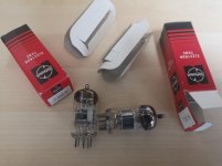
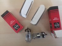
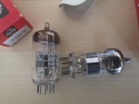
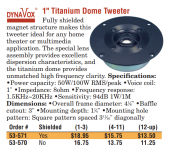
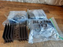
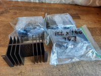
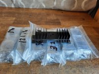
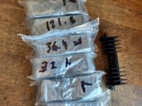
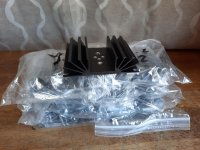
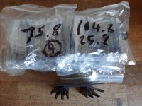
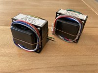
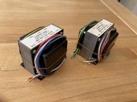
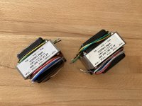
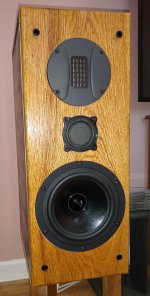
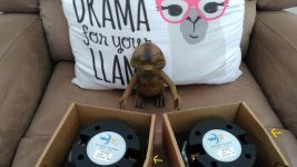
, and its clearly visible on the small HF10AK's packages, luckily they had a nice foam padding there, not Part Express fault though.


Hopefully this is no big deal as I will using them with DSP, and not worry about RMA them.:apathic:

P.S. they will replace a pair of PRV D280Ti-B on LTH102.


Edit: Will do some quick REW measurements side by side and see how they compare though.


Sorry for my English.


Regards!


EDIT: I spoke too early in my last post, I'm currently under an RMA process with PE since the 2~3dB drive sensitivity difference gets even worst(4dB+) the higher the volume becomes, effective smearing/unbalancing the audio image completely, definitely an defective unit unfortunately.

Attachments

  • IMG_20210504_143711.jpg
    IMG_20210504_143711.jpg
    203.8 KB · Views: 275

Audio Control DM-608 Hissing :(

I bought this for personal use. This should be a high-end DSP. AudioControl has been around forever and so I put some trust in them. Has the bluetooth module makes it a better value/expense. Id say this is $800 worth of DSP that I am planning to use personally.

The dang thing has a wicked hissing out of all speakers in my truck. When I physically bypass this DM-608, there is absolutely no hiss what-so-ever.

There are jumpers for ground setup. I tried all three positions (200ohm, isolated, grounded). I also tried 5v vs 10v, and the 10v is even way worse. Unbelievable.

Here is a photo and description from their site on the jumpers:
Where are the jumpers on my DM-608? | AudioControl

Device is using about 20+ JRC4560 opamps.

Device is wired to good distribution blocks like all other amps.

The only way I was able to marginally reduce the hiss was via software, where I notice the hiss only seems to be through the output stages. I was able to bump the input to +12db which adds no additional noise, and then reduce the output stages by -15db. Then the hiss practically goes away but that sure is messing with available bandwidth of control (clipping etc). Plus the hissing is STILL slightly AUDIBLE.

Head unit at all volumes. In fact, I can UNPLUG the head unit at the DM-608 and there hissing is still there. I'm 100% confident this device is causing the entire problem.

I cant believe it especially since this device cost quite a bunch. Anybody have experience with these Audio Control DM-608 DSPs? I'm about to go back to my Rockford DSR1 if I cannot find a solution.

Can a 70's Receiver Compress to Enhance Bass?

I have an old receiver that produces some of the nicest bass and midrange I've encountered, though not the ultimate in accuracy. The sense of almost endless, rumbling low-frequency extension and smooth, relaxed midrange made far superior gear sound thin or uninteresting by comparison. I have a $4000 amplifier that doesn't even get use because of it, and others sold off.

I could never replicate the effect using a traditional digital parametric equalizer, so I'm entertaining a possibility that the receiver could behave like a compressor as a dynamic means of frequency response shaping.

I captured some casual measurements with REW. The levels of these measurements were normalized for comparison, since they couldn't be taken at the exact same levels. Measuring the amp output required a voltage divider network, while measuring the preamp output was done straight to a mic line in, so the levels were different prior to normalizing them.

In the first graph, the power amp section, pre amp section and the two together were tested between 0.5W and 1W, normal listening. Nothing special about the preamp section's response. I wonder if a condition, such as the input impedance of the power amp section was better suited to the preamp's output? Viewing the violet curve, the preamp has more extension when it's connected to the power amp section, but I can't compare levels to see if the response may have been compressed to extend it:

sBzG23v.png


In the second graph, the measurements were also taken at slightly different levels and then normalized for comparison. We see the baseline amplifier reponse again (green), then the amplifier was operated with a real 3-way speaker load (brown). The response follows the speaker's impedance curve, due to the amp section's higher output impedance. It's also like something occurs between the pre and amplifier. I just don't know how to analyze a signal for compression.

RpoK85T.png


Has anyone encountered a low-frequency enhancing behavior like this?
One wouldn't know it rolled off in the bass and would believe there was a 9dB tilt in response, though it's only 4dB as measured.
Projects by fanatics, for fanatics
Get answers and advice for everyone wanting to learn the art of audio.
Join the Community
507,753
Members
7,886,708
Messages

Filter

Forum Statistics

Threads
406,157
Messages
7,886,708
Members
507,753
Latest member
ayodej