I read that a critically damped woofer is 6db down at resonance (q=0.5).
A woofer (ATC SB75-150SL) has a resonant frequency of 57hz, and in the sealed 20 litre SCM20 monitor, the -6db point is 54hz. Does this mean it has a q of just over 0.5 in this system?
The qms and qes of the driver is 0.89 and 0.84, so I'm wondering how it's possible to have a lower q. I believe Vas is listed as 7 liters, and the Cms is 2 (I forget the units). I'm not an expert, far from it, but these values would lead me to expect a sealed enclosure between 4 and 6 liters would be required for this. What am I missing?
Edit: I remembered Qms wrong, it's 7.6. Discussed further in the thread
Last edited:
Qt = 1(1/Qes +1/Qms ) =0.445 (note that the Qms is very low, lower than i have seen on any driver available for diy).
Vas = 7 litres
Fs = 57 Hz
Q = 0.5 sealed box will be 26.666 litres (before damping), add damping — ~22 liters is probably sufficient
dave
Vas = 7 litres
Fs = 57 Hz
Q = 0.5 sealed box will be 26.666 litres (before damping), add damping — ~22 liters is probably sufficient
dave
Qt = 1(1/Qes +1/Qms ) =0.445 (note that the Qms is very low, lower than i have seen on any driver available for diy).
Vas = 7 litres
Fs = 57 Hz
Q = 0.5 sealed box will be 26.666 litres (before damping), add damping — ~22 liters is probably sufficient
dave
There's some stuffing.
I haven't seen one anywhere else either. It's an unusual woofer - 3 inch voice coil, underhung, 20mm gap and (I think) 8mm coil in this rendition. The magnet is several hundred ounces, BI is still only 8. It's their "Super linear" motor, most often attached to a 9 inch cone, but also 12 and 15. It has very low distortion in its linear range. If you google "ATC super linear pdf" their marketing materials give some insight. Most important takeaway is 10-15db less third harmonic distortion from 100 to 3000hzz because of SLMM rings in the magnetic circuit.
I didn't realise I forgot to post the fs. Edit: oops, I posted it. So when I said "You must have found the one page for that woofer in that massive document lol." I was wrong lol. Anyway, I'll leave "The datasheet is sparse... I got the 8mm voice coil height from a review, I'm guessing the reviewer was told by ATC. All the SL magnet assemblies are the same and have a 20mm height, I can't remember if it's on the datasheet either."
Which parameters did you use to calculate the box volume at a specific q?
Which parameters did you use to calculate the box volume at a specific q?
Last edited:
"You must have found the one page for that woofer in that massive document lol."
Hmm, do you mean this one?: http://www.atcloudspeakers.co.uk/wp-content/uploads/2014/01/ATC-Driver-Specs.pdf
I found a SB75-150S 'Super Linear' on pg. 47, but its specs [attached] lists a much higher Qms, Qts, so assuming you've listed Qes, Qms in error, then Qtc based on a ~0.843 Qts:
a = 7/20 = 0.35
Qtc = [0.35 + 1]^0.5 * ~0.843 = ~0.98 Qtc
Factor in some wiring losses, spec variations and it seems reasonable that it's a 1.0 Qtc alignment.
Attachments
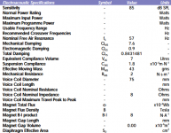
Yes, page 40/47. I couldn't find it and was going by memory when I made this thread - I was quite wrong. I typed things in below for a text version:
Fs 57hz
Qms 7.6
Qes 0.9
Qts 0.8431481
Vas 7L
Cms 1.8
Rms 2
Mms 43 grams
BI 8.0
This woofer has qts of ~0.84, so is absolute maximum q possible in an enclosure 0.84? What volume of enclosure would do this and what would its -6db point be?
Right now I'm working on making these speakers active and lowering the crossover point of the tweeter as low as the 10" baffle allows. It's looking like 1.6-1.7khz/24db is the lowest I can go with this baffle because a suckout probably starts at ~1400hz and continues to ~700hz where it finally ends up 6db down. My target was 1.2khz, so I'm considering making a new box for this reason and now possibly to lower woofer q. The bass doesn't sound sloppy at all to me - I think it's exceptionally detailed - so maybe I shouldn't change the volume of the box to fix a problem that only exists in parameters if it affects low end extension
Last edited:
No, it means that if [Qtc] = [Qts'], then net volume [Vb] = infinite, though more realistically a [Vb] = 10x [Vas] is close enough from a HIFI/HT POV.
Max [Qtc'] is based on smallest [Vb] attainable, so some [small?] fraction of a liter.
[Qts']: [Qts] + any added series resistance [Rs]: Calculate new Qts with Series Resistor
[Rs] = 0.5 ohm minimum for wiring, so may be higher if a super small gauge is used as a series resistor plus any added resistance from an XO/whatever.
I don't quite get what you mean, because you say q of this woofer in a 20 liter box seems to be about 1, and you say in a 70 liter box (or bigger) it would be 0.84? Wouldn't using a smaller than 70 liter box mean then the q would have to be less than 0.84?
Say an enclosure as wide as the woofer basket and as deep as the magnet is made, leaving minimal air behind the woofer. Is qts below 0.84? For some reason I have this thought that the q of the woofer in a box can't be lower than qts, but that can't be right after thinking some. By chance is Q 0.5 if Vas = Vb?
About resistance, I use 8 foot 9 gauge braided cables with gold plated ends, their resistance is quite low - think about 0.1 ohms. I'll have to measure the crossover, but I think its resistance should also be pretty low - apparently there is use of only high quality air core inductors in the crossover. By high quality I assume at least part of that means heavy gauge lol
Sealed box math: Closed Subwoofer Box Equations Formulas Design Calculator fc System Resonance Frequency
a = [Qtc'/Qts]^2 - 1 = [0.843/0.843]^2 = 1 - 1 = 0
Vb = Vas/a = no can do, so we call it 'infinite' for lack of a better description. 😉
a = Vas/Vb = 7/70 = 0.1
Qtc' = [0.1 + 1]^0.5 * 0.843 = ~0.884 Qtc', so close enough to I.B. that our LF hearing acuity can't tell the difference.
a = [Qtc'/Qts]^2 - 1 = [0.843/0.843]^2 = 1 - 1 = 0
Vb = Vas/a = no can do, so we call it 'infinite' for lack of a better description. 😉
a = Vas/Vb = 7/70 = 0.1
Qtc' = [0.1 + 1]^0.5 * 0.843 = ~0.884 Qtc', so close enough to I.B. that our LF hearing acuity can't tell the difference.
Ah, I get it. So in an actual infinite baffle, qts=qtc. And the smaller the box gets, the higher qtc goes.
I'm still confused as to why though, because as qms lowers, the suspension/surround's strength and resistance increases, and qts goes down. But doesn't a smaller box have the same effect as a more resistant mechanical structure?
So why does q go up with a smaller box, but down with a stiffer suspension? Am I missing a parameter which also affects qms?
Correct, once any added series resistance is factored in [Qts'].
Yeah, missing parameters [plural] soon as I saw this it became obvious that I should have posted this back when Dave posted the basic Qt formula: Thiele Small parameters equations - How each one affects the others
If you really want to 'grok' 😉 sealed alignments: R H Small's Closed Box JAES Papers: Read Research - Articles
Thanks for the links, I did some reading last night. I started with vented enclosures first for some reason, then moved to sealed. After some time I came to a realization: this driver's Fs is raised from its free air 57hz point when the driver goes into the box. If fs was 57hz in box, and the -6db point was 54hz, q would be just a bit above 0.5. But because the resonant frequency is probably up in the 70something hz in the box, q has to be much higher (and it is, somewhere around 1).
One thing that I still can't bring myself to understand is why a sealed box raises q, and a stiffer suspension lowers it. When the suspension resists cone movement, q is lowered, but when air does the same thing, q goes up. It's very confusing to me
One thing that I still can't bring myself to understand is why a sealed box raises q, and a stiffer suspension lowers it. When the suspension resists cone movement, q is lowered, but when air does the same thing, q goes up. It's very confusing to me
I think I get why - with increased excursion the resistance of the air behind the cone increases. But with the suspension the same restoring force is present regardless of the cone's position.
Correct? Or no lol
Correct? Or no lol
Thanks for the links
You're welcome!
Again, do the math to find how high it raises [Fc].
a = 7 L/70 L = 0.1
Fc = [0.1 + 1]^0.5 * 57 = ~ 59.78 Hz
This tiny ~ 4.086 % makes sense considering how acoustically large the box is relative to its compliance [Vas].
??? No, we already determined that Qtc only increased the same ~ 4.086%.
Note that this simple math designer I've used doesn't include the stuffing's impact on it, though again, within reason WRT material type/stuffing density it's normally not audible beyond reducing in any box resonances.
For heavy damping, here's some testing to use as a guideline: https://www.ranger5g.com/forum/attachments/box-builder-fill-er-up-pdf.35156/
Don't have any math to calculate F6, only F3, which is on the math page.
Again, look at the math, Qts/Qts' sets Qtc/Qtc', so Qms per se can't lower it; what it does is add 'stiction'/'drag', which for a given Qts/Qts' puts more strain on the motor [Qes/Qes'] as power increases, which in turn heats up the VC, further raising its Qtc/Qtc', making it less able to overcome the box's air mass 'spring' = increasingly under-damped with increasing Q.
What you seem to be doing is just changing Qms, which lowers Qts/Qts', ergo Qtc/Qtc', but it's now a different motor with a much lower Qts.
with increased excursion the resistance of the air behind the cone increases.
True, but until Vb = Vas where compliance = unity, Vas controls, so Vb increasingly controls only with decreasing Vb = increasing Qt/under-damped.
Last night I measured the woofer's resonant frequency in box, and from what you posted above, it turns out the woofer's Fs is probably 46hz, because it's 53.5 in its 20L box (you have 70L in your equation, which I think we were using for a practical IB)
Modifying the equation a bit to give Fs from Fc:
1/(1+0.35)^0.5 * Fc = Fs
1/1.1618 * 53.5 = 46
I read in one of Small's papers that the ratio of Qts to Qtc is about the same as the ratio of the woofer's free air resonance and its resonance in box, like what you said. If my calculation above is correct, Fs is 11hz lower than we thought before
53.5:46 = 1.163:1
46:53.5 = 0.859:1
Which one would we multiply by Qts to get Qtc? The larger one? Qtc has to be higher than Qts, so I'm thinking the higher one.
0.84* 1.163
Is Qtc 0.976?
You said Q was 0.98 before, how come I arrived at the same value as you for this woofer when you had Fs of 57hz on page 1?
Ah, Fs isn't related to Qtc, other than its ratio to Fc is the same as Qtc's to Qts.
The more the resonant frequency rises after a woofer is placed in a box of a specific volume, the higher the woofer's Qts.
In this speaker, the -6db point is almost the same as Fc, and Qts is almost exactly 1 - is this a coincidence, or is Qtc of 1.0 when Fc equals the -6db point?
The more the resonant frequency rises after a woofer is placed in a box of a specific volume, the higher the woofer's Qts.
In this speaker, the -6db point is almost the same as Fc, and Qts is almost exactly 1 - is this a coincidence, or is Qtc of 1.0 when Fc equals the -6db point?
Last edited:
Hmm.......
a = Vas/Vb = 7/20 = 0.35
According to this math program: Step-by-Step Math Problem Solver
53.5 = [0.35 + 1]^0.5 * Fs
rearranges to:
Fs = [53.5 * [0.35 + 1]^0.5]/[0.35 + 1] = ~46 Hz
So we agree, though with my near zero advanced math skills, no clue why it didn't offer your much simpler solution, so thanks for that.
Re Thiele, Small papers, never read them beyond browsing for various specifics nor TTBOMK used the formulas beyond answering yours and a few others Qs recently as a belated learning experience.
Really, my only need for sealed alignments over the decades is IB and designing compression loaded horn drivers [BP4 alignment] where Qtc isn't a consideration, but measured after the fact.
Correct, I proved it earlier, though everything we've done here is based on an empty box, one measurement, so damping [lower Qtc] will change the ratio.
Yes, it has to per the math: 53.5/46 = 1.163 * 0.843 = 0.98 Qtc
But Fs changed, so look at what all that can be changed/juggled to accommodate it: Thiele Small parameters equations - How each one affects the others
Plus we're assuming the 0.843 Qts is correct, which considering the lack of sufficient specs may/likely be bogus WRT your driver, so until you measure them we can only assume this is either a learning exercise and/or one in futility depending on one's POV.
Me, I'm outa here and hope you measure/post the specs for others, including the basic response, etc., plots.
a = Vas/Vb = 7/20 = 0.35
According to this math program: Step-by-Step Math Problem Solver
53.5 = [0.35 + 1]^0.5 * Fs
rearranges to:
Fs = [53.5 * [0.35 + 1]^0.5]/[0.35 + 1] = ~46 Hz
So we agree, though with my near zero advanced math skills, no clue why it didn't offer your much simpler solution, so thanks for that.
Re Thiele, Small papers, never read them beyond browsing for various specifics nor TTBOMK used the formulas beyond answering yours and a few others Qs recently as a belated learning experience.
Really, my only need for sealed alignments over the decades is IB and designing compression loaded horn drivers [BP4 alignment] where Qtc isn't a consideration, but measured after the fact.
Correct, I proved it earlier, though everything we've done here is based on an empty box, one measurement, so damping [lower Qtc] will change the ratio.
Yes, it has to per the math: 53.5/46 = 1.163 * 0.843 = 0.98 Qtc
But Fs changed, so look at what all that can be changed/juggled to accommodate it: Thiele Small parameters equations - How each one affects the others
Plus we're assuming the 0.843 Qts is correct, which considering the lack of sufficient specs may/likely be bogus WRT your driver
Me, I'm outa here and hope you measure/post the specs for others, including the basic response, etc., plots.
- Home
- Loudspeakers
- Subwoofers
- Critically damped parameters