This is a 4 channel class-d amp. The output is highly distorted. It had this issue brand new out of the box. This is my first attempt at repairing an amp. I have been trying to troubleshoot the issue by following Perry's tutorial, which is amazing, but it is a lot of information to digest and I am stuck.
The output is highly distorted at all gain levels, but gets worse as the gain is increased. None of the other switches or knobs have any effect on the distortion. The distortion is the same through both the RCA inputs and audio played through the amp's BT connection. All 4 channels are distorted. When just one (any) RCA input is connected, the audio is present on all 4 channels and all are distorted. The output is a little louder on the connected channel, but is easily heard on all channels.
I have checked the power supply rails at the rectifiers and I see clean rails of approx +40v and -40v on my scope.
I checked for oscillation on the output FETs and I see a square wave that peaks at approx +40v to -40v.
I don't really know where to go from here and could use some direction. Thanks in advance.
Thanks for the reply. I'm not exactly sure how to test that. I've got 2 regulators that are outputting 16v and one outputting -16v that are near the preamp section. I tested the supply voltages on all of the op amps. They all read just under +/- 12v, but the data sheets all have supply voltages rated at +/- 18v or +/- 16v. I don't know if that is normal or not.
If this is a factory defect, it may be difficult to repair, especially without a diagram.
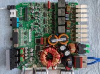
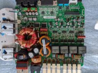
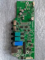
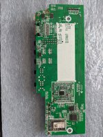
Post a photo of the entire board and any driver boards.
The datasheets for the op-amps simply give the absolute maximum voltages. Some amps use well under the maximum voltages. ±12v may well be OK in this amp, especially since they are about the same magnitude.
Post a photo of the entire board and any driver boards.
The datasheets for the op-amps simply give the absolute maximum voltages. Some amps use well under the maximum voltages. ±12v may well be OK in this amp, especially since they are about the same magnitude.
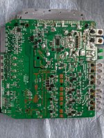
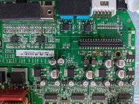
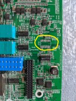
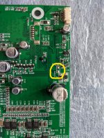
I realize it may be very difficult to find the issue, and that I might not be able to fix it. Here are the pictures of the front and back of the main and daughter boards. I highlighted a couple of spots on the daughter board, U112 and NTC3, in the last 2 photos that appear to be missing components. I don't know if that is normal or not, but I thought it was worth asking.
Attachments
-
 PXL_20210524_185753278.jpg1.1 MB · Views: 229
 -
 PXL_20210524_174230980.jpg1.1 MB · Views: 165
 -
 PXL_20210524_184612001.jpg811.8 KB · Views: 86
 -
 PXL_20210524_174253750.jpg1 MB · Views: 91
 -
 PXL_20210524_174440962.jpg955.7 KB · Views: 99
 -
 PXL_20210524_174502337.jpg863.1 KB · Views: 104
 -
 PXL_20210524_174526105_LI.jpg760.6 KB · Views: 72
 -
 PXL_20210524_174549672_LI.jpg709.3 KB · Views: 91
I couldn't find a diagram (or internal photos) online but the service manual is likely available from Infinity/Harman.
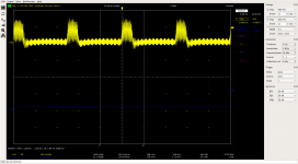
Any screenshots of waveform coming out on o-scope? Is it visibly distorted?
Any cold solder joints on any of the larger parts? Looks like the supply fets don't even have solder wicked through topside. Could be fine but worth checking for poor solder joints.
Any cold solder joints on any of the larger parts? Looks like the supply fets don't even have solder wicked through topside. Could be fine but worth checking for poor solder joints.
Looks like you've got a stray strand of copper wire floating around by the speaker outputs that might cause you some headaches later on.
Sounds like something shorted in the front end OP AMPs somewhere, you’ll need a signal generator and a scope or DMM to locates the problem.
@bnae38 here is what a 1k sine looks like at the speaker terminals.
@mrphreak good eye! Thanks!
@miniman82 I have a usb scope and a couple DMMs. I can generate a signal with my laptop, so hopefully that is sufficient. How do I determine which op amps are the front-end ones?
@mrphreak good eye! Thanks!
@miniman82 I have a usb scope and a couple DMMs. I can generate a signal with my laptop, so hopefully that is sufficient. How do I determine which op amps are the front-end ones?
Attachments
- Home
- General Interest
- Car Audio
- Infinity Kappa K4 distortion