Pioneer PDR-555RW

Hello,

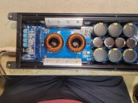
I have a Pioneer PDR-555RW that does not want to load a CD.
The player shows "CD - CD-R - CDRW - CHECK DISC" and that's all.


The error code is:

0255 P6

P6 = The unit does not read the inserted disc and stops. (CHECK DISC display) / TOC READ

84300008

*4 = TOC, PMA read (including SETUP)
30 = TOC area search
00 = -
08 = "Improper A/D value of RFT, RFB"


What I figured out so far:

Having this unit set to the test mode, I have no problems playing a pressed CD. But I am not able to play a CD-R in test mode.
So maybe that is the reason the player is not able to detect the medium?

In another thread, I read about cleaning the TOC Switch S601 but that does not change anything.
According to the service manual, I should check PC651.

Maybe someone has a hint or an idea.


Greetings,
Klaus

Audiosector LM3875 kits (5 kits = 10 channels) + toroids

Morning all,

I have in my possession LM3875 kits from Audio Sector + 330VA toroids (25v).

The kits are fully built and used by the previous owner. I sadly never got around to it. Looking for $100/kit (including the xfmr) + shipping. I can do package deals if wanted 🙂

Attachments

  • IMG_20210516_065109990.jpg
    IMG_20210516_065109990.jpg
    824.1 KB · Views: 454
  • IMG_20210516_065141741.jpg
    IMG_20210516_065141741.jpg
    416.3 KB · Views: 453

SB15MFC 2-way 'The Lockdown"

Had these drivers sitting my shed for months, they will eventually be part of a 3.5 way, but had to see how they sound. SB15MFC -4 & SB21SDC tweeters, Xover 3KHz, in 11 Litres tuned to 44Hz for an F3 of 43. (I didn't use the 0.39 ohm R in series with the tweeter) Sound remarkable, great clarity on vocals, & impressive low mids for Double bass, handle metal (Ningen Isu) well until they are wound up quite high. Really impressed by the MFC drivers.
The 18mm ply boxes are recycled, I should know from experience that it's easier to start from scratch, but I'm genetically programmed as a tightarse. So this evening, time to set them up properly in the room, pour a Glenmorangie, & settle down for a session....

For the 3.5 way, lower mids will be SEAS CA18RLY, and for woofers, not sure possibly 2x SB20PFC, or this Altronics 10";
C3026 - Redback 250mm (10") 120W Woofer PECC Speaker - Altronics

Attachments

  • mfc1s.jpg
    mfc1s.jpg
    97.5 KB · Views: 360
  • xos.jpg
    xos.jpg
    339.4 KB · Views: 343

ICEPower 1000ASP Issues?

I have a number of ICEPower 1000ASP amplifier modules which have been great, however two of the last 3 I've bought have failed.

They appear to struggle to start up like they're trying every second, failing and trying again; the LED flicking green and orange constantly.
Has anyone else had this problem? I'm wondering if there's perhaps been a bad batch lately, etc?

Cheers
Benno

Triode Strapped Curves for 6BM8 Pentode

Triode Strapped Curves generated for 6BM8 Pentode

Hi All,

The 6BM8 contains a high mu line-level triode and medium power pentode (Pa ~7W) in one convenient glass envelope.

I made some rough triode curves for the pentode section. They can be found here:

Triode Strapped Curves for the 6BM8 Pentode – Greg's Stuff

Hope someone finds them useful.

Cheers,

Greg

How To Reduce An Aikido's Gain?

Folks:

About 15 years ago, Bas Horneman hosted a couple of group buys for Aikido preamplifier pcbs (as I recall, this was before John Broskie began selling boards). I built a noval Aikido using Bas's boards and have been very satisfied with that project until very recently, when a few component changes were made to my tube system. The problem now is that the gain is too high, perhaps by 6 - 10 dB.

I'm no expert in tube topologies and have no clue as to how to reduce the gain on my Aikido. For me, the ideal solution will be as simple as possible and will not degrade the sonics of this preamp.

In my Aikido, T1 are 6N1P and T2 are 6H30. Would swapping or replacing the tubes be a solution?

Your advice is greatly appreciated!

Regards,
Scott

Attachments

  • Aikido Preamp & PS (front view).JPG
    Aikido Preamp & PS (front view).JPG
    71.1 KB · Views: 442
  • Aikido Interior (with tubes).jpg
    Aikido Interior (with tubes).jpg
    469.6 KB · Views: 391
  • Aikido interior (full with tubes).jpg
    Aikido interior (full with tubes).jpg
    345 KB · Views: 398
  • Aikido Schematic (noval).jpg
    Aikido Schematic (noval).jpg
    157.4 KB · Views: 433

Subwoofer driver recommendation

I am looking for a subwoofer driver recommendation to be used in a custom sealed enclosure in my Jeep Wrangler.

A link for the enclosure:
2007-2018 (Passenger Side) Jeep Wrangler JKU 10" Rhino Coated Subwoofer Box Sealed-Sold in singles. - BRP AUTO DESIGNS

They make enclosures for a 10-in and a 12-inch subwoofer. Both enclosures have 0.75 cubic feet of air space. I am going to be powering this driver with the subwoofer channel of an Alpine pdr-v75. The amp produces 250 watts at 4 ohms and 350 at 2 ohms. So unless there is a significant efficiency advantage for the 4 ohm driver I'd like to stick with drivers that are capable of providing a 2ohm load. My primary goal is to provide balanced sound through the system and I would prefer low-end extension and musicality over total output.

The modeling I have done so far shows that a good performing 10-in subwoofer will provide better low-end extension in the small sealed enclosure that I am confined to without a bunch of eq.

The best driver I have found at the moment is this.
Dayton Audio RSS265HO-44 10" Reference HO DVC Subwoofer

Price is not a huge concern but I would need significant convincing to spend more than $200 on the driver. I have been out of the audio game for several years now and I'm open to suggestions. I'm also completely open to a 12-in driver if I can make it work, perhaps I'm running the modeling wrong as it seems counter-intuitive that a 10-in driver would provide better low-end extension. Thanks in advanced.

Interesting ways to mount toroidal transformers.

I'm ordering parts for a 6L6 PP UL amplifier. I'll be using a toroidal transformer.
I would like to see some different ways people have mounted them. I've used the metal pill box, square covers, etc. I would like to mount it vertically this time. I've seen the U shaped and L brackets. But I would like to do something different. I want to maybe use rod end bolts. One on each side with a bolt going through the middle of the transformer. But I can't find anything like a 5" diameter shrink tubing to cover the mylar covering of the transformer.
I would like to wind up with a more finished look. I've been looking for something like a plastic clam shell to cover the windings. So what have others here done to mount a toroidal transformer vertically?

Usher R1.5 Bias adjustment from 42c to 50c

I have an Usher R1.5, from what I read, it is a close copy of Thresholds/Pass' Stasis S300 amp. The Usher is 50 watts Class A / 150 watts Class AB

To get 50 watts Class A, I would need to bump up the bias and ensure that the heatsinks are at 50c. When I got my amp, it was idling at 36c. My infrared thermometer's upper limit is 42c, so I biased the amp up to 42c. New infrared thermometer with 100c upper limit is on order. I am familiar with Nelson Pass' 10 second hand rule on measuring temp on the heat sink, but do not want to take a chance right now 🙂

Will there be a noticeable improvement in sound quality once I get to 50c?

What happens if a put two small fans on each side to cool the heatsink, aside from cooling the heatsinks, will it have a negative effect on sound quality?

NAD 6155 Cassette Deck, Transformer PTX-263E prim.coil fried

Hello,

I've a NAD 6155 C-cassette player dated back to 1986, with a power transformer which I fried few days ago (too hot hereabout for its primary winding...). And as one may guess finding spare parts seems to be quite a problem. Based on the schematics (or rather the voltage ratings of the ripple capacitors) I've guessed that it has a 2-winding secondary with outputs of 12V-0V and 24V-0V-24V. My question is that if there happens to be accurate voltage readings for this transformer, if it's a common type (PTX- 263E) or taylor-made for NAD , and what if it's replaced by eg.t wo toroid trafos, one cnter tapped 24V-0V-24V, and another 0V-24V. Based on the fuses, 500mA only, these are pretty small and fit well in the original sheet metal box. It seems that multi-tapped transformers are quite difficult to find nowadays.

Attachments

  • NAD6155_trafo.png
    NAD6155_trafo.png
    712.9 KB · Views: 138
  • 20210624_205913.jpg
    20210624_205913.jpg
    753.2 KB · Views: 133

93C46 EEPROM Corruption on EM8810 E-MU 1820/1820m/1212/1212m PCI Card?

Looking for some advice on a failed EM8810 PCI Card. That is the PCI card for the E-MU (Creative Professional) 1820/1820m and also can be used with 1212/1212m.

In systems where it previously worked (with all the W10 driver fixes) it is no longer recognized by the driver installation. It shows up in device manager but not as the EMU E-DSP. It is now an unknown device from unknown manufacturer. Just FYI the same (multiple systems) still work fine with my EM8960 PCI card for my 1616m. So I believe the software/drivers/machines are ok.

With quite a bit of searching I came up with someone else (in Russian) with a similar problem that they fixed on their EM8810 by reflashing the 93C46 EEPROM. It seems that EEPROM corruption occurs sometimes with the EM8810 (E-MU 1820/1212) and some other Creative products (such as AWE64).

My searches reveal EM8810 EEPROM corruption here: (See post 53) [I used Google Chrome to translate to English.]
??????? ???????? ? E-MU 0404 PCI - ???????? 3

And AWE64 EEPROM corruption here:
Creative PnP EEPROM collection \
VOGONS


Does anyone have any experience fixing such a problem? I am thinking of trying to use an Amazon CH341A EEPROM programmer with a clip.

The EM8810 board has a "CSI 93C46S" which I believe is a 5V CAT93C46S (Catalyst) EEPROM.

I probed the Vcc and GND pins and they are connected to what appears to be the 5V and GND pins of the PCI card. (5V being the last pins furthest from the bracket on the 32-bit card.)


Should I hazard this repair attempt (this way)? Or should I de-solder the chip and program it off the board to be safer?

I have attached a picture of the programmer and of a EM8810 PCI board.

Attachments

  • EM8810.jpg
    EM8810.jpg
    282.8 KB · Views: 298
  • CH341A Programmer.png
    CH341A Programmer.png
    442 KB · Views: 374

Did someone worked with Peerless/Tymphany PLS-P830985 ?

Did someone use Peerless/Tymphany PLS-P830985 ?

Hi everybody.
This is my first real project and it didn't gone well.

I purchased 2 Peerless PLS-P830985, 2.5 inch,
and made boxes (plywood, 12mm) with 1.6 liter inner volume.
Speakers mounted from inside.

I haven't made a port and sealed them properly yet, as I'm waiting for some router bits.
But I have just assembled the thing, and it sounds like ... crap.
Ok no bass - that's predictable. But the sound in the middle is somehow not "opened" and the heights are the worst. Especially in dancing music the beat with "ts" and "ch" almost hurt the ears. And it looks like these drivers play these sounds "ts" and "ch" even if they are not in the music.

I first tried them with D-class amp (cheap amp from aliexpress, works from usb, 2*3 Watt, I don't recommend it either). Then with my good-old Rotel RA-935BX and compared against B&W 602.5.
Again, no comparison of low frequencies, but the rest also just sucks.
The worst is that the sound is very unpleasant for the ear.
Some small multimedia from Microlab/Sven/Edifier for comparable price would be waaay better.

I'd like to hear other experiences with these speakers. Am I doing something wrong?
IMG_20171119_180326.jpg


image.png
[/img][/url]

Technics SL-M1 pitch issue

I could use some help solving an issue with the pitch control on a Technics SL-M1.

To start, the service manual I have for the SL-M1 doesn't show a pitch control or the associated circuit, which leads me to believe that this feature was added to later models. So I'm flying a little blind here.The circuit in the SL-M2 appears to be similar, so I'm basing what follows off of that.

The issue is that I can't center the zero position on the pitch control. Per the service manual for the SL-M2, with the pitch slider (VR401) at zero and a frequency counter connected to test point TP27, you should adjust VR301 for between 262.075 kHz and 262.085 kHz. The closest I can come is 250.833 kHz, and that's with VR301 all the way clockwise (zero ohms). Of course, if I move the pitch slider from the physical center position, I can get the frequency dialed in correctly, but not until the slider is nearly all the way to the left.

This circuit is also similar to that of the Technics 1200 MK2, though neither the SL-M1 or SL-M2 have a pot for adjusting the pitch control gain like the 1200 does.

I've cleaned the fader with Deoxit F5, and it acts the same as before.

More data, FWIW:

IC301, pin 2: 1.9V
R301: 1.49k ohms

Attachments

The Intellectual People Podcast - KLOS Guitars

Adam explains to us about the formation of KLOS Guitars and how they're made. He and his brother Ian's formal education of Electrical & Mechanical Engineering have certainly helped their journey of KLOS Guitars. They have also started a company called Skill Board USA for the ultimate in human balance control.

Carbon Fiber Guitars | KLOS Guitars | Skill Board USA | Ep 33 - YouTube

Attachments

  • 1.jpg
    1.jpg
    119 KB · Views: 104

Sizing PT and rectifiers

I'm using bench supplies to prototype an amp design, and I'm about ready to move on to the power supply. Plan is 400V B+, 350V drivers, and 250V screens. B+ and screens will each have a simple MOSFET-based series regulator with their own VR tubes for voltage reference, and the driver supply will pull from the B+ with an RC filter. The PT will be set up as full-wave, with a zener string in the center tap connection for bias supply.

I've verified these current draws using an inline ammeter set for DC amps:
  • 160 mA plates
  • 35 mA screens
  • 10 mA drivers
In addition, I'll be sinking ~10mA apiece into the two VR tubes. So by my math, that's 225mA total.

When I modeled it out in LTspice, RMS current at each rectifier diode was over 400 mA. So, questions:

  • Which current figure is the correct one for sizing the transformer? IOW, is a transformer like the Antek AS-3T350, rated for 400mA per HV winding, sufficient?
  • Which current figure is the correct one for sizing the rectifiers? I'm looking at using a pair of 6DM4A, a diode rated at 200mA continuous.

Thanks!

Using an integrated amp as a power amp

I have a Haffler DH220 that I want to recap. While I'd doing that, I'd like to use an integrated amp to replace it. The Haffler will likely be on the bench for a few weeks while I make a parts list, order parts, and in general find the free time to do the maintenance on it.


I'm pretty sure I can just run a pre-amp into an input on the integrated amp and set the volume control on the integrated amp to some fixed level (say 3/4).

In looking at the schematic for the input section of the integrated amp (first attachment), it looks like the signal pass is from the input to a buffer (2604 op-amps, U1A/U12) and then to the attenuator (the LM1972, U22). The outputs from the attenuator go to another set of buffers and then on to the amplification stages (2nd attachment).


Since the LM1972 only attenuates and doesn't have any gain, this seems like a safe bet....but I thought I'd check first.


Thanks,


James

Attachments

  • Screenshot from 2021-07-03 08-11-42.png
    Screenshot from 2021-07-03 08-11-42.png
    218.2 KB · Views: 160
  • Screenshot from 2021-07-03 08-08-34.png
    Screenshot from 2021-07-03 08-08-34.png
    253.3 KB · Views: 144

Repairing the op-amp power supplies in Primare I20..cap reccs?

I'm new to audio repair, but not to electronics in general and built a headphone amp once.

Anyway, i decided I wanted to learn to repair amplifiers so I picked up a "for parts or repair" Primare I20.

It would power up and the display and pre-amp section seemed fine, but had no output.

Once I had it home, I started testing the voltage at the test points on the board. My guess was a power supply issue as this is a dual mono amp and other than the pre-amp, nothing else is shared across both channels.

The -14v supply was low (high since it's a negative supply?) at almost 0v. I also notice the +6.1v supply was low at about 1v. at a 7v test point right before the zener.

Checking the voltage at the input of the negative voltage regulator, I had close to 0v. As a comparison, the positive regulator had about 36v at its input. Voltage before R2 was -40v. I removed C8 as I assumed it was shorted. After doing that the input voltage jumped to -36v, but the output was still low at about -7v.

I removed C34 and that fixed the output voltage issue.

Moving on the the +7v supply, in similar fashion I removed C10 and that fixed the problem.

So I have 3 caps to replace C8 and C10 are both tantalum caps, and C34 is an aluminum electrolytic.

I have 2 questions:
  1. Any brand recommendations for capacitors. I think I got a pretty good deal on the amp ($180) and the cost of better caps isn't going to break my budget.
  2. Is there anything else I should be checking? From the schematic, it doesn't look like there is much around these caps to check. The resistors seem fine. I also believe the diodes are fine and they seem to be there to protect the regulators from reverse voltage. I'll order some regulators since they are both relatively cheap and common and will likely get used on some other project if not needed here.
My plan for this is to use it to replace a Haffler I want to recap. Then maybe I'll sell it as I'm hoping to pick up something else to work on.

Attachments

  • 14vpowersupply.jpg
    14vpowersupply.jpg
    114.4 KB · Views: 302

BMW/Alpine stereo very hot

Hi


we replaced a couple of capacitors in a BMW 325is stereo. One was bad. The sound is good now but the heat sink at the back of the unit gets really hot after about 15 minutes of playing. It's made by Alpine I understand. I didn't put any new heat dissipating paste on when we reassembled the deck. Could that be the reason or can there be anything else? Thanks for any advice


Peter

JTM45 rectifier failure

Reposting (sort of) from Tubes/Valves -

Hi all,

I have a 3-year old JTM45 Metropoulous/Valvestorm kit that had a failure of the rectifier a week ago. It also took out one or both output tubes (KT66's).

This is the second time this has occurred, but the first time the output tubes were OK.

From what I have learned on the other forum:
1. Do not use standby (because of cathode stripping?): Already aware of that, I almost never use standby
2. Excess capacitance causes excess surge current at power up this. I am using the standard Marshall design, 32uF before and after the choke. This might be too much for a modern (sic) 5AR4?
3. This amp for some reason has pretty high B+ of 500VDC but that has not been flagged as an issue.
4. There are better 5AR4's that the Sovteks I have... I have read that there are some good chinese ones...

From the advice I received and reading more I see a few options:
1) reduce the capacitance prior to the choke for 32uF total
2) install resistors (47ohm) between the transformer and plates
3) install thermistor (Amphenol CL-90) either on the primary or secondary side of the transformer or in series with the standby switch
4) Use a different rectifier brand (which I really don't want to do as I have two brand new Sovteks.

Is there any other know solution to this issue? My inclination is to try 1) and 3) on the primary side together.

TIA/Tim

Using a ton of smaller woofers for bass ...

I can't seem to find anything about that subject either here or on tubes ,
would be greatful if you knowledgeable guys could chime in a bit on that to enlighten a total noob as meself 🙂

So simply, what would be the result of using a large quantity of smaller diameter woofers or midranges against using traditional single dual or few pretty large woofers/subwoofers .

Not trying to go into specifics here, only trying to understand how all this works slowly so my little brain can process it one bit at a time :spin:

This questioning came to mind when trying to understand relation between mass of drivers ( moving mass ? ) vs speed and sound pressure .

Wouldn't a multitude of lower mass drivers have better response and decay than a much larger single unit for the same perceived volume ?

Thanks for your time 🙂

my first guitar amp - the Lil Champski 5E1

Greetings, Friends. I'd like to share a few pics of my new amplifier.

k9SMgPdl.jpg


I've been dabbling in tubes since last spring and after building a few phono preamps and power amps I figured I'd try to build a guitar amp, and where else to start but the Champ 5E1. This one's tiny, a 12x12" box made of 1x6 with a 6" Jensen Mod speaker. The Speaker had to be offset from center quite a bit to accommodate the iron on the back of the amp chassis, and the baffle is two pieces of 1/4" Fir plywood glued together. It's tight in there. Chassis is a Hammond box, 1444-12 7x5x2" but next time I'll get a 1444-14, 9x5x2" for a little more room.

2zCrQOEl.jpg


I decided to mix things up by substituting the regular output and preamp tubes for their Soviet counterparts, having built up a stockpile of them through the purchase of DIY kits available from many online resellers. The rectifier tube is still the 5Y3, but the output is a 6p1p and the preamp tube is the 6N2. I had been under the assumption that the 6p1p had similar numbers to the 6v6 and built the circuit to spec with a Hammond 290ax PT and 4h choke and 8w SE OPT from a custom builder out of St Louis. All 3 EL caps are 10uF 500v and I was seeing 320v at the first cap, 315v at b+ and 310v on the plate of the 6p1p. Perfect for a 6v6, but now that I can read tube charts a little, I think the 6p1p isn't meant to see more than 250v on the plate.

noAiz2ul.jpg


So I need to drop the b+ enough to get to a safe operating point for the 6p1p. I've seen on a few forums that the old Winged C tubes can take plenty of abuse, but I don't wanna kill them early either. I've put a pair of 270R 6.5w power resistors on the HV lines going into the rectifier and that got the plate voltage down to 295v, b+ at 298v. I'm not seeing any red plating or anything like that, and the amp sounds good at the volumes I can get away with here at home. What would you do? Any other advice?

thanks!

TPHH9ptl.jpg

Diy Bench power supply Oscillating with Inductive load.

Hi
I have been woking on a bench power supply for the past two months or so.
I decided on a discrete regulator design with adjustable voltage and and current limit.
Yesterday I boxed most of it, and decided to test using a couple of parallel connected 12V car bulbs. The bulbs were flickering slightly. Scoped the output and revealed a 16- 25HZ almost square wave/ round edges type oscillation or motor boating.
If i turn down the current limiting it gets even worse.
With my DC load all works as it should.
My electronics knowledge doesn't stretch as far as to fix this. The sense leads come together at the croc clips of the output leads. So there are four wires coming out of the box. The negative output terminal connects directly to neg of main filter caps.
Connecting a 4700uF capacitor across the leads at the load doesn't help much.
Any ideas? See schematic attached.

Attachments

Tube Ambiance Processor Project

I thought I would post this project of mine. This is a tube ambiance processor. It is the same principle as the famous Hafler box of the 1970s but implemented at line level using tubes.

It was built from junk box parts. The only draw back is low gain - the unit is very lossy on it's output but you can probably fix that by changing V2 to a 12AX7 and also it's resistor values. I just made up the gain in the mono amp following this unit.

A relay was used as the null bypass switch to keep the program audio paths short and restricted to the rear panel.

I like the effect. I have four dipole surround speakers that serve double duty with the TV AV receiver. I just series/parallel them for 8ohms when on the tube amp. I use a DIY 6BQ5 PP amp that puts out 10 watts max.

Try it if you like. Also any design comments are appreciated. As for the purists, yes I know, you don't want tone controls or gimmicks like this in you system. But that device can be simply turned down or off if the effect is not to your liking in a particular track. Like any audio enhancement device less is more. The effect is subtle when adjusted properly. You should not be able to pin point the surround speakers sound wise. Otherwise the surround level is too high.

Attachments

  • Tubesurr4.jpg
    Tubesurr4.jpg
    226.2 KB · Views: 170

Side-mounted woofer question

After reading up on side mounted woofers, it seems the consensus is that they work fine if crossed over below 200 hz or even lower. My question is if it is preferable to have the side woofer mounted closer to the baffle, or if it doesn't matter.

I picked up 2 high quality 1" thick plywood cabinets from a thrift shop, for $40 each. The overall dimensions are 16" wide x 24.75" deep x 32" high. There is a 3" raised plinth on the bottom, so the inside dimensions are 14" x 22" x 27". The difference is accounted for by some round-over trim I will remove. These are rabbeted, and heavy duty. I will make a new baffle, and use them in an on-going project for a high efficiency speaker. I plan to brace them extensively.

Years ago I bought a bunch of TAD drivers, and have some gorgeous 1201h mid bass sitting on the shelf, NOS. I'd like to mount them high on a new front baffle, and find something to use on the side that can keep up with the TAD 100db/1w/1m. I have some DIYSG 15" Eminence "buyout" custom woofers, but their efficiency IIRC is about 88db. Dual side mounted woofers for force cancellation would be really fun, as long as price is reasonable. The TAD would be run from about 150-200hz up to 1000hz. Above that would be another box, yet to be determined. I have JBL horns I can mount quickly and give a listen.

These would be well out from the walls in a 23' x 22' x 9' room. Not ideal. Listening position about 10' from speakers.

Are there specific issue I have to avoid in this scenario? Thanks!

6 channel amp - run 240V feed from breaker box?

Have a question for those with expertise in this area...

I am planning an active 3 way system with 6 channels of purifi amplification. I know that the smps used for these modules can be configured to run on 240V as well as 120V. I am in the US and have 240V available at my breaker box. I am pondering running a 240V feed to a 240V outlet and running the amps with the smps' set at 240V. I would use powercon plugs and a 30A breaker in the breaker box. I thought this would make more sense than running multiple circuits to multiple outlets.

Any cons to the idea?

Advice needed: 0.47 uF film cap DC for tube output

Hi,

I need please an advice for a 0,47 uF film cap as DC blocker output for a DAC. Typically : E188CC or 6N23PE-EV outputs.

I thought about : a NOS Philips styrenes that are lead foilded if I remember, but too much dry sound in serie ?

Nos ERO KP ?
Nos ERO MKC ?
a soviet teflon or a soviet paper in oil ?
break the wallet and a modern Miflex copper ?
I also know Torsten Loesch appreciated the Solen leads for the purpose ?
Etc...
Your experience welcome, no money for a Tango transformer, Lundhall, etc !

Many thanks :wave:

Neg Speaker Binding Post QSC PL 6.0 PFC

I need to replace a broken speaker binding post from my QSC Powerlight 6.0 PFC amplifier. It is the black negative post that broke off. I attempted to weld it back together but that was unsuccessful.

The service manual describes the part and part number.

CO-000146-00 BINDING POST, SINGLE, 1 POS, FEMALE, 60A BLACK

I am asking here because QSC parts said this item is discontinued and out of stock.

I have been unable to find a suitable retrofit. So I'll need to get spares from a donor unit most likely.

BindingPost1.png

Speaker Placement Rectangle Room

Hi Everyone,

I'm moving into a place and need to decide which is the best wall for my speakers and listening position. All the advice online shows enclosed rooms, which doesn't help with real world open living floor plans.

Do I place on the short or long wall? I have some difficult doorways and kitchen etc.

I intend to have two bookshelf speakers (B&W 805) on stands and a 3 seater lounge in this room. I also want to install panels to first reflection points and possibly ceiling.

I've attached a layout and some photos from the realestate listing.

Really appreciated your input.

Attachments

  • Screen Shot 2021-06-13 at 9.21.21 pm.png
    Screen Shot 2021-06-13 at 9.21.21 pm.png
    294.7 KB · Views: 220

Is it possible to replace the OPT with different specs for 300B PSE?

I used to ask Patrick 2 years ago with questions but recently haven't heard from him. Hope, he is doing well.

In his reformed Jadis 300B PSE, he used Hammond 2k5 impedance. Can I use Edcor CXSE25-1.25K impedance so I can remove some of the parts on the output transformer? Even Hammond has 1.25k impedance OPT but he picked 2.5k.

Patrick's website: jadis-300b-reformed

Jadis-SE-300-B-OPT.png

Best AMT on the market ?

Hi all

Long time that I don't post/interact here on this forum.
Basically, after I found my dream duo, Beyma 12P80nd/TPL150, i lost interest in DIY, and just so in trying out new stuff.
Thats about 8,9 years by now.
Wondering: Since then, has there be launched any AMT mid-tweeter that tops the Beyma TPL-150 in terms of performance, in special low distortion, and naturalness/neutralness/transparency?

Otangelo

Amplifier LF Peaking in Ltspice

Hello .Just playing with this old amplifier schematic in LT Spice and gives a low frequency peaking.How dangerous is this in real life?It has to do with the different R-Cs and low corners that are close to each other but how to find the and eliminate it?

Attachments

  • 1.jpg
    1.jpg
    156.3 KB · Views: 171
  • 2.jpg
    2.jpg
    391.4 KB · Views: 159
  • s210.asc
    s210.asc
    8.5 KB · Views: 62

Too much MDF... help me build some boom

Long story short, I have a buttload of MDF, mostly 3/4" but also some 1" and some 1-1/4" Then last week I received a couple crates of high-end lumber that was packaged in 3/4 MDF, so I now have two huge 72" x 64" sheets to add to the pile.

I work for a performance theater and I've been craving more boom than my single Yorkville gives.

I have a very large shop

1 + 1 = 2. Let's make booms.

Wants:
Size - not really an issue. For once I have plenty of space for something with volume, so something like a tapped horn or bandpass isn't out of the question.
Freq - basement. The rest of my pre-amp equipment is all good for down to at least 10hz (not that I need that low), and there is just something about a good shake from 17hz when I have a thunder sound effect. The Yorkville does great in the upper 30s, So shall we say 18-40hz?
Budget - technically zero, but I have the MDF and materials to build it. Drivers will likely cost money, but I have a guy who might want to trade me some drivers for a snake I have. Having said that, if I have to buy drivers it seems like a huge jump to go to 18s, so maybe 15s would be wiser.
Amp - up for debate. I would love to splurge on a plate amp. Running XLR to it will be easy. Running speakon from the rack will be a pain. Truthfully I could probably just do a rack mount amp screwed to the box somewhere.
Appearance - ugly. It will be hidden under the seating risers, or possibly even under the stage.
DB - doesn't need to be insane. Most of what we do is live performance theater and musicals. We do occasionally have musical concerts, so having some louder potential will be nice, but no need to make it louder than the Yorkville.

So let's talk. Links? Ideas? Designs?

Soft Start Circuit Help

Hello Everyone,

I'm planning to put in a soft start circuit for the class A/B amp I am building now, which has 2 x 350va toroidal transformers and total 80,000uF of smoothing capacitance (20,000uF for each power rail).

I want to go on the safe side and the one by Ron Elliott seems to be a decent and simple enough one to build. (see figure 5 on Soft-Start Circuits)

Ron's notes suggest that the soft start time is 100ms, but I am thinking of increasing that to 500ms to 1sec, but I am not sure which component / value to change to enable a longer soft start time.

Can someone help me with some advice?

Many thanks and have a safe weekend.

Need help with a DAC build (Bloodac 4 x TD1541)

Hey All,
I recently acquired a Bloodac 4 x TDA1541 DAC board and 4 TDA chips. I've been trying to complete the project but I'm very new to DIY and need some assistance. I reached out to FMs that have previously built this board with no reply (maybe my mistake of reaching out through DMs directly).

I have also reached out to the seller of the board Raindrop Hui but haven't been able to get the design files yet.

From the board I can see that some of the regulators are missing heatsinks and a capacitor is missing. I have ordered the missing components already. I'm trying to get it to working condition before doing some tweaking (Lampizator has mentioned a few upgrades for the board).

One question I have with going ahead is related to the toroidal transformer that I should use for the board. The board itself has 2 x 11VAC and 4 x 18VAC inputs so I'm not sure what transformer to pick/buy. I contacted a local transformer maker and they asked me what amperage I want on the secondary section. I'm not new to electronics but I'm very new to DIY audio so I wanted to start a thread here to get some help.

I have attached images of the board and the link to lampizators post is: fourTDA_dac

EDIT: Link to board images Bloodac 4 x TDA1541 - Album on Imgur

Balanced BA-3 w/Salas Regs, Dual Mono and Goldpoint Volume pot, Fully Assembled

Hello, I built this a couple of years ago to go with a pair of balanced F4's I built.

I used top-quality parts throughout and the result is a really nice preamp. I've been using a pro mixer/audio interface as my preamp since moving to active crossover speakers and the BA-3 has been on the shelf in my climate-controlled shop. I'd love for someone to get some use out of it; easily the best active preamp I've ever listened to.

I'm in Southern NH USA and will happily meet anyone within 100 miles of Manchester. Otherwise, I can ship double-boxed anywhere at the buyer's expense.

It's pretty heavy with the dual toriods so shipping won't be cheap to Europe or Asia.

Asking $1,000+shipping.

HT ss stabilized

Hi

in attach the test on FFT by AP about the HT voltage just after the bridge, around 350 vdc with 330 uF as filter cap and bridge of 25A.
Then at the output of HT stabilized circuit I normally use.
The current is 20 mA ( is a line tube stage).
The results is interesting.

The attenuation on region from 30 to 2kHz is very fine.
At 100 hz the difference of the two peaks is 100 dB; same for the other multiplies (less or more)
Personally in each stage, line or phono, I use this one because it helps a lot also for s7n.
In additon the screenshot from scope on wave at input of board, in out and the residual

Walter

Attachments

  • HT_input_out_stabilizz.pdf
    HT_input_out_stabilizz.pdf
    32.9 KB · Views: 149
  • HT_input_bridge+330uF_325vdc.jpg
    HT_input_bridge+330uF_325vdc.jpg
    88.9 KB · Views: 333
  • HT_out_stab.jpg
    HT_out_stab.jpg
    43.5 KB · Views: 332
  • Scope_residual_input_short.jpg
    Scope_residual_input_short.jpg
    43.1 KB · Views: 325

Hifonics class d,problem with the high-side gate signal

i have a problem with my hifonics brutus bxi 1100d.after output fet failure,the gate signal of one high side bank is not clean and the fets get hot(the two with the heatsink).the other high side and the other both low side gates are ok.i replaced the fets,the gate resistor,the hip4080,the lm393 left of the hip4080,the lm833 and the 6,2v zener diode"ZD1".this diode gets relatively hot,about 100 degrees.on another amp its only 50 degrees

the amp works,but sounds distorted.see the photos.pic 175705 good gate
pic 175712 bad gate
what could be the problem?

Attachments

  • 20210630_175335.jpg
    20210630_175335.jpg
    1 MB · Views: 131
  • 20210630_175434.jpg
    20210630_175434.jpg
    1,001.9 KB · Views: 122
  • 20210630_175526.jpg
    20210630_175526.jpg
    1 MB · Views: 123
  • 20210630_175705.jpg
    20210630_175705.jpg
    655.2 KB · Views: 115
  • 20210630_175712.jpg
    20210630_175712.jpg
    676.7 KB · Views: 111

problem with the high-side gate signal

i have a problem with my hifonics brutus bxi 1100d.after output fet failure,the gate signal of one high side bank is not clean and the fets get hot(the two with the heatsink).the other high side and the other both low side gates are ok.i replaced the fets,the gate resistor,the hip4080,the lm393 left of the hip4080,the lm833 and the 6,2v zener diode"ZD1".this diode gets relatively hot,about 100 degrees.on another amp its only 50 degrees

the amp works,but sounds distorted.see the photos.pic 175705 good gate
pic 175712 bad gate
what could be the problem?

Attachments

  • 20210630_175335.jpg
    20210630_175335.jpg
    1 MB · Views: 140
  • 20210630_175434.jpg
    20210630_175434.jpg
    1,001.9 KB · Views: 167
  • 20210630_175526.jpg
    20210630_175526.jpg
    1 MB · Views: 136
  • 20210630_175705.jpg
    20210630_175705.jpg
    655.2 KB · Views: 127
  • 20210630_175712.jpg
    20210630_175712.jpg
    676.7 KB · Views: 122

Negative feedback and distortion

In this Wikipedia article:

Tube sound - Wikipedia, the free encyclopedia

it is said that negative feedback causes inter-modulation distortions but the references are unreachable.
Can someone give me some serious references that explain this phenomenon and maybe model it, etc. ?
I am curious if this type of distortion is the reason some audiophiles reject the circuits with negative feedback. Maybe they are onto something ? 😕
Any comments and ideas are appreciated.

Distortion vs Global-Feedback (simulated)

I have made the amplifier with separate voltage amp stage and power buffer. I don`t have measurement tools so I simulated distortion vs global NFB.
Input voltage amplifier has local 6dB feedback loop and it is constant. Only global feedback loop around buffer is changed for different data:

On the graph X axis is 2nd, 3rd, 5th and 7th harmonic. Fundamental is 20KHz.
On the graph Y axis is distortion %.
Separate colors are for 0dB, 7dB, 12dB, 14dB and 22dB of GNFB.

Attachment is block schematic and chart data, it might be interesting to someone 🙂

Input stage is complementary jfet/bjt and the power buffer is a all bjt triple EF.

P.S. Interesting thing is there is no 5th and 7th harmonic rise with raising feedback factor as some are advocating...

Attachments

  • block-schematic.jpg
    block-schematic.jpg
    34.3 KB · Views: 432
  • hs-vs-dist-01.jpg
    hs-vs-dist-01.jpg
    180.7 KB · Views: 428

THD measurements

Hi,

I’ve done some THD measurements on my breadboard 6SN7 - 6SN7 - EL34PP project. THD measures 0,39% with 36 Watt output. Now my signal generator has 0,10% THD for 0,32 Volt PP input. My USB audio input also has approximately 0,10% THD.

What THD figure is “real” for the amplifier part only? Should I calculate 0,39 - 0,10 - 0,10 = 0,19%?

Regards, Gerrit

How to measure THD

I am one of the ones who learned electronics backward. First I learned how to fix them then I learned why what I did fixed them, so there are holes in my education. To the point. Recently I completed a very nice sounding 20WPC all triode power amp using 6AS7s for the outputs.🙂 I then bought a used HD Meter and a new Audio Sig gen speced at .018 % HD. The meter confirms the Generators output. So I decided to measure the stage by stage distortion in the amp (it has no feedback). The first voltage amp showed a distortion of 0.4%.🙁 It is one section of a 12AX7, 180 plate supply, 82K Rp, 470 ohm Rk, 470K Rg, with a .04 input and output coupling caps and a 2 ufd Ck. Measurement shows a Vg of ~40 ( 50mv in 2V out). with .4 % distortion.

I then breadboarded that stage. Yep .4 % is as low as I can get it at any reasonable amplification factor.

Now the questions. Is that an unusual amount for one stage? Are HD artifacts additive as you add stages. I assume they are? My Dyna PAS2 specifies HD as being "below that measurable by (back then) modern equipment." To me 0.4% means if I had 4 stages like the 1 stage in my amp the distortion for the amp would be ~1.6 %. What am I doing or thinking wrong? Is .4% a good number for one amplifier stage? 1.6% (.4 x4) is certainly not a good figure for a preamp.😕 Its all very possible that I should quit nit picking and enjoy its openness and what I describe as clarity.🙂

Thanks
Ned

NAD 2150 with swapped Transistors

Picked up a NAD 2150 recently. Sounded good, seller said it was all original. Brought it home and opened it up, and looks like 2 of the Sanken Transistors were swapped out with Toshiba (and a messy soldering job).

This goes a bit beyond my knowledge... anyone have experience? I suppose I'm just looking for thoughts in general. How does this effect the sound?

Thanks.

Attachments

  • nad2150 - Copy.jpg
    nad2150 - Copy.jpg
    1.1 MB · Views: 496

Assistance with SigmaStudio

Howdy folks, i've just built some 2 way active stereo monitors using a Sure/Wondom JAB5.
I'm using 1 channel per driver, so 4 channels.

Am trying to figure out how to use the software, i've watched the Wondom instructional video as well as a few others online. Most appear to indicate that i should be able to listen to sound whilst having the ICP1 programming module - so i can tune on the fly.
however so far i can't get sound out of the amp when the ICP1 module is connected. (i do get sound when it's disconnected)
I've got the hardware configured as per Wondom's instructions, the USB is green indicating it's connected.

I've got the inputs set up and DAC's set up for the output in the schematic.

Any comments/suggestions on how i can get sound from the amp while i'm tuning the crossovers? Would prefer not to have to write, disconnect, listen, reconnect, adjust, disconnect, listen etc etc etc.

Thanks!

FS: Audiophonics DAC I-Sabre ES9038Q2M Raspberry Pi DAC HAT (Micro USB Version)

Selling my much loved Audiophonics DAC HAT. I used this with a Raspberry Pi 3, and PiCorePlayer as the player. Never missed a beat, handling high res audio (PCM and DSD).

More info here: AUDIOPHONICS DAC I-Sabre ES9038Q2M Raspberry Pi / I2S & SPDIF / PCM DSD USB-C Power Supply - Audiophonics
(Note that's the USB-C model - the only difference is the power supply interface - otherwise it's identical)

After $80 USD.
The item is in Australia, so shipping will be on top of that price.

Attachments

  • IMG_20210628_200151.jpg
    IMG_20210628_200151.jpg
    297.1 KB · Views: 318

Why do some valve datasheets show triode strapped screen current?

I’m approaching this question from a historical perspective.

I know a lot of these valves are not intended for audio use. So what is the intended purpose of having curves like this in datasheets?

It’s shows the the screen current when triode strapped as a function of screen voltage. This must mean that designs would take current from the screen rather than the anode? What’s the consequences of that? Much lower currents!

Attachments

  • B98C3117-A5F1-473A-8C9A-5FE3D66A05C2.jpeg
    B98C3117-A5F1-473A-8C9A-5FE3D66A05C2.jpeg
    578.6 KB · Views: 249

Crossovers for Emerald Physic EP4.4

Has anyone made crossovers for the 4 series EP’s

I have a pair and no crossover. Trying to make a passive crossovers w as little fuss as possible. All I know is what I’ve found online. Third order w points at 250hz and 1k hz

Someone sent me a photo but I can’t read the capacitor values. It’s
Pretty simple though. 3 metal oxide resistors. 4 wire wounds. 5 solen caps.

Amp and parasitic draw

Hi
It wasn't easy but I traced my parasitic draw to 1 of my 2 aftermarket amps. The culprit is showing.. .075 A to.. .098 A draw at the battery after the vehicle pcm/ecu goes to sleep.

If I remove the remote wire from the culprit amp, the draw remains. If I remove the 4awg power wire from the culprit amp, the drain drops to,. 016.

My dist block takes the 4 awg wire from battery and outputs one 4awg and one 8 awg. I don't have a drain with the 8 awg amp and dist block..until I connect the 4awg amp.

Could I please get advice how to proceed? I have no noticeable issues, works great and fuses are fine, and a brand new batt.

Kef B200 SP1069 and Isobarik configuration

Please can you help with advice. I have an old pair of Kef Concord 3s, and I would like to know the specs of the B200 SP1069 drivers. These were Kef's budget speakers of the 70's and are not worth a great deal, so I thought they might make an interesting project if I reconfigured the SP1069's (there are 2 in parallel in each speaker) to sit in Isobarik configuration.

I've never thought the Concords to be particularly good and never understood the logic of having two drive units pressurising the same enclosed space. They may be operating at different frequencies (apart from the crossover zones), but they would still apply unwanted back pressures on each other.

I understand that the two SP1069's currently combine to form a 'notional' 8 Ohms impedance, and that this would not change when placed in Isobarik parallel configuration. I also understand from reading about Isobariks, that none of the other speaker parameters will change too much .

I appreciate that the crossover will need adjustment.

Many thanks,


Any advice and/or data on the Sp1069 would be greatly appreciated.

Soundstream D200

Im servicing an original 'heater' version D200 amp here, with TIP35 BJTs in the PS and TIP141/TIP146 output darlingtons.

The 'outer' PS had several failed components including almost ALL 1n914 diodes, a 15v cap, and an MPSA92. Replaced all. TIP35 are OK.

The 'inner' PS had two failed 1n914 diodes and a failed MPSA92. Replaced all. TIP35 are OK.

On the amp side,
The 'outer' channel also has a failed TIP146 which I've removed for now.


The amps and PS are connected as such.
'Outer' PS is connected to the 'inner' amp (Marked in YELLOW in the below photo)
'Inner' PS is connected to the 'outer' amp.


Fully powered and only minus the failed TIP146, the amp idles at about 2.3A. The problem I'm seeing though, is the 'outer' ps is only producing +-36vDC rail, while the 'inner' ps is producing +-46vDC. Thats quite a significant difference from channel to channel imo.

Any thoughts as to why such a difference with this amp?

Photo next post.

Simple B+ delay circuit for tube power amp?

Can someone suggest a simple B+ delay circuit for tube power amp with full-wave diode-rectified B+ around 450VDC?

I found some circuits for solid-state amps, none for tube amps -- except many references to why tube rectifiers are superior, etc.

The idea would be... Turn power switch on, heater supply turns on immediately, ten seconds later the B+ gets switched on.

Thanks.

Lower VAS current and Darlington Triple

I was playing around in ngspice and was wondering why a particular design decision is typically made.


When output stages are designed for output power greater than 200 W, typically for Darlington stages, even triple stages, higher VAS currents are used on the order of 10 mA. This requires the use of transistors like 3503/1381 pair for the VAS to handle the power dissipation of a rail voltage greater than 50 V and 10 mA (or about 500 mW to 1000 mW static dissipation). However, why is 10 mA needed for a triple Darlington configuration? In the designs like below, 2 mA seems to be sufficient for a triple Darlington, which for 70 V and 2 mA would be 140 mW of static dissipation, well within the range of a TO-92 device such as 2N5551/2N5401.


Is this a matter of just wanting the extra current to make sure there is no VAS distortion? Or is there some other reason for it? It seems to work (at least in simulation) with less VAS current and a triple as the higher current gain in the triple makes up for the lower VAS current.


I am interested in this question because I am curious about how to pare a design down to the barebones to get good performance but not require anything too fancy.

Attachments

Audio Pipe APCLE-15001D

Working on an audio pipe amp. All output were burned up and drivers shorted. Replaced all the drivers. Checking drive signals before installing outputs. I have what looks like ringing on the 5 volts to the high side drive. The ringing follows all the the way out to the high side drive on the outputs. Is this normal? I put one output on each side to test and it shorted them as soon as I powered the amp. I have good signal on the driver board itself.

Attachments

  • 20210701_115443.jpg
    20210701_115443.jpg
    922.2 KB · Views: 76
  • 20210701_115540.jpg
    20210701_115540.jpg
    703.2 KB · Views: 72

Ciare PT383, Seas U18RNX/P crossover opinions needed

Hi everyone,
I am planning to build a 2-way floor standing speaker using the following drivers
Tweeter: Ciare PT383
Mid/bass: Seas U18RNX/P
Box size 34L, bass reflex, port length 140mm diameter 58mm

I tried simulating a crossover in LspCAD 5.25 and have found a possible solution, see picture. But I am not sure if it is ok.
It was really difficult finding a good linear fit, the only one that looked good was a 2nd order 1300Hz LP and a 3rd order 2600Hz HP network.
I have only adjusted the values of the components a little so that they fit standard components which can be purchased.

Thank you in advance for any opinions/suggestions
Paul H

You will also find the frd and zma SPL and imedance data files for these drivers attached in the zip file.

Attachments

  • 110104_W18_LSPCAD_project.jpg
    110104_W18_LSPCAD_project.jpg
    302.9 KB · Views: 769
  • SPL data.zip
    SPL data.zip
    9.6 KB · Views: 154

Ore Audio SA3000.1 No audio

Working on an Ore Audio SA3000.1. Power supply is running. I have rail to rail oscillation but no audio. I have signal to the driver board. The LM311 on the drive board is running hot to the touch. Anyone familiar with this driver board?

Attachments

  • 20210630_124752.jpg
    20210630_124752.jpg
    635.4 KB · Views: 94
  • 20210630_124809.jpg
    20210630_124809.jpg
    991.8 KB · Views: 85
  • 20210630_124819.jpg
    20210630_124819.jpg
    900.8 KB · Views: 76
  • 20210630_125025.jpg
    20210630_125025.jpg
    818.4 KB · Views: 95

Problem with WaveGene.

Hi All.

I use WaveGene many years, it is a very useful tool. Unfortunately, its development finished 4 years ago the Author does not reply.

I had a problem in the past, them it looks like the problem was disappeared, but now it coming back again.
With other source, there is no this phenomena with the same equipment: USB DAC + USB ADC, (doesn't matter which model, tried at least 2 different ADC, UAC1 and UAC2, and 34 different DACs, all UAC2).
UAC2 ASIO driver for DAC.

Visually, it looks like it skip samples sometimes - spectrogram is jumping and is much higher (see the picture attached).

WaveGene 150E - used it at my previous desktop PC with Win7/32.
Everything was fine at the beginning, but after few year this problem occurs - only at 44/48 sample rate! 88-384 were fine.
After don't remember how many time, the same began at 88/96.

I changed PC, with Win10/64 everything was fine at the beginning, then this happened again.

Few days ago, I worked with a DAC with 192K limit, and this problem happened with samplerates, from 44/1 to 176, after few hours - all samplerates, from 44/1 to 192 were bad!
With another DAC, with 384K limit - all samplerates, from 44/1 to 192 were bad, but 384 works normally.

Yesterday evening, I downloaded an old version - WG140, and it works fine at all samplerates! But, I don't know, how long this fine work will be 🙁
Also I often need WG150, because WG140 is limited to 2 channels only.

I took the old netbook, where WG150 was installed in the past, but was not used many times.
All >88K were fine, 44/48 - problem.
It seems to me, that the problem depends of how long or how many time I use each sample rate.

What is it, WaveGene have a time-bomb ?
Has anyone faced something similar?

Attachments

  • WG_Bad.png
    WG_Bad.png
    18.4 KB · Views: 144

PIoneer DV-S9 tray eject after disc reading

not sure if any of you have seen this problem on your CD or DVD player...

I have a Pioneer DV-S9, a solid tank DVD player, recently it started to behave strangely (You may refer to the video link attached).
I have owned other players, in case of laser failure they will show "error" or "no disc" on the display and there will be no red dot, or in case of spindle motor failure the disc will not rotate...
But this time the player is too weird for me, the reading sequence started normally, the laser moved and the red dot is clear, but seems like the player cannot recognize the disc and then automatically eject the tray.
I've checked the PSU, outputs are all OK, checked the caps on the boards and they seem still intact, checked connectors and flat cables and they are all good...

Pioneer DV-S9 tray ejecting after disc reading - YouTube

Any clue? What do you suggest me to further check? thanks.
Projects by fanatics, for fanatics
Get answers and advice for everyone wanting to learn the art of audio.
Join the Community
507,910
Members
7,893,360
Messages

Filter

Forum Statistics

Threads
406,474
Messages
7,893,360
Members
507,910
Latest member
LiamY