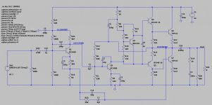
Hello .Just playing with this old amplifier schematic in LT Spice and gives a low frequency peaking.How dangerous is this in real life?It has to do with the different R-Cs and low corners that are close to each other but how to find the and eliminate it?
Attachments

Last edited:
You have several LF coupling issues here. C1 couples two stages and provides one phase shift at LF while there is also a capacitor coupled feedback.
It would be a good training exercise for you to try and write the LF coupling/decoupling responses and find out, but generally speaking amplifiers today don't put feedback around an ac coupled internal link.
C7 reduces the feedback at low frequencies which could boost the gain, and that leaves the effects of C5 and C2 to limit LF gain. Also the input capacitor will contribute.
Wha tthe peak will do is to enhance any LF signal like rumble or D.C. power instability and cause loudspeakers to "flap" with increased distortion. It may be better to simply change the NPN input to PNP and directly couple it to Q2. Obviously the biasing would all need to be changed but that makes it more or less a standard circuit.
The value of C1 should be much smaller, by a factor of ten or so. Try about 0.22uF instead.
Last edited:
This kind of topology was popular in the Ge era, pre-seventies, probably because it had some reminiscences of tube amplifiers, and precisely because of the bass-boost.
It is of course unacceptable now, and the simulation includes the mitigating effect of the input and output caps. The naked amplifier is even worse.
It would probably be possible to make the peaking gentler by tweaking C1, C2, C5, C7 values to arrive at a pole-splitting compromise, without altering the base topology
The design is over 50 years old. We accepted that back then. We can accept that today, if we wish. Keeps the woofer cone busy.
Some phono preamps had MUCH worse subsonic bumps. Signal generators did not go below 20cps and simulation was hardly born yet.
You can re-invent this wheel but better plans are widely available. (And most are simpler.)
Some phono preamps had MUCH worse subsonic bumps. Signal generators did not go below 20cps and simulation was hardly born yet.
You can re-invent this wheel but better plans are widely available. (And most are simpler.)