Bluetooth Audio Receiver - any recommendations?

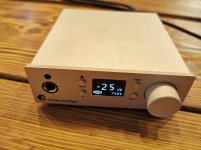
I'm looking for a Bluetooth receiver unit - to use in applications like putting Bluetooth into old car stereos, or adding BT to home audio devices etc.

Online searches give suggestions, but if even if they are just a year or two old, sometimes either the items are no longer available or there's new and better models.

The features I'd like would be ...
* When pairing, only beeps are audible, not a voice at full volume announcing the pairing!
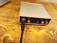
* Preferably aux input so the Bluetooth can be interchangeable with an aux in, particularly useful for car stereos.
* Power input can be anything but 5v-12v DC as they mostly are.
* Just line-level out, no further amplification.
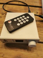
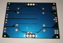
* Preferably just circuit boards, rather than units in plastic casings.

I don't wish to buy every cheap Chinese unit on the market in a process of elimination, but I've had two so far and rejected them...

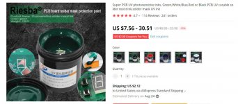
Bluetooth Audio Receiver Board Bluetooth 5.0 MP3 Lossless Decoder Module | eBay
(sometimes called XY-BT-Mini or JH-BT) It works OK but has the annoying, loud spoken pairing messages. If only there was a way to change that these might be ok.

DollaTek Upgraded version of Bluetooth 4.2 audio MP3: Amazon.co.uk: Electronics
(Dollatek, or LQSC or Drok brand - seems to be all the same).
It pairs quickly, only has beeps to pair, and it has aux inputs, but the sound quality is terrible - thin, no bottom, plus there's a raspy whistle which seems to begin and end when an audio track is played. (Power supply was 9v battery to avoid power supply noise).
(This unit gets good reviews on Amazon, making me wonder if I just got a dud. If that was the case, is there any fixes which can be made to mine before I send it back?)

Any recommendations for cheap Bluetooth receivers?

Or on the other hand - suggestions of ones to avoid? At least it will help us know what not to waste time and small amounts of money on.

Thanks
Jim

How do variable mu audio compressors compress without introducing distortion?

Hi folks,

Was thinking about this, with no particular circuit in mind. Some audio compressors, use variable mu tubes. We all kmow the principal: As the grid voltage lowers with respect to the cathode, the grid contours get closer together, so the gain changes.

The characteristics looks a lot like the cold-clipper bias used in guitar amps to create intentional harmonic distortion! Now this would sound terrible in a studio compressor. So this cannot be the full story!? There must be a way to get the compression effect without distortion. Or no? Any idea what else is going on is this type of audio circuit?

3D printed SSE parts and another DH SSE

A few years back a forum member posited a query about a MOSFET-less TSE, and over the course of a lengthy thread, an SSE with directly heated final amplifier tubes emerged.

Tubelab SE: Removing MOSFETs?

The experimental DH SSE that emerged ( 2A3 finals ) has worked without any component failures or other issue for the last three years. The TSE and TSE II have nothing to fear from that amp, but it is a nice and very simple beginner DH amp nonetheless.

The chassis - a 12 x 10 inch piece of scrap plywood, plucked from a trash pile ( literally ), bugs me. Likewise, the exposed voltage, while acceptable at the time, due to changing circumstances is now unacceptable.

Another thing that has bugged me was the level of damage caused to the SSE PCB to make a DH amp. It's terrific for experimenting, but it's not for the faint hearted builder. Also as part of this thread, will be an attempt to build a DH SSE using readily available, directly heated, tubes that does not damage the PCB in any way - all modifications will be fully reversible.

I hate metal chassis working, even though it is the best choice for an amplifier, imo. I have zero woodworking skills, so that's out. Recent acquisition of some 3D printers has caused me to consider whether or not a 3D printed chassis can successfully support a tube power amplifier, specifically, the experimental DHT SSE and unmodified SSE amps.

Printing a breadboard or complete chassis may or may not work. It may be that the heavy power supply will need to be separated from the main chassis. It may be as simple as a plastic printed plate emulating the breadboard piece of wood, or maybe mounted on an inverted metal chassis, or a nice wood base. Heat from the tubes and power transformer may be a deal breaker. It may be a complete waste of time, plastic and bandwidth.

To start somewhere, I made a template of the SSE PC board, and printed it out, and it looks pretty good, but I don't have a board here at the lake to match it up with and make sure all the holes correspond satisfactorily. It may need some minor tweaking. I made a quick 10 x 12 x 2 inch model chassis ( the same size as my Hammond chassis / cage based child resistant SSE ), with the SSE template embedded, just to get an estimate of the economics. At my current filament price for high temp PLA, the 12 x 10 x 2 chassis would be about ten bucks at 50% infill, and will decline some as more holes are added for transformers, meters, etc. So, it looks like the economics are favorable.

I am still in the middle of another project that has turned out to be more difficult / time consuming than I had anticipated; there will a lot of trial and error involved here; and I can only print the big parts at my office where I have the big printer, so this project will play out over some length of time just like its predecessor, but if you are looking for a reason to build another SSE ( and who isn't? ) this could be that reason.

EDIT 11/27/2020

I have made the pcb template public on TinkerCad, so it can be downloaded and copied for any purpose. It is tagged under "tubelab" and "w5jag" so a search for either tag will bring it up.

This way anyone can download it, ungroup the parts in TinkerCad, and tweak it as needed for their personal printer, or modify it for any other use. I will do likewise with any other models made for this project.

I did this because while it fit to the pcb like a glove when printed on my big 500mm Creality, it was off a bit when printed on my box of parts printer. I suspect the calibration on the factory built Creality is accurate, whereas my box of parts printer is not at this time. So this way folks can tweak it as needed for their printer.

Attachments

Output transformers a cheap alternative?

For valve power supplies I have been using back to back transformers. Drop mains down to 6vac for heaters then transform it back up to a round 200VAC using transformer backwards. This seems to have worked well.

I was wondering if I can do a similar thing with output transformers. Output transformers are very expensive and sometimes hard to find. The ratio needed from primary to secondary is about 1000:1. So output of valve amp goes into a 240VAC:12VAc transformer then into a another 240VAC:12VAC transformer.

Would this work ?

Subwoofer Plate Amplifier Base Plate supplier?

So I was thinking of putting together a DIY class D amplifier for a subwoofer with a few features that I imagine aren't typically found in your average amp. Probably something in the 1 to 2 kW range.

My primary interest is in the electronics/processing capabilities of the unit and not the plate portion. I was wondering if anyone knew of a supplier for buying just a standard base plate or would I be better off just buying the $99 dollar plate amp from PE and scrapping their amp section?

If nobody sells these standard chassis, does anyone know of a company that would do prototyping for such a chassis at a reasonable price in the 10 to 20 unit volume?

Thanks for any advice,

Jason

Oscilloscope recommendations for valve audio circuits

Hi,

I'm designing some valve audio circuits and trying to fix/debug broken amplifiers. It's time to upgrade from my crappy multimeter!

For audio, scopes can be slow, like 20MHz is enough, but I would like high bit depth to have a good dynamic range. But it seems not possible at a reasonable price. I want an FFT feature, or at least the ability to get the waveform out into a computer for processing.

I heard cheaper scopes tend to be killed by ESD or by voltages in amps, so something robust would be better.

Any recommendations?

Cannot adjust bias current, Hafler 220

When doing some searching for hum on a PC19 board, power arced to the frame (I think from the B- side of the board, to the heat sink, then to the chassis, but it happend too fast to know if it was + or - for sure). There was a noticeable spark, but no smoke or obvious burned wires or components. The rail fuses on the channel I was working on blew, but both channels were affected. It seems that current went through the frame to the other channel. I think I smelled burned plastic, but it was very, very faint if at all.

After the spark, I could not adjust the bias current at all on either channel. It is fixed at 20.3mA, with the amp switch on or off. Rail voltage is 69. This is a bit high, but I put in a higher capacity toroidal capacitor, and I think the voltage is what it was before the spark.

I replaced the PC19 boards with a spare set, but this made no difference. Voltage is zero at R21 and R30.

It seems like the problem would be behind the PC19 board, so
I checked the wires behind the PC19 board for continuity (okay), and the resistors (R38 to R41) check out also. Although they tested okay, I also replaced C24 and C30. This raised the bias current to about 54mA, but I still could not adjust it, and after turning the amp off and on, it is back to steady 20mA. Perhaps these caps drew a little current for a while.

The toroidal tranformer seems fine, but I put the original transformer and bridge rectifier back in anyway, but this did not help.

My meter does not have enough voltage (1.5) to test the MOSFET's, which I think need 5. I could build a tester (like Pass's on his web site. Frank Van Alstine told me that he's never heard of all MOSFETS breaking all at once, and they rarely fail anyway.

Even so, as a last resort, I bought matched NOS MOSFET's (2SK134, 2SJ49), and put them in. The steady 20mA bias current remains. Now I doubt that any of the FETS are broken.

The star ground is okay, and is continuous with the ground on the heat sink.

I am stumped. I may build a MOSFET tester anyway, to be sure, but I think I am missing something obvious. I looked at another thread that dealt with low bias current (20mA) on a Hafler 200, but that problem was solved by replacing FET's on the board. As mentioned above, I replaced the boards with ones I know worked before.

Could there be a problem with the MOSFET sockets? These look pretty simple and rugged to me, with not much to go wrong.

Stuff to trade for nicer bookshelf speakers or speaker components

I am looking TO TRADE for a nice set of bookshelf speakers or speaker driver pairs (SEAS, Scanspeak). Condition of cabs not too critical , I am a woodworker. In fact, I may just want the drivers only to make it easier depending of course on condition. I have for trade or sale:

Technics SL-10 TT w/ P28 cart currently installed and working plus an EPC-310mc that needs retip as an extra ($300)
JBL Smith horns- need paint ($200)
B&K Reference 30 (like new cosmetically)- for parts w/ extra NOS faceplate (stuck in "please wait")- ($125)
speaker selector switch-($25)
Optimus Pro X-5 all metal satellite speakers-($25)
Transparent toslink cable- 12 ft- ($75)


Would be great to work with these items above if someone could use anything there. And prices do not include shipping. If something is priced out of whack, PM me with a reasonable offer. And I will pack the heck out of anything I trade/ sell- membrane backed sheet foam and securely double boxed separated by sheet foam. You will be very happy with packing. I guarantee it. I will only ship insured through Fedex unless you want me to use a different service.


I am looking for specifically:

*SEAS 6-7" woofers, coaxials, tweeters (newer)
*Scanspeak woofers and tweeters
*ProAc Tablettes
*Focal- JM Reynaud speakers, Eggs, etc.
*Signet- SL 260 or drivers from them, SL 280, SL256, SL 16- I am even interested in SL 260 orphans.
*Evett and Shaw Elan
*Totem
*Dynaudio speakers, tweeters and woofers
*RBH MC-6C, TS-10AN, TS-12AN
*Target and Lovan speaker stands- 20-28" high


Thanks for looking.. I will trade multiple items too.

Behringer EP4000 gone pop x2

Hi all, first post here! I have 2 x Behringer EP4000's driving 8x18" subs in an infinite baffle system for my home cinema.

I have had them up in the attic for 4 years now, they are remotely powered when the receiver is powered up.

Recently i noticed i wasn't getting the usual 'ompf' that i used to, and ventured up there to see what's going on. Both amp's integrated breakers had tripped. On switching them, they would both buzz and trip off again.

So, I've pulled one out of the loft and via a process of elimination discovered the channel one is causing the tripping of the breakers.

I pulled that board out for closer inspection and discovered T16, a 50N06 had blown its top.

I have found a schematic online but don't pretend to know exactly what i am looking at here. I can replace the 50N06, but is there anything else it would be worth testing and upgrading while in there? I will pull the other amp out of the attic, but i suspect that as both went at the same time, it will have the same issue.

Thanks for any advice🙂

Steve

Attachments

  • IMG_7048.jpg
    IMG_7048.jpg
    952.8 KB · Views: 2,350
  • IMG_7051.jpg
    IMG_7051.jpg
    638.8 KB · Views: 601

  • Poll Poll
JFET matching Jig

2Oz copper & dedicated jumper

  • 2oZ copper

    Votes: 15 100.0%
  • Dedicated jumper clip in kit

    Votes: 9 60.0%

JFET matching Jig- Only 1 Oz available

Here is a simple circuit for matching SMD and through hole JFEts. Works for both N and P types and SOT23 and small through hole type.
Can measure
ID
IDSS
Vp
Details here
SMD jfet test jig
No KITS , only PCB

Here is the link to mouser parts list for V2 version (matches dual jfets such as 2SJ109)

https://www.mouser.com/ProjectManager/ProjectDetail.aspx?AccessID=86c42aff55

Manual for assembly and use with parts list here for older version. Principle is the same for v2.
JFET matching Jig

2-10M1A just a package designation for original Toshiba dual JFETS. And no such socket is available anywhere that I am aware of.
So what I did was get these two parts (Its in the mouser list linked at the first page)
90147-1104
90147-1103 and solder them at the 4 pin and 3 pin positions and use a drop of superglue between them. Don't forget to hold them together tight while glue is curing, with a clamp.
The dual jfets will slide in without any difficulty.
DON'T FORGET ,if you don't hold them together they may get pushed to the side by glue while curing.
However ,You do not need the socket or dual switch for board to work with non dual jfets.

FS: Audyn True Copper Max caps

Hi all,

For sale are my 2.2uf ATCM caps.

There is about 75 hours of use on them and have been used at around 165vdc for all of that time, so in absolutely no way have they been stressed as they are rated for 630v!

Possibly the best cap of all time.

Will post anywhere in the UK for the asking price, ROW will be at the cost of postage.

These were £256 new.

I'll sell them for £200, no offers.
20210811_145214.jpg20210811_145221.jpg

OT: Phantom Acoustics Active Acoustic Control

Hi all,

so so, papa is probably developing everything ... found this in the german ebXX classifieds. :wiz:

Also Phantom Acoustics Shadow active low-frequency acoustic control

@Nelson,
can you say more about this product and your patent (US4899387A)? :wave:
Could be an interesting new project ...

Attachments

  • $_59.JPG
    $_59.JPG
    103.6 KB · Views: 288
  • US4899387-drawings-page-2.jpg
    US4899387-drawings-page-2.jpg
    321.7 KB · Views: 264
  • US4899387-drawings-page-3.jpg
    US4899387-drawings-page-3.jpg
    301.8 KB · Views: 263

And now I have a horn problem

Edit: I should have written "flare".

So, my march toward improving my 2 way PA cabinets continues. My crossovers are in California waiting for a friend to bring them to the UK. My first Eminence PSD:2002 driver arrived and I unloaded the cabinets. I unscrewed the Motorola clone piezo from the flare, picked up the Eminence and ... it wont fit; close but no cigar. I don't know if its some kind of Chinese semi metric thread, but short of re-threading they wont go together.

That leaves me having to bin the flare and find something new. Flare terminology is outside my experience. I assume a 1" throat has a 1 3/8" thread? Dispersion: a 60X90 is the dispersion angle yes? For PA use I shouldn't imagine that I would want much height. For Horizontal is 90° about right?

As wide as possible? I might need to make a complete new front to get the hole right. Current Flare measures 390 X130mm (15 X 5").
Its all unraveling 🙁

TDL Nucleus 2 Mid/Bass driver Replacement

Hello all, I need some advice and hoping someone can help.

I have a pair of TDL Nucleus 2 speakers. A dodgy amp has blown one of the mid/bass drivers, original is SKO130 at 4 ohms.

Willys hi-fi had some Peerless M13NH also 4 ohms as replacements, but they are all gone.

Now the question I have is, if I find a replacement at 8 ohms can I use them, will there be any problem with current cross overs?

Many thanks Bryn

Question about the LX521's crossover

The LX521's crossover involves a 1st order crossover between the lower and upper midrange.

How is dipole EQ applied to the dipole rolloff of the upper midrange when the passive crossover is 'in the way'?
(Dipole rolloff for the upper midrange starts sooner than the lower midrange due to the narrowing of the baffle between upper and lower midrange.)

Does SL just arbitrarily EQ the resultant dip flat instead of precisely applying a 6Db/octave EQ to the upper midrange?

I read SL's commentary on his web page but dont seem to find the explanation.

Trying to do a similar design using a 'filler driver'.

Looking for info on RCL Electronic CV523 module

I recently bought this RCL Electronic CV523 module. The tubes that came with it are EF86, ECC81 and E283CC.

I can't find any information on it, except for this: pandcampkit

This is what I could find about RCL Electronic:
- RCL SPRING REVERB- RARE | mark's Gear Outlet | Reverb
- Echoschall – Bibliothek: Studio Magazin 1983-06 | Heft 62 - Seite 32-33

Perhaps someone knows what they are exactly? And even has a schematic of it? Else I have to draw up the schematic myself (which would bring some diy in the picture).

Thanks.

Addition: There are two transformers on it (not included what could be inside the metal box on the left and not included the relais), so probably one is for microphone input and the other for line out.

Attachments

  • 1.jpg
    1.jpg
    178.4 KB · Views: 90
  • 2.jpg
    2.jpg
    177 KB · Views: 84
  • 3.jpg
    3.jpg
    92.1 KB · Views: 71

Bridge 6xLM1876 12 channel amp into 6 channels?

Hi folks

I've acquired a multi-room amp that uses six LM1876 chips to produce 12 channels.

I want to use it as a 6 channel amp so I'd like to bridge the output of each LM1876 into a single mono channel.

I've desoldered the speaker pin connectors with the aim of soldering on wires that I will then run to screw terminals I shall install in the back of the chassis, but I'm unsure as to how to connect those wires in order to bridge the outputs.

I'm also not clear on how to connect the inputs - each channel has the R and L inputs clearly marked, but I'm not sure how to connect them to a single input channel - connect R and L together so they are both receiving the same input signal?

Attachments

  • DSC00750.jpg
    DSC00750.jpg
    273.3 KB · Views: 156
  • DSC00757.jpg
    DSC00757.jpg
    428.5 KB · Views: 142
  • DSC00757b.jpg
    DSC00757b.jpg
    201.8 KB · Views: 167
  • DSC00758.jpg
    DSC00758.jpg
    430.1 KB · Views: 132
  • DSC00760.jpg
    DSC00760.jpg
    511.1 KB · Views: 136
  • DSC00760b.jpg
    DSC00760b.jpg
    459.3 KB · Views: 83
  • DSC00761.jpg
    DSC00761.jpg
    497.1 KB · Views: 68
  • DSC00761c.jpg
    DSC00761c.jpg
    103.3 KB · Views: 68
  • LM1876 Bridged 2.png
    LM1876 Bridged 2.png
    182.2 KB · Views: 75
  • LM1876 Bridged.png
    LM1876 Bridged.png
    55.7 KB · Views: 121

A few words about myself

Hello everyone 🙂
My name is Keri, the vacuum tube witch, geek and activist 🙂

I've been doing electronic stuff since late 1990s / early 2000s. Most of it is audio-related, especially building, repairing and modding guitar and hi-fi tube amps, or some occassional stompbox. Other than that, it's general electronics, electrical engineering, systems/network administration, mechanics and typography / metal type casting. I did some fun digital projects in my life, like my recent vacuum tube tester, some home automation, computer controlling a Monotype composition caster (hot-metal typesetting machine used in the printing industry for a good part of the 20th century) or connecting multiple GoPro Hero3 cameras for synchronized shooting, and I began getting into DCC controlled model railways recently, but my core interest is audio and I can consider myself a semi-professional tech. I'm an autodidact, no formal training, I learned all I know from books, the web and especially from doing stuff myself, getting zapped a few times in my life and gaining superpowers from it 😀. I used to volunteer at a students' radio station where I was doing electronics/maintenance stuff and tried my hand at live sound engineering, but that passed and I normally haven't touched the mixing console other than doing a gig or two later in my life, when I worked for the Book Art Museum in Lodz.

I've got a little electronics lab at home, had it since 2000s when I was in high school. Equipment came and went (I still have a lot of pity about having to sell the OS102 - a Polish copy of some Tektronix tube oscilloscope), skills and knowledge developed. I'm running on a super tight budget, with some vintage test equipment (meters, generators, scopes) and a small stock of vacuum tubes and other parts.
My design and engineering philosophy is hugely inspired by 1950s and 60s professional electronics design. Point-to-point wiring, hand-laced cable harnesses, 19" rack-mount enclosures and all that. I hardly ever make a PCB, and when I do, it's almost always modern stuff.

Personally I'm a 35 year old trans woman on the autism spectrum, living and running her little operation in Gdańsk, Poland. Trying to get by repairing stuff for people as I'm a natural born technical problem solver (interpersonal problems are a completely different story, though I'm seemingly getting better) and taking on challenges is so much fun to me.

Old speaker terminals better than new?

I've read that silver connectors are best and even better than modern "gold plated" ones,
I'm wondering if the original speaker terminals in my Quad 303, 405, 606 are pure silver and if I should prefer keeping them over "upgrading" to something like this:

10PCS gold plated binding post banana socket connector 4mm banana plug amplifier speaker terminals Non magnetic banana connector|Connectors| - AliExpress

Daft 500w valve amp - advice.

For a while now I've a box of 813's under the bed, and as one does I've thought about using them to build a gurt big amp. The power supply is mostly sorted out,however the big obstacle here is the OPT's.

Before I can wind them or get them wound I need to know the Z pri etc. The 813 datasheet has specs for AF amp & modulator, class AB1, which gives a Z pri of 19k. This sort of amp isn't really going to be hifi at that power OP, speakers would have to be big subs or PA gear, but to get decent specs up to 100w say,what Z pri are we looking at?

Any advice thoughts are welcome. I am aware of the lethal voltages at play here and it being a bit of a daft idea, it's got to be done though,just for the craic.

TFL, Andy.

Inexpensive planar tweeter comparison

Digging through some of my planar tweeter stock, I noticed striking similarities between the larger Hi-Vi / Swan, Dayton and Silver Flute tweeters.

To my ears, all these tweeeters sounded similar in character and had noticeable production tolerances from one batch to the next.

The ones that always stood out as more competent were the HiVi RT2C-A and RT2H-A based on their sound signature. Both are around 94 dB @ 2.83 V

The more narrow bodied Dayton Audio PT2C-8 appears to have the same drive assembly and element, but it doesn't sound quite as clean up top as the two larger HiVi units. This was also a suitably proportioned tweeter for building line sources, although the examples of these I have auditioned didn't sound that great. I remember reading the PT2C-8 being compared to the Silver Flute YAG20 planar, which got a bad review by Zaph as supposedly the worst tweeter he has ever tested. From my experiences I could list several low cost hard and soft dome tweeters that sound far worse than the PT2C-8.

Then there's the new Dayton PHT1-6 which is a horn loaded version of the PT2C-8, but with a major difference. The PHT1-6 is a 6 Ohm driver with a heat sink mounted on its back and the PT2C-8 is 8 Ohms without a heatsink. I can't see how the heatsink will increase powerhandling. Maybe its just a gimmic... who knows. Without any measurements taken, evaluating by ear with music and pink noise, the PHT1-6 sounds much clearer and also louder even when reducing the drive voltage to comoensate for the 6 to 8 Ohm imoedance difference. They claim the PHT1-6 to have 105 dB @ 2.83 V which isn't that far off when comparing a 1 inch compression driver/horn combo. There are audible harmonics when trying to drive it below 1.5 kHz and I wouldn't want to run this tweeter below 2.5 kHz @ 12 dB. It is advertised as being a pro driver, so we'll see if my expectations are on point...

Plate-to-Line And Input Transformers and the Miller Effect with High-u Triodes

I will be using a triode-connected D3A as the input stage for my LCR phono preamp.

The input stage will utilize a MC-SUT, with a secondary winding impedance of around 70,000 ohms. The primary winding will match a 250 ohm input impedance.

My question here relates to the -3dB response of the input stage due to the series resistance/impedance presented to the high-u D3A by the MC-SUT, and it's effect in conjunction with the Miller capacitance of the tube. This of course can be easily determined once the Miller Effect input capacitance of the D3A has been determined, which I have done.

I want to determine the -3dB response of this stage, when driven by this particular MC-SUT. This can be easily calculated by the standard equation 1/6.28 (RC). However, I need to know how to determine the value of R (or Z) presented to the grid of the D3A input stage, when using an input transformer.

Is the series impedance presented to the input stage grid the impedance of the secondary of the MC-SUT? Or does the issue of reflected impedance come into play here, that being the source impedance of the MC cartridge?

Pictures -- Why Not attach Them ??

RANT ON ----

Now we have the new improved forum, Why, oh, Why do members persist in posting photos using Photobucket or some other hosting site ??

Do they not realise that the attachments will disappear in time ?
Do they not care ?
Is it just laziness ?


A jpeg of almost 1Mb is BIG !!!!
and more to the point, remains for ever on the forum.

So please. if you are posting photos and you MUST use a web-hosting site, at least post a small jpeg so we can see what the heck you were on about when we visit the thread in a years time !!!


Ban PHOTOBUCKET !!


/RANT OFF

Portable Bluetooth Speaker Build

I have been contemplating building a portable bluetooth speaker for a few years now, but between cost, complexity and parts availability, I had never pulled the trigger.... until just recently.

I had used the Dayton PS95-8 drivers in a couple micro bookshelf speakers for friends over the years and had great success. They have (in my mind) a good cost to quality ratio... they sound quite decent, are very forgiving with cabinet choices and need nothing but a notch filter to tame the spike between ~10-15k to be a solid performer. These were the foundation for this project.

I didn't want to just rely on a couple 3.5" full ranger's for this build so I started digging into my options for some bass duty. I found this when digging around and it looked perfect for the job... so I ordered a TB W5-1138SMF (the ferrite version, not the neo), and 2x Dayton ND140PR.

Next, I needed a power source and and an amplifier. I wanted as much power on hand as possible so I ordered the Dayton LBB-5 battery board to hold 5x 26650 batteries. For amplification I settled on this little guy as it seemed like a simple all-in-one solution. I also ordered the Dayton Lbb-5EB so I could have charging in and out available in a convenient location... plus, who doesn't want the ability to charge their phone from their speaker???

I used Google SketchUp to see how I could squeeze all these components into the smallest space I could here... Once I had the details all worked out I needed wood. A gorgeous piece of paduk caught my eye, and I already had some black bamboo from a previous project kicking around that would work nicely as a front baffle.

After some woodworking, I tested to see if the passive radiators would fit with the ferrite magnet version of the TB 1138... boy, my sketchup model was bang on; only a couple mm per side of clearance!

With the successful test of driver clearances, it was time to do some more woodworking and start to test fit the battery board, extension board and amp board, as well as some LED's and n' whatnot. This is went surprisingly well given how tight everything has to be to fit.

Sadly, i forgot to take a photo of the tidy finished version of the electronics section, so all i have is this really rough looking V1.0 to ensure fitment of everything.

Finally, fully assembled and ready for testing - sitting beside my MTM build from a couple winters ago.

Okay, the important part: sound. First though, a note. I am attempting to compare apples to apples here; does it sound like $10k super speakers? nope, not even close. Does it sound incredible for a portable bluetooth speaker? Absolutely. They have very clean mid range, detailed highs and WOW bass. In my 16x26 main room, they pump out thick, room-filling bass, even at decently loud volumes. I haven't yet pulled out any measuring tools, but I would estimate an f3 of ~45hz (though much lower is very much present) with the slightly flatter tune on the PR's I have done. Integration with the PS95's is good, and the 2.1 amp board has enough control to blend things nicely. Battery power has been amazing so far too; I have had it running at moderately high volumes for over 5 hrs and gone through roughly 25-35% power. My only complaint is that the LBB-5EB (expansion board) LED never turns off. My plan is to incorporate a toggle inline with the wiring harness so I can manually disable it when it's not in use.

All-in-all I am very happy with the final product. It just needs a carry handle of some sort and I can drag this behemoth (it's not light) around!

PS: This isn't an attempt to get praise for building something; there just seems to be a lot of interest on the internet for projects like this but not a ton of good info, so I figured (despite some reluctance) to make a post. I am happy to answer any questions if someone is interested in a similar project.

Attachments

  • IMG_3174.jpg
    IMG_3174.jpg
    565.5 KB · Views: 139
  • IMG_3097.jpg
    IMG_3097.jpg
    1,005.8 KB · Views: 107
  • IMG_3107.jpg
    IMG_3107.jpg
    719.8 KB · Views: 116
  • IMG_3139.jpg
    IMG_3139.jpg
    991.6 KB · Views: 99
  • IMG_3161.jpg
    IMG_3161.jpg
    454.2 KB · Views: 130
  • IMG_3157.jpg
    IMG_3157.jpg
    917.8 KB · Views: 136
  • IMG_3164 2.jpg
    IMG_3164 2.jpg
    1.1 MB · Views: 118
  • Like
Reactions: ZMathers

Speaker Layout for Public Address at a Community Fair

Hi All,

I have six horn speakers that I am planning to use to provide public address for a community fair on a rectangular field that is roughly 200m x 100m.

I don't do this very often (I'm just helping out with some PA gear my father left me, I'm not a professional) and I was wondering if anyone has a view on which of these two arrangements might be better:

(A) a central arrangement where six speakers are at roughly 60 degrees to each other and the sound radiates out from the centre;
(B) three speakers in each of two corners on one side of the field, directed inwards to cover the field.

(Please see attachment that contains an approximate diagram of these arrangements.)

Part of this clearly depends on where various stalls and things are, but setting that aside for a moment I am leaning towards (B) rather than (A), with the public address based in the middle of the long side in the between the speaker groups in the corners. I think this is likely to be less 'deafening' for everyone near the centre of the field, although it will need a bit more cable run.

I'd value any opinions, recommendations or thoughts on additional considerations, please?

Many thanks,

Andy.

Attachments

  • Layout Options.jpg
    Layout Options.jpg
    17.8 KB · Views: 134

Any suggestions for a diy rival to a Bose SoundLink mini?

Guys and Gals, I've always wanted to make something that is compact and packs a bit of a punch. I've tried searching a few things over the past year and haven't seen much, but certain I'm just looking for the wrong thing. Has anyone successfully made something in a full range that could rival a Bose SoundLink mini or equivalent mass produced BT speaker?

Although still quite large I had a go using Dayton Audio ND65's and was a little disappointed when they started to distort with half volume, yet folks seem to be rocking 40mm drivers and a PR off AliExpress and getting those lower notes? I only have YouTube to go off, but with no T/S specs I wonder how one sizes anything correctly? Maybe I was being too adventurous trying to go down to 65hz, but it modelled well in WiniSD

I really want to build something small so any suggestions?

vu meter

hello

i bought for test this vu meter see atachement

and this driver board see atachement

it works but the pointer ies rather dull just following the musik signal,,,,

i want it more like on yamahas p2200

so pointer moving fast to the right and is slowed down on the way back (left)

someone knows different driver board?

thanx and regards to everyone here rron

Attachments

  • vu1.PNG
    vu1.PNG
    437.1 KB · Views: 190
  • vu.PNG
    vu.PNG
    367.5 KB · Views: 192

What Horn is currently available to replace the SEOS 12 with a bolt on flange?

I have been digging through the threads trying to find what currently available horn will work with a 12" woofer. There are thousands of pages here on the topic. This will be an "Econowave copy" I believe what I am looking for is a CD 90 x 40 horn with a 2 bolt mount for the CD. (I like what PI speakers and SEOS have developed) What is the go to horn right now? Will the Dayton H6512 with an adaptor work?

I know the answer is already on the forum, I am just having trouble searching it out!

TIA,

Duane

Harman Kardon AVR 335 receiver repair

Hi, several years ago I bought a new Harman Kardon AVR 335 receiver. I listened to it for about a month and bought something else. I put it back in the box and it stays like that for several years. Recently I decided to put it in the garage but something is wrong with it. It powers up, everything on the display works fine but no sound on the speakers. I will open it in the next few days to check it. But wanted to ask for some advice as to what it could be, the fault is obviously caused by staying in the box for several years. Thank you

chinese UV solder mask drying

Hi, about this solder mask (attached)
Most of the videos showing application use transparent plastic film as a layer, between the solder mask and the printed layout.
But there are problems after UV curing - taking the plastic film off could cause the solder mask to be removed from the PCB.
I have similar problems with dry photoresist film - sometimes it peels of the pcb.

Is there any agent, than can cause the applied on pcb solder mask to become dry?
So that it is stuck to the pcb and exposed without the extra transparent film.

Attachments

  • solder mask.JPG
    solder mask.JPG
    91.4 KB · Views: 222

linkup ethernet cable

Hello,
I need to make some ethernet cables from a bulk cable

LINKUP - Cat8 Ethernet Cable S/FTP 22AWG Etched Solid Cable-2000MHz (2GHz) up to 40Gbps- Future 5th-Gen Ethernet LAN Network 40G Structure Wires-Yellow-50 Meter Bulk (Termination Required)
Brand: LINKUP

I across this one on Amazon but it is 50 meters or 165 feet. I will only need around 10,6 meters or 35 feet.

I there anyone in Europe who want to join me ordering OR anyone who has 35 feet or a bit more '' in stock ''
Greetings, eduard

Loesch Adagio DAC analog filter

Hi all,

Sorry if this has been already discussed but I could not find much info on the implementation of the analog filter of Adagio:


1) What are the RLC values of the double T filter: 70mH+1nF+?R, 70mH+47k ??
2) Has anyone implemented it? What chokes have you used? What core type? What DCR?
3) The gain seems huge or I'm missing something? 1:15 transformer then E182CC SRPP gives amplification >300 Or the filter chokes have a big DCR?
4) How exactly is the filter tuned including the parasitic components? How does one retune it? I'd be interested in a better transformer.

Thank you,
Jarek

New Cherry NDFL amp

Hi Folks, first post from a relative newbie and former lurker, so here goes...hope you can read the circuit....its long, bear with me.

I am actually a switch mode PSU designer who moved into analogue and mixed signal semiconductor sales... it pays more!My background is Linear Tech, Burr Brown, Unitrode, TI but I have always had a hobby of audio dating back to when I was 11 years old...a long time ago now. Now I am selling motors..more on that another day.

I first experimented with nested feedback by putting a 400W MOSFET amp inside the feedback loop of a OPA627. Fixes the DC drift just great...and actually works quite well. Why...the sales director wanted 'more bass'. I reckon he just needed to clean out his ears...

But it got me interested in nested feedback, and I read the Cherry papers. And wished I could remember more of the stuff I learned at college.....that's what sales does to you.

The original objective was, using the Cherry paper (with his permission for hobbist use incidentally), duplicate his results and make a judgement as to the subjective audio quality.
As time went on the project slowly mutated into a 'make it as best you can' then apply NDFL feedback.

The input stage was elaborated to a CFP type in an attempt to achieve best linearity with the minimum additional complication.

The Rush stage was retained but with the inclusion of R21 to limit the maximum stage gain to something sensible...I am a pom after all so good to have a UK circuit in a Monash Univ. paper!

The VAS transistor was chosen as a BF469, to preserve as much HF performance as possible, rather than use a MJE. I appreciate other much better (and easier to obtain) transistors exist now.

Likewise the current source for the VAS stage was elaborated to a cascode. Later this was found very handy as it was modified to dethump the amp at turn on and diodes were added to the supply rails to prevent positive feedback thumping the amp at turn off.

The output stage was eleaborated into a CFP driver with common emitter output. The object here was to present minimal loading to the VAS, maxmimised voltage swing and allow multiple pairs of output devices to be driven, if a high power version was required.

The prototype used Rod Elliots P03A as the driver...thanks Rod!

The output and driver transistors are the newish On Semi MJE15035 and 36 with MJL4XXX outputs.

The thermal tracking is split into two, one Vbe multiplier tracking the driver drift, the other tracking only the output temperature mounted smack on the face of the output transistor. This appears to work very well.

In the Cherry paper he suggests that including the output stage withn the CDOM loop is acceptable, it is certainly not using this more elaborate and possibly slower output stage, hence the position of C9 is conventional except that it is now part of a nested system.

The choice of transistors is not totally trivial in this design BTW, quite a lot of work was undertaken to prove the CFP stages were stable.

What does it sound like...well I think pretty good, no transistor 'edge' and very good resolution. It has powerful
but uncoloured bass too.

BTW some years ago I built the Self amps and verified his results..yes he's right THD+N circa <0.0005 in a 80KHz BW (APS1 noise floor stuff) but the amps sound diabolical on music, still have the pcbs if anyone interested. For anyone trying this, wiring up the amps and the test equipment is more critical than the choice of transistors...back to the Cherry amp..

Spice analysis (thanks LTC, great free tool!) shows the overall loop gain to be very similar to an amplifier with 2 pole CDOM feedback, very high gain at low frequency, followed by a 2 pole roll off reducing to a single pole at unity. But this is achieved in a more controlled fashion, so I suspect, but cannot prove, lower overall distortion.

What do you guys out there in DIY land think? 😀 or :bawling:

And thanks to Hugh Dean for tea and sympathy...sympathy for trying to build this thing in the first place!

Attachments

  • cherry_1_1.jpg
    cherry_1_1.jpg
    98.8 KB · Views: 3,594

Measurements of Turntables/Record Players - in which Test Magazines to find

There are probably a wide range of audio/hifi magazines around the world (in many languages).

here some examples:
StereoNET Expands into NZ with Purchase of AudioEnz | StereoNET Australia - Hi Fi & Home Cinema News
SoundStage! Hi-Fi | SoundStageHiFi.com - SoundStageHiFi.com Equipment Reviews
MJ Magazine (formerly Musen to Jikken) - Yearly Index from 1924 - 2009 wanted
Stereo Sound ONLINE
Home Page | Hi-Fi Choice
https://www.whathifi.com
https://www.theabsolutesound.com
also there are online magazines, e. g.
https://www.audiophil-online.com
https://www.lowbeats.de

Which of these magazines also carry out measurements with regard to speed accuracy, SNR etc. ?

Obviously there aren't many of them. Even stereophile - go to
https://www.stereophile.com/content/lack-phono-measurements-stereophile
perform this only in individual cases like this very rare examples:
https://www.stereophile.com/content/linn-sondek-lp12-turntable-lingo-power-supply-measurements
https://www.stereophile.com/content/linn-lp-playing-system-measurements

It seems to be, that such measurements are usual at the u.s. magazine AUDIO - go to
https://static1.squarespace.com/sta...41acad/1489563683682/Plattenspieler+Audio.pdf

Any few measurements are to find the web:
https://www.audioasylum.com/message...ents-of-harmonic-distortion-from-my-turntable
https://www.woodsongaudio.com/service/thorens-td124-main-spindle-bearing-rebuild
https://stereo-magazine.com/review/sme-model-12-review

In old magazines like those in post #38-41 under
Overview from world's best historical and currently available electr/audio Magazines
so as in the magazine "l Audiophile" - go to
http://6bm8.lab.free.fr/Documentations/Revues/Audiophile/1977-1988/01/PHONO/PHONO.html
and
http://6bm8.lab.free.fr/Documentations/Revues/Audiophile/1977-1988/42/VERDIER/VERDIER.html
there are more measurement results to find.
Last both links are to find under
http://6bm8.lab.free.fr/Documentations/Revues/Audiophile/index-1977-1988.html

Thanks for advices to magazines with measurement results in their test reviews.

Studio Projects C1 Condenser Mic fading on and off at random

Hi Everybody,

I have been asked to take a look at a Studio Projects C1 condenser microphone which is basically not working correctly. After plugging it in, there is no life. Then it starts to hum and come to life where if you tap the mic it is working. When I speak into it, it gives good quality vocal then it cuts out and dies again. It will remain of for a while and then come back on itself.
I have checked the components on the pcb. All seem good. I’ve went over all the solder joints. All are good.
Has anyone here come across the likes of this before? Could it be the capsule?
I attach a few pics.
I am going to replace the J305 Incase it is not working correctly. I have removed it from the pcb to test it. It seems ok but I might replace it anyway. Other than that I’m in need of a little help.

Kind Regards,
Paul

Attachments

  • E9A7A7A4-9937-448C-B382-AD720A672005.jpg
    E9A7A7A4-9937-448C-B382-AD720A672005.jpg
    1,007.4 KB · Views: 221
  • 1F2989D9-5842-49CC-B191-FAC055C8C1A7.jpg
    1F2989D9-5842-49CC-B191-FAC055C8C1A7.jpg
    669.7 KB · Views: 187
  • FC841C6A-EFF7-4C2A-BAE7-125CCD1D3B2C.jpg
    FC841C6A-EFF7-4C2A-BAE7-125CCD1D3B2C.jpg
    783.3 KB · Views: 188

Need To Choose Hashimoto Choke

I'll be building a Sunvalley 300B amp (their SV-S1616-D with Hashimoto output transformers). This is a new amp that will be released early September of 2021.

I'm going to build my own chassis and can make the width larger so I can then mount a choke on the exterior of the top plate along with the other transformers. The kit has a small choke mounted inside the amp. I'll be using a Hashimoto choke instead of the small choke that comes with the kit and now need to choose which Hashimoto choke. I found a schematic that shows this amp's circuit (attached in link below) and the only info for the choke value used is 4H.

I also own a Triode Labs EVO21 300B amp and found that they use the Hashimoto C-10-200W. That choke has an inductance value of 10H/2.5H.

The choke that I'm also considering for replacement of the kit's choke is the C-16-150W. That has an inductance of 16H/4H. The DC resistance is lower for the Triode choke and I'm trying to pick the best one for this Sunvalley circuit. I don't have the amp yet so can't measure the choke in their kit. However, the Hashimoto choke will probably be a better choice.

Would you choose the Hashimoto C-10-200W the same as Triode uses or the C-16-150W?

Here are the specs:

C-10-200W
Inductance: 10H / 2.5H
Rated DC Current: 200mA / 400mA
Max. DC Current: 250mA / 500mA
DC Resistance 140 / 35 Ohms

C-16-150W
Inductance: 16H / 4H
Rated DC Current: 150mA / 300mA
Max. DC Current: 180mA / 360mA
DC Resistance 200 / 50 Ohms

Which one would you pick?

Thanks for any help,
Richard

Here's the link to the schematic of this amp:

Sunvalley SV-S1616-D 300B Schematic

Input Capacitance of a Triode-Connected D3A

I have the Telefunken data sheet for the D3A.

It does define the input capacitance for triode-connection.

However, being the data sheet is largely written in German, and I can only read English, I am having difficulty in obtaining the following information from the data sheet for the D3A:

Cathode to Grid Capacitance, Triode-Connection

Grid to Plate/Anode Capacitance, Triode-Connection


I need this information so I can calculate the Miller capacitance for a triode-connected D3A.

Can anyone help?

Thanks in advance!

Hello from VT

My name is Lawrence and I live the village of Williston VT. I've recently taken on a diy project where I'm going to try to restore an old GE solid state stereo console (a533g) from around 1969. I thought I knew a lot about stereo equipment, but I've been humbled by this ordeal and have come to know I don't know jack.

I will be leaning on you all heavily over the next several months and hopefully be able to share with you my experiences.

Hope you're all staying safe and well.

Regards,
Lawrence of Vermont

Please help. Bassbreaker 18/30 - NO SOUND!

Hi everyone, complete noob to message boards, so I hope this is okay. I have a Fender Bassbreaker 18/30 combo amp that recently stopped working. I played it for a gig one night and the next day, no sound. I get a little bit of noise when I plug a cord in and touch the end, but nothing with an instrument plugged in. I checked the inline fuse with a multimeter and it seems fine, I inspected the tubes visually and nothing pops out at me. All of the tubes glow orange when powered up, the preamp tubes only a little. I'm hoping someone can give me some idea as to what my issue could be. Thanks

SRC4392 + ESP32

Hi All,

I am working on a DSP based on ADAU1466 + SRC4392, controlled by an ESP32 through SPI interface.

My programming skills are not so great, so i where wondering if anyone have a sketch they would be willing to share with me?

Currently i have tried this code which does not seem to do the trick;
Code:
#include <Arduino.h>
#include "PCF8575.h"
#include "SPI.h"

unsigned char audioSRCCom(unsigned char address, unsigned char data, bool read = false);
void audioSRCWrite(unsigned char address, unsigned char data);

unsigned char errorCode;

#define SPI_SRC   4
#define SPI_ADAU  5

#define AUDIO_SRC_R14_INTMASK	0xF4	// CRC, parity, validity, bip encoding, and dir unlock unmasked
#define AUDIO_SRC_R18_INTMODE	0xAA	// interrupt mode to level change
#define AUDIO_SRC_R19_INTMODE	0xAA

PCF8575 exp1(0x21);
PCF8575 rexp(0x22);

const SPISettings settingsA(1000000, MSBFIRST, SPI_MODE3); // Store SPI transaction information to settingsA

uint8_t audioSRCCom(unsigned char address, unsigned char data, bool read) {
  uint8_t Response = 0x00; // Set response to 0
	digitalWrite(SPI_SRC, LOW);
  SPI.beginTransaction(settingsA);
  SPI.transfer(address);
  SPI.transfer(0);
  SPI.transfer(data);
  SPI.endTransaction(); 
  digitalWrite(SPI_SRC, HIGH);
  if (!read) return Response; // End if only write session
  delay(1);
  digitalWrite(SPI_SRC, LOW);
  SPI.beginTransaction(settingsA);
  Response = SPI.transfer(0xFF);
  SPI.endTransaction(); 
  digitalWrite(SPI_SRC, HIGH);
  return Response;
}

void src_statuses () {
  Serial.print("SRC Interupt Status: ");
  Serial.println(audioSRCCom(0x02, 0x01, true));
  Serial.print("SRC Ready Status: ");
  Serial.println(audioSRCCom(0x0A, 0x10, true));
  Serial.print("SRC Ratio Status: ");
  Serial.println(audioSRCCom(0x0A, 0x20, true));
}

void initiate_src4392 () {
  src_statuses();
  audioSRCCom(0x7f, 0x00); // Initial write to page register, selecting page 0
  audioSRCCom(0x01, 0x80); // Software reset
  audioSRCCom(0x03, 0x31); // Port A format I2S, slave mode, src->porta
  audioSRCCom(0x04, 0x01); // Port A clock to MCLK/256 (48k)
  audioSRCCom(0x05, 0x41); // Port B format I2S, slave mode, mute output (port is not used)
  audioSRCCom(0x06, 0x01); // Port B clock to MCLK/256 (48k)
  audioSRCCom(0x08, 0x31); // Bypass Mux RX1, AESMUX BYMUX, LDMUX BPMUX, Enable AES and TX
  audioSRCCom(0x0D, 0x08); // DIR reference clock = MCLK
  audioSRCCom(0x0E, 0x08); // Automatic DIR-mute for loss of lock
  audioSRCCom(0x0F, 0x12); // Registers 0F, 10 and 11; PLL1 configuration. Values from datasheet: P=1, J=8, D=0
  audioSRCCom(0x10, 0); // Registers 0F, 10 and 11; PLL1 configuration. Values from datasheet: P=1, J=8, D=0
  audioSRCCom(0x11, 0); // Registers 0F, 10 and 11; PLL1 configuration. Values from datasheet: P=1, J=8, D=0
  audioSRCCom(0x16, 0xF4); // CRC, parity, validity, bip encoding, and dir unlock unmasked
  audioSRCCom(0x18, 0xAA);	// interrupt mode to level change
  audioSRCCom(0x19, 0xAA);	// interrupt mode to level change
  audioSRCCom(0x2d, 0x42); // Port B as input, MCLK as Ref, Mute Disabled, Volume tracking leftch.
  audioSRCCom(0x30, 0x07); // Set left channel volume -3.5dB
  audioSRCCom(0x31, 0x07); // Set right channel volume -3.5dB
  audioSRCCom(0x01, 0x3f); // Activates the chip, remove soft RST, Enable all.
  delay(10);
  src_statuses();
}

void setup() {
  delay(1000);              // 1 second startup delay
  Serial.begin(9600);    // Initialize the USB serial port for debug
  pinMode(SPI_SRC, OUTPUT); // src4392 CS pin
  pinMode(SPI_ADAU, OUTPUT); // adau1466 CS pin
  digitalWrite(SPI_SRC, HIGH); // Pull SRC4392 CS pin HIGH
  digitalWrite(SPI_ADAU, HIGH); // Pull ADAU1466 CS pin HIGH
  exp1.pinMode(P5, OUTPUT); // ADAU1466 Reset pin
  exp1.pinMode(P6, OUTPUT); // SRC4392 Reset pin - H/W Linked to ADAU1466 Reset, if ADAU1466 RST is low, SRC4392 will be low for atleast 300ms after ADAU1466 turns high
  exp1.begin();
  exp1.digitalWrite(P5, HIGH);
  exp1.digitalWrite(P6, HIGH);
  delay(10);
  SPI.begin();
}

void loop() {
  initiate_src4392();
  delay(5000);
}

Serial response from the sketch is:
SRC Interupt Status: 0
SRC Ready Status: 0
SRC Ratio Status: 0
SRC Interupt Status: 0
SRC Ready Status: 0
SRC Ratio Status: 0

Physically checked that hardware rst pin is 3.3v, and i am can program ADAU1466 through same spi interface

Schematic for the SRC chip:
Screenshot by Lightshot

Onkyo NR609 amp board

Hi all.

This is the board from a Onkyo NR609 AV receiver, complete with what IO assume is the preamp board, and I also have the original power transformer, as well as the small AC in board.

I was wondering, is there a way to switch on this unit and use it as a test amplifier or 7 channel power amp? I know it does not have the best sound quality, just thought it a waste to chuck it.


IMG-20200419-163129-resized-20200419-043153726.jpg


IMG-20200419-162644-resized-20200419-043004873.jpg


IMG-20200419-162626-resized-20200419-043004602.jpg


IMG-20200419-162835-resized-20200419-043005162.jpg


All else fails, I will be using the transformer for my APEX build, can always strip the main board and use the heatsinks and other bits.


I would however, appreciate some help in trying to get this to work, if its possible.

Regards
Cedric

ADP7118

Very simple question.

On page 16 of the datasheet it is explained how to keep the noise of externally configured regulators low.

The theory makes sense. Reduce the gain of the circuit down to unity at high frequencies so as to not amplify the broadband noise by the DC circuit gain.

What I am not understanding is how AD arrive at a DC gain of 10, for the configuration shown, using the 5V, fixed, regulator.

The datasheet explains that all the fixed voltage devices work at a gain of unity. So to get the 5V to output 10V it needs to be configured for a gain of 2. Which is what you'd expect given the feedback resistor values with both being 100k.

What am I missing?

How much polyfill to get rid of internal standing waves in a 2.16lt sealed box?

Can some please calculate the weight of polyfill required to get rid of internal standing waves of a 2.16lt sealed enclosure. Or is there a chart recommending the amount of polyfill in weight for enclosures of different sizes.

Box internal dimensions
Height:214mm Width:82mm Depth:132mm

1st mode standing wave wavelengths
Height Width Depth
801 Hz 2.09 KHz 1.30 KHz

PS: Since the box has been downsized from 11.5lt to 2.16lt, not sweating of the effect on Qtc.

HP 6263A

I picked this HP PS up at a hamfest awhile back for 10USD. It has no output. The raw DC is there. I can't find the manual for it. Electrotanya has the "B" model manual. Can anyone direct me to the "A" manual? Or do you know it they're close enough to use the "B" manual I have. A recap, new cord and cleaning of the controls are mandatory I know. Someone has also added an extra rheostat to the front panel. I'd like to attempt to get it working before I scrap it it. Thanks!

Attachments

  • thumbnail_image_50417665.jpg
    thumbnail_image_50417665.jpg
    311.6 KB · Views: 83

Testing / Verification of Gedlee Abbey Kit?

I'm currently building a pair of Gedlee Abbeys from a kit which was purchased by someone else some time ago. I've assembled the cabinets and I'm about to do the crossovers and final assembly.

I was wondering if anyone had any recommendations for measuring these speakers after completion, just to make sure I haven't done anything egregiously wrong. I have arta and a measurement mic, but it would be helpful if someone could recommend the axis, measurement distance and expected response.

Alternately, I could do an impedance sweep of the final system, but I can't seem to find an impedance graph of this speaker.

I understand Dr. Geddes is retired so I'd like to avoid bothering him directly; curious if any other Abbey builders have done any measurements.

Very much looking forward to hearing these speakers!

Electrically quiet isolated DC-DC convertor

I have a portable boombox built with a Raspberry Pi and IQaudio DAC . This runs from a 12V SLA with the Rpi powered via a Murata NDY1205C isolated DC-DC convertor . I am experiencing issues with 5V noise , which manifests at random as quiet whistling and crackles . No issues running from a separate 5V power bar or external PSU . The NDY device is connected as per the datasheet with low-Z 100uF bypass capacitors on input and output and cables are as short as possible . Minimum current for the device is 150mA , I measure 165mA drawn by the Rpi/DAC combination . Maybe I'm expecting too much from the NDY in terms of noise , but has anyone else used this device or similar DC-DC convertors and obtained decent noise performance without adding additional LC filters ?

Most frustrating , my scope is on the blink . First time in years I've needed to poke around in equipment 🙁

cheers

316a

TU-8600s Another Successful Build

Just finished the build. Was able to source all resister values in .5w Takman units. Except the 2w and 3w resistors. It was not easy. I heard Takman will no longer be producing them? Used a quad, matched within 1%, Vcap set. Of course, silver solder everywhere. Also, did the headphone output resister mod posted by bhk1004. Thanks for that.

First power on with no issues. All test points tested good for expected values. Except one, TP9. Should be 175v as TP10 was, but was 167.7. Could see one of the 12ua7 tubes was glowing a lot more on the bottom than the other. I know tube brightness is not a way to judge, but to me, it looks pretty obvious this one is pulling more current than the right one, causing the voltage drop. The voltage drop followed the tube when I swapped them with each other. This was supposed to be a matched pair, which usually means also balanced. Working to get another set from the ebay seller.

WD 300B's are the new reissue units they are making now.

So, far very pleased with what I am hearing. Speakers are 90dB 8Ω so no problems running them at my usual listening levels. 50 hours of burn in so far. We will see if anything changes when I hit 100 and 200.

The WD 300B's have a very pleasing glow to them once the lights go down.

Looking hard at the upcoming Sunvalley P1616D for next build project.

Attachments

  • Main Board finished 1.jpg
    Main Board finished 1.jpg
    264.1 KB · Views: 381
  • Testing Board 1.jpg
    Testing Board 1.jpg
    319.8 KB · Views: 373
  • 12ua7 current draw 1.jpg
    12ua7 current draw 1.jpg
    958.5 KB · Views: 376
  • Night light 1.jpg
    Night light 1.jpg
    671.2 KB · Views: 378

Trimming Veneer around Tweeter

Hello,

New member, and in the process of my first speaker kit build (building my own enclosures). My question is around veneering, specifically around the tweeter recess. Experimenting on a test board, I cut the outer recess circle and the inner through-hole for the tweeter and woofer, then veneered the board. Routing out the through-hole is no problem for either. But for the tweeter, the depth of the recess (3 mm) is less than the height of the bearing on my flush trim router bit, so I can't use that to trim the veneer.

Should I route the smaller hole after I veneer (I prefer routing the hole early when there is less at stake build-wise), or is there some tool/trick to trimming the veneer around a shallow recess?

Thanks

Trying to mellow out Klipsch KG 4.5 tractrix horn

I bought a pair of Klipsch KG4.5 speakers in good shape. I kind of like them (my first horn speakers), but they have a harshness in the treble that I'm trying to tame.

So far I've applied a layer of duct seal (a la Planet10) to both the tweeter horn and the woofer frame, which has helped gain clarity and smoothness. But the tweeter still has a little sizzle to the top end that bothers me.

A lot of people have said to replace the crossover capacitors, but they look like reasonable quality metallized Mylar film. How bad can those possibly be?

Here's the crossover schematic:

Kilpsch_kg-45_crossover.jpg


I was experimenting with putting a resistor across the + and - terminals of the tweeter. When I put a 50 ohm 10W wirewound there, the highs definitely get smoother and less brash, but maybe too 'dead.' When I put 100 ohm 10W it smooths the highs just a little tiny bit.

Here's what I've done to it:

Kilpsch_kg-45_crossover_MODIFIED_HF.png


Right now I'm listening with the 100 ohm there, and I think I want to try something like 82 ohms (split the difference between 50 and 100 ohms).

My question is -- Am I doing something incredibly stupid and wrong? I mean in general terms. I don't have the actual driver specs, so I understand that the crossover can't be properly analyzed from just the schematic. But in general terms, is putting a resistor across the tweeter likely to cause a problem?

Am I just attenuating the tweeter output by setting up a simple voltage divider between the series resettable fuse (that "polyswitch" thingie, which has 0.5 ohm internal resistance) and the parallel resistor?

Thanks...

The best 8" mid bass

Working on a new project of 3way speaker with follow configuration high sensitive Twitter SB Satori TW29BNWG-4 and 8" Mid-bass (over 92- 93 dB) to driven by tube amp,.. and 2 x 8" Subs VISATON GF200 driven by extra active D Class amp.

I cannot make a decision for mid-bass. In narrow selection are now:
- VISATON 200B
- Acoustic Elegance TD8M
- Beyma GH40 8 OH

Any suggestions or your experience are very welcome.

Pro-ject Pre Box Digital S2

Lightly used, everything works, comes with the remote. Condition, "as new"

Perfect mate with Tidal MQA.

Price 240€

Shipping possible to anywhere, ask for shipping quote

Attachments

  • IMG_20210813_194240.jpg
    IMG_20210813_194240.jpg
    472.3 KB · Views: 111
  • IMG_20210813_194748.jpg
    IMG_20210813_194748.jpg
    646.4 KB · Views: 113
  • IMG_20210813_194805.jpg
    IMG_20210813_194805.jpg
    656.3 KB · Views: 106
  • IMG_20210813_195123.jpg
    IMG_20210813_195123.jpg
    397.8 KB · Views: 109

LuDEF kit packages

Presenting thread here: LuDEF


Schematic and pcb screenshot post #1 , plenty of pictures after .

Tips and Tricks thread - will open, sooner or later

Reading entire thread is advisable , same as inquiring any technical question there : Be sure that you are aware of all things electrical and mechanical !


Pcbs are made for UMS , mounting directly to heatsink


Do not hurry - read , think , ask and only when you feel that you want it and can make it , proceed ...... advice which I'm finding applicable on practically anything .

For anything else , write either here , send PM or directly to >zenmodiyaudio@gmail.com<

Prices are mostly dictated with small scale nature of operation (as always is case) and time/work involved in matching and soldering little buggers.

For ordering , contact me at above written e-mail addy .


edit on 27.11.2021. : pcbs changed for easier LU mounting; see (see post #620)


Kit options :

Option 1.
- LCH pcb ,
- RCH pcb ,
- all smd buffer JFets (Toshiba 2SK2145BL) presoldered ,
- smd precision CCS chips presoldered
- all smd caps and resistors presoldered ,
- 4pcs of 1uF MKC caps (for important bypass positions) enclosed.
-pair of small Daughter boards for LU (see post #620)
-mica for BD cascodes heatsink mount

Full price , including Paypal fee and P&P for registered shipping all around the Globe - 135E

Option 2.
- LCH pcb ,
- RCH pcb ,
- all smd buffer JFets (Toshiba 2SK2145BL) presoldered ,
- smd precision CCS chips presoldered
- all smd caps and resistors presoldered ,
- 4pcs of 1uF MKC caps (for important bypass positions) enclosed.
-all multiturn trimpots
-output mosfets , 2 pairs , IRFP240 & IRFP9140
-IRF510 & BD 139 - source follower/level shifter duty
-cascode bjts
-optocouplers
-all electrolytic caps (all Panasonics ,except Elna Silmic II for one signal route position)
-one-pin sockets for special resistor positions
-all (MF 600mW) resistors
-T0220 heatsinks - 6pcs
-pair of small Daughter boards for LU (see post #620)
-mica for BD cascodes heatsink mount
-etc.

to recapitulate - everything what goes on pcbs , excluding signal xformers and pcb/mosfet mounting screws/nuts/washers ; also excluding LU1014**

Full price , including Paypal fee and P&P for registered shipping all around the Globe - 185E


**LU1014 - in this moment I have quantity for, say, 35 kits; ask for them - tested and Ids matched, if you don't have them already; matched pair ( you'll get them soldered to Al boards) is 8E


If I have everything in drawers in moment of order , can ship in a week time;
If I don't have any of normal parts in drawer , shipping could be delayed up to 3 days;
If I don't have pcbs in drawer , shipping could be delayed up to 2 weeks;
If I don't have most critical part for getting in my neck of wood - CCS precision chips , shipping could be delayed up to 3 weeks.
All in all - you all know that ZM is slow, but inevitable

Handy Addendum (in short : HA!):

-Cap Bank pcbs - set of 2pcs; dual rail, CRC (pads, if you want differential CLC), snap-in up to 35mm Dia, resistor and pads for LED, position for 10mm NTC connecting Audio GND to chassis;
-NTC pcb/ FW style Soft Start - set of 2pcs; each having place for 2 independent NTCs;depending of arrangement of primaries of Donuts you're using. you'll need either one pcb for two Donuts, or one pcb per Donut

HA! set is 25E more

see pics for HA!; lazy to search do I have photo of NTC pcb, but who cares

Attachments

  • PSU pcb bottom.jpg
    PSU pcb bottom.jpg
    58.1 KB · Views: 1,415
  • PSU pcb top.jpg
    PSU pcb top.jpg
    86.1 KB · Views: 1,409
  • CB top eagle sshot.png
    CB top eagle sshot.png
    54 KB · Views: 1,402
  • CB bottom render.png
    CB bottom render.png
    88.7 KB · Views: 1,401
  • CB top render.png
    CB top render.png
    160.1 KB · Views: 1,384
  • eagle sshot.png
    eagle sshot.png
    17.4 KB · Views: 274
  • bottom render.png
    bottom render.png
    18.5 KB · Views: 246
  • top render.png
    top render.png
    38.4 KB · Views: 222
Projects by fanatics, for fanatics
Get answers and advice for everyone wanting to learn the art of audio.
Join the Community
507,815
Members
7,889,555
Messages

Filter

Forum Statistics

Threads
406,304
Messages
7,889,555
Members
507,815
Latest member
ezemattaldi