Onken for Audio Nirvana super 15 inch full range
- By MVH
- Full Range
- 15 Replies
Hello all,
First time posting, so I thought I’d take the opportunity to thank the community for all the info I’ve come across on this forum. I’m completely new to this and you guys have been a huge help up to now, but the more research I do, the more questions I have, so I’ve decided to jump down the rabbit hole and register as a member.
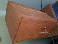
A friend of mine wants me to design a cabinet for a audio Nirvana Super 15 inch ferrite full range driver, and the enclosures that Audio Nirvana suggests are a one size fits all configuration of very basic bass reflex boxes, which makes me think there’s room for improvement.
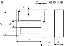
I found out that the cabinet I’d sketched out was called an Onken type enclosure, and that those had been developed by “mad scientists” (not my words) who wrote down a rudimentary chart for proportions, but no actual formula.
I’ve found a calculator online : mh-audio.nl/Calculators/Onken.html which lets you put in the parameters of your driver and the size and number of vents and that gives you the total volume of the box and the length of the vents. Perfect!
I’d read you could simulate these in Winisd as well, so I figured it would give me additional information and check the maths. And this is where my issues start.
I’ve modeled the data I got from the online Onken calculator and found out that the box was tuned to 44 Hz.
As I mentioned above, I am new to this, and there is a lot of information to digest, so I have a bunch of questions, most of which will seem very basic. I am a fast learner though so bear with me please, and thank you in advance for your patience.
- The driver is rated for a free air frequency of 31,7 Hz, which is the default value Winisd gave me when I started the project. I am guessing I should aim to tune the box by tweaking the vents to be as close to that value as possible, correct? What is the consequence of the 44 Hz tuning that the online calculator suggested?
- The driver has a test bench frequency response from 31 Hz to 16000 Hz. Does that mean that I should set the minimal frequency on my model at 31 Hz and assume anything that happens on my model below 31 Hz will have no impact because there wouldn’t be a signal?
- Should I aim to have F3 as close to 31 Hz as I can?
I understand these parameters are determined through box volume and vent volume, and I can fiddle with those until I find the best curve. This will also determine wind velocity which should not exceed 18 m/s.
Then I started looking at cone excursion. And this is when the real issues started. The driver is rated for a 50 watt RMS which is what I set my signal to. And at that rate, the curve only drops beneath the drivers Xmax (1 mm) after 140 Hz or so. I understand you can filter out the signal up to a determined frequency on your source, but 140 Hz seems ridiculous. I can also get the curve to drop if I lower the input power, but I have to drop it to 3 W to get it below the 1 mm line, and that’s ridiculous as well. I’ve noticed the dimensions of the box have an influence on the cone excursion, and the smaller the box, the lower the curve, but if I want to drop below the 1 mm line, the box gets so small that I’m better off not bothering with a box at all.
I’d like to avoid filtering the signal as much as possible. There must be a way of designing the box so that it doesn’t blow the driver up.
So what am I missing? Up to cone excursion, I could (almost) get my head around the various parameters. But at this point, my model makes it look like the driver is unusable, which I’m sure is not the case, so what’s going on?
Many thanks for your insights, I’ve only just started and I am already very confused and frustrated!
Max
First time posting, so I thought I’d take the opportunity to thank the community for all the info I’ve come across on this forum. I’m completely new to this and you guys have been a huge help up to now, but the more research I do, the more questions I have, so I’ve decided to jump down the rabbit hole and register as a member.
A friend of mine wants me to design a cabinet for a audio Nirvana Super 15 inch ferrite full range driver, and the enclosures that Audio Nirvana suggests are a one size fits all configuration of very basic bass reflex boxes, which makes me think there’s room for improvement.
I found out that the cabinet I’d sketched out was called an Onken type enclosure, and that those had been developed by “mad scientists” (not my words) who wrote down a rudimentary chart for proportions, but no actual formula.
I’ve found a calculator online : mh-audio.nl/Calculators/Onken.html which lets you put in the parameters of your driver and the size and number of vents and that gives you the total volume of the box and the length of the vents. Perfect!
I’d read you could simulate these in Winisd as well, so I figured it would give me additional information and check the maths. And this is where my issues start.
I’ve modeled the data I got from the online Onken calculator and found out that the box was tuned to 44 Hz.
As I mentioned above, I am new to this, and there is a lot of information to digest, so I have a bunch of questions, most of which will seem very basic. I am a fast learner though so bear with me please, and thank you in advance for your patience.
- The driver is rated for a free air frequency of 31,7 Hz, which is the default value Winisd gave me when I started the project. I am guessing I should aim to tune the box by tweaking the vents to be as close to that value as possible, correct? What is the consequence of the 44 Hz tuning that the online calculator suggested?
- The driver has a test bench frequency response from 31 Hz to 16000 Hz. Does that mean that I should set the minimal frequency on my model at 31 Hz and assume anything that happens on my model below 31 Hz will have no impact because there wouldn’t be a signal?
- Should I aim to have F3 as close to 31 Hz as I can?
I understand these parameters are determined through box volume and vent volume, and I can fiddle with those until I find the best curve. This will also determine wind velocity which should not exceed 18 m/s.
Then I started looking at cone excursion. And this is when the real issues started. The driver is rated for a 50 watt RMS which is what I set my signal to. And at that rate, the curve only drops beneath the drivers Xmax (1 mm) after 140 Hz or so. I understand you can filter out the signal up to a determined frequency on your source, but 140 Hz seems ridiculous. I can also get the curve to drop if I lower the input power, but I have to drop it to 3 W to get it below the 1 mm line, and that’s ridiculous as well. I’ve noticed the dimensions of the box have an influence on the cone excursion, and the smaller the box, the lower the curve, but if I want to drop below the 1 mm line, the box gets so small that I’m better off not bothering with a box at all.
I’d like to avoid filtering the signal as much as possible. There must be a way of designing the box so that it doesn’t blow the driver up.
So what am I missing? Up to cone excursion, I could (almost) get my head around the various parameters. But at this point, my model makes it look like the driver is unusable, which I’m sure is not the case, so what’s going on?
Many thanks for your insights, I’ve only just started and I am already very confused and frustrated!
Max