build small simple cheap full range speakers for my 2.1 system...

first time project, I want to expand my knowledge of carpentry , electronics and DIY in general.

SIMPLY PUT

I want to make a pair of VERY simple TINY speakers for my desk, I have a little 2.1 amp and a subwoofer below. I want it to be dirt-cheap so I wanna build with reclaimed wood, upcycling as there is so much waste wood in the streets around in London where I live.

Going for cheapness and simplicity I would like to opt for two single driver speakers and closed back. At that size I think that is about right.

Ideally they would be about 20-30watts each...

So two little cubes basically!

I have no idea where to start and I didnt want to trawl through tonnes of hard core technical stuff, I am not good with maths and stuff.. Just wanna keep it simple and practical.

I know that I need to choose some drivers then work out the dimensions of the speaker based on those..

So there is a formula I need for this right?

And maybe I wont need a cross over if its just a single full range driver in each of the speakers?

Thanks!!!

Current Dumping, Class A Performance With No Idle Current

I came across this blog. Current dumping for dummies? – CONNERLABS

The most well-known implementation of "Current Dumping" is Quad 405.

The "Current Dumping" topology claims to eliminate the crossover distortion with no idle current at output stage. Is that true? or just a marketing things?

Here is my little experiment.
sch.PNG

sim.PNG

It holds its claim pretty well. 0.002% THD@10KHz under +-20Vp-p.
The number is even better than an average Class B amp.😱

Hybrid Circlotron - DC offset, what have you used?

So my OTL HPA project backend has moved to a class A circlotron. Actually two - one for tube and one for a pair of helper BJTs. The design is based on using the tube output rather than tube input into the base of the SS output stage. The idea seems to work, at least on paper/LTSpice. It also seems to scale between 32ohm to 600ohm however I still need more experimentation. However before that - I need to tackle the DC offset.

Screenshot 2021-09-11 at 09.44.51.png
(ignore the spurious labelling of resistors)

Broskie has used a pair of cross linked LPF from in the input to the opposite phase to balance DC but I'm interested in alternatives and if the added complication of say active opamp makes a difference.

I suspect I'll need to use two - one for tube DC offset and one for SS offset with the risk of oscillations.

An Aleph 2 for $27K in ebay

So, someone has posted a pair of Aleph 2 on Ebay... I guess it "pains" him to even sell them because his must be special.

$27K.

Pass Aleph 2.0 pair of Monoblock stereo amplifiers | eBay

Now, I've been wanting a pair of such amps for years. They tend to go around 3500 to 4K... and I got quoted about 1200 ( shipping is $$$) from the factory to recap them.

I gave the guy an offer which is fair... specially as he really doesn't say what shape they are and has not even bothered to post pictures.

Surely, I hope not to hurt his ego... if he moves on my offer, fantastic.

And as my wife said: "Honey those are pretty ugly amps"... to which I replied: "Well, that's why the Maggies are such wide speakers, we can hide the amps right behind them:... ;-)

Low DCR Chokes: Will it improve transients/dynamics?

In talking with a friend, he suggests using low DCR chokes for the powers supply, on the order of < 10 ohms per choke.

I am currently using 10H/225mA/51 ohm chokes. In your experience, will changing chokes to a 5 ohm DCR result in better transients and dynamics compared to the 51 ohm chokes? I would use the same brand/specs, Monolith Magnetics but just lower the DCR to 5 ohms. I am trying to get a bit more snap / liveliness to the sound.

Thoughts?

Attachments

  • C3g-45B v13 7.28.21.png
    C3g-45B v13 7.28.21.png
    77.8 KB · Views: 1,019

Sonic Quality of L-pad attenuator for tweeter

I just want to conform from other members here that does Lpad attenuator affect sonic quality of tweeter. I tried a tweeter with 6db Lpad attenuator another without attenuator. but reduced the same db at amplifier to match the output at tweeters. what I felt was the tweeter without Lpad, Sound better crisp and clearer, and sound more natural.
Just want to know from you all here is , what difference I heard, makes sense or just my illusion. Also is some body can explain how series resister in attenuator makes the difference. resister in series of any driver affects the damping of driver. so how this affects tweeter?

Regds

FS: pairs of SEAS MCA15RCY and 22TAF/G drivers

FS: pairs of SEAS MCA15RCY and 22TAF/G drivers -SOLD-

selling pairs of SEAS drivers in good condition, only used for a short period of time in a non smoking area
2 pcs SEAS Prestige MCA15RCY - H1262-08 5.5" Coated Paper Midrange
2 pcs SEAS Prestige 22TAF/G - H1283 7/8'' Aluminum Dome Tweeter -SOLD

asking for half of the current price: 130 Euros plus shipping -now 80 Euros for the MCAs -reserved for Jim

all sold -thanks a lot!

Attachments

  • Seas2.JPG
    Seas2.JPG
    542.1 KB · Views: 320
  • Seas1.JPG
    Seas1.JPG
    707.2 KB · Views: 321

Valve rectification question

Gents,

I am trying to understand more about my 211 amp, and it has two 5u4GB rectifiers, and on the main transformer only 0 450v apparently no centre tap. ......I think...

Could it be a voltage doubler circuit maybe?

Is there a good way to see how the circuit works without a strip down, as a lot is out of sight.

Can I learn anything by taking some measurements from the 5u4 valve base etc.

211 is at ~1000v, so yeah I know it's dangerous poking around!

Just trying to learn things, no real reason other than initially trying to understand if my driver valves are diode or valve rectified.

Thanks,

Refreshing of Audiolab Pre-Amp

Apologies for the long winded post and I hope I posted this in the right section of the forum.
So this Audiolab 8000C has been my pre-amp for what must be +10 years now and is paired with a 8000P power amp, the latter being in mint condition and rather well looked after.
The pre on the other hand I got totally screwed when buying it, other than the age the thing was caked in heavy cigarette smoke and whilst it doesn't smell any more on the outside, the inside still smells and is coated in a thick layer of tar.
At that point I pretty much gave up and just ended up using it as is for god knows how long.

It's always had some issues i.e. scratchy pots with poor channel matching, faulty relay, susceptible to mains pops and a scratchy eq on/off button.

Now instead of buying something else and selling this (it's pretty worthless in it's current state no?) I thought it would be nice to get it back up to spec as it's not a bad pre but just needs some TLC.

Plan of action so far is as follows;

Replace all Electrolytic capacitors > Ordered ELNA Silmic II's and Nichicon LKG for the PSU mainly cos the solder tabs just make it easier and they're easily available at Mouser.

Replace Volume and Balance pots > Still Need to source

Replace Relay > Still Need To Source

Now I am not an expert and would love peoples suggestions/input on here, am I missing something etc.
The pre-amp obviously gets hot, those transistors with the heatsinks are very close to the caps etc.
Is it worth while replacing some of the polyester and polystyrene capacitors in the future too?

I am having difficulty sourcing suitable pots (Noble dual log 30k) and if anything will use a 50k pot albeit I still have difficulty sourcing something of that particular size and that is of quality.
Almost thought of using a ALPS RK-27 and just using jumper wires instead of mounting it to the PCB although size is probs an issue.

Switches.. One day haha One thing at a time at the moment.

FS : Fostex FE206En full range (pair)

Hi,

I'm selling a pair of Fostex FE206En in mint condition, approx. 50h of moderate use.
Shipping to Europe only.

Price 135€ for the pair.
Shipping is about 16€ to most European countries.

Attachments

  • 2021_0904_05240700.jpg
    2021_0904_05240700.jpg
    653.5 KB · Views: 233
  • 2021_0904_05242000.jpg
    2021_0904_05242000.jpg
    632.9 KB · Views: 223
  • 2021_0904_05243000.jpg
    2021_0904_05243000.jpg
    669.6 KB · Views: 218
  • 2021_0904_05243400.jpg
    2021_0904_05243400.jpg
    601.3 KB · Views: 214

Pre outs on Rotel to sub & full through Speakers???

Hi
Please correct me if I'm wrong but its my understanding I can connect my powered subwoofer to the pre out (not sub out) connection provided on the rear of a Rotel rx950ax receiver I'm looking at?

My question is, as it will be sending full range audio to my subwoofer amp through its pre out will the Rotel still then be able to play full range audio to my stereo speakers connected to it while at the same time sending full range to the subs through its pre out?
Regards
Tim

Rotel rx950ax rear pre outs
ad_1631145203708.jpg

T2500-1bdcp rockford help.

Hey guys I have a rockford t2500-1bdcp on the bench. The unit would power up then directly into protect. It had some blown output fets. I replaced the out put fets and the amplifier will turn on and play however it is drawing about 9 amps of current at 14.2 volts and one of the voltage regulators lm337t is getting hot and heating up the top left of the heat sync. Is this normal? I have not hooked it up to high current yet so I don't know how the amp acts under a load.

On The Back Burner 7 Watt 6EA7 PP Amp

This is a minor project I hope to nail before Spring 2021. The beginnings can be traced to the 6SN7 Push Pull Flea Amplifier Project by Lingwendil.
I got into the thread around Post #250, Fall of 2018. I was concerned that the proposed OPT would not properly load the PP 6SN7. Along the way I built a test chassis on a Betty Crocker cake tin, so I called it the Betty Crocker Special. The octal base pin out of the 6SN7 is the same as the 6BX7 & 6BL7. Tried those too.
Audio power is limited by the plate dissipation of the various tubes. I found in Class A & properly loaded OPT 3 watts could be got from a 6BX7 or 6BL7. The 6SN7 was good for about a watt at clipping. A friend donated a 5998 much higher powered twin triode for the tests. The 5998 managed 10 watts before clipping.
That group of twin triodes dissipate all the waste heat in one bulb. With a pair of 6EA7/6EM7s the waste heat can be shared by two bulbs. Simulations shew the possibility of a very compact, all triode amp capable of seven watts audio. With some wiring changes it would be possible to try that on the Betty Crocker amp chassis.
All externally powered by my home grown regulated PS. And I'll never build another amp, experimental or otherwise on a Betty Crocker tin. Not very convenient at all for making test measurements or circuit mods.

Attachments

  • 6EM7 Triode Amp 6EM7 Driver Common Bias D2.JPG
    6EM7 Triode Amp 6EM7 Driver Common Bias D2.JPG
    94.4 KB · Views: 605
  • 6SN7 Amp Betty Crocker Special.jpg
    6SN7 Amp Betty Crocker Special.jpg
    589.9 KB · Views: 632

Pure Player

Hello,

My belief is that most audio player software for Windows sound quite bad and this fact made me develop my own music player. It's free and you may download it from http://pure.truefreehost.com/pureplayer.zip (copy the url to your browser). Very simple, possibly full of bugs (early alpha version), but i believe it worths an audition... 🙂

Installation instructions:

.NET 4 framework required (for the GUI, the core is written in pure fast C)

Unzip pureplayer folder to c or any path without spaces.
Copy PurePlay Shortcut to Desktop and doubleclick it.
Press the "Readme" button 🙂

Looking forward for your reviews...

japanese speaker plans

I found a web site by a guy in japan with dozens of rear loaded and loudspeaker plans. They werent very large, maybe the biggest was 24"-30". It was a personal site. Computer crashed and lost the book mark. I dont know how I found it, but ive been searching and searching and nothing. Sorry dont have any other hints on whats on it. But the plan were pretty detailed. If anyone knows of the site or something similar can you please help me. Thank you.

Can I use a simple zener circuit to step down voltage for a turntable motor?

I have been given a broken JAM turntable which has a USB/digital output. The main board is basically kaputt but the motor, speed selector switch circuit and transformer/power-in circuit seem to be working ok so I want to convert it to just a simple analogue-only record player.

The motor is a 9V/12V pretty much like this one...New 13s/lot DC9~12V MOTOR with all switchs and wires 33 1/3, 45, 78RPM / turntable gramophone Plattenspieler|switch shell|motor figuremotor sliders - AliExpress
but the transformer and power board (bridge rectifier and filter cap) puts out 20VDC (previously it supplied the main board which then fed the motor with the required voltage (12VDC).

So basically I was thinking I could use a 12V zener diode to regulate the voltage to 12V to then supply the motor. Would a circuit like this work (call it 'circuit A')...?

https://www.electronics-tutorials.ws/diode/diode_7.html
(first pic on this page)


I was thinking if I get a 5w 12V zener then it would have a max current of around 410mA so the series resistor would have to be around 20ohms if Vin is 20V. Can it be that simple or am I missing something?

Another circuit I was looking at (call it 'circuit B')) was this one ... 12 Volt Regulated power supply circuit using zener diode ... which specifies motors in the description. I'd have to change some of the values here as this is 15V to 12V. Also I don't know what the transistor is for in this one...?

Any thoughts gratefully received...

Tom.

Ceramic phono carts. Are they so bad?

This summer there came to me the hare-brained idea of testing how good ceramic phono carts are - or are not. I know they are a relic of bygone days, but almost all the old consoles and record players I've restored used ceramic cartriges.

Ceramic carts are high output and need little to no EQ if the proper preamp is used. I have a nice new Sonotone (AKA Garrard) cart and a good old EV from my Clairtone. How well can they perform? I mounted the Sonotone on my AT tonearm with a new headshell and gave it a spin. The ceramic cart and headshell are so light that they float where the AT95E has 2.5g of tracking force. A dime on the headshell and a little balance adjustment got me to the 4.25g needed for the Sonotone.

It pugs right into my USB sound card and at 0.48V output, as more than enough level. It does suffer HF roll off, even tho the instrument input of the soundcard is supposed to me 1 Meg ohm. Below you will see two graphs, the shaggy one from RightMark shows the FR from a song on an old mono LP. White is the AT cart with RIAA, green is the ceramic straight in. The smoothed graph used the AT cart as reference and the plot is the FR of ceramic.

A more suitable preamp is the next step. That should fix the HF roll-off. Why all the bother? Because it's too damn hot to go out and work in the garage. This can be done in comfort. 😉

Attachments

  • MM vs CC music FR.png
    MM vs CC music FR.png
    13.9 KB · Views: 331
  • MM vs CC.png
    MM vs CC.png
    18.9 KB · Views: 318

Markaudio Studio Main Monitor build

Posting this in the Fullrange section instead of the Multi Way as this is mainly about Markaudio Drivers, hope thats ok.

Some while ago i build a 2-Way System using Markaudio Chr-120 and Chr-70 in an oversized sealed box (q around 0.4), first order crossover @470hz to compensate for baffle step response. Worked like a charm, i absolutely love the sound of these Speakers and also noticed that theyre actually better for mixing work than my and most other studio monitors I worked with and listened to, much more detailed, consistent soundfield and insane transient response.

To the point, this made me decide to build the main Monitors in my Studio myself, using Markaudio. Knowing from lurking and reading this forum some of you got extensive experience with these drivers, maybe you can help me with some questions still in my head.

1. Im planning on upgrading from the CHR to the MAOP drivers, so MAOP 11 + MAOP 7 - If I like the CHR sound is this a good idea? the consensus seemed to be the alpair are similar to the CHR in terms of overall character but just plain "upgrade".

2. The CHR-120 extends pretty low in a sealed box, MAOP 11 doesnt quite get there. For full range reproduction the Plan would be to go 3-way and add a bass driver for everything below the MAOP 11. Just feels kind of wrong to me in some ways, as i kind of dont want to **** up the minimal crossover design with an additional capacitor for the MAOP 11. Any of you had any experience with WAF designs, specifially the low pass filter for the sub?

Thanks!

FS: Klaudio KD-CLN-LP200 (Pump not working)

Removed: Klaudio KD-CLN-LP200 (Pump not working)

For sale is my non-functional Klaudio KD-CLN-LP200. The ultrasonic transducers were replaced by Klaudio in 2018 (can provide the service history). The drying cycle still works. However, the fill pump makes unhappy noises and causes the cleaning cycle not to engage. Physically, the unit is in immaculate condition with one exception - I'm missing a couple of the very small black screws that hold the rear body panel in place (but I'm sure if you know what to order, this is a $2.00 cosmetic fix). I have the original box and materials. Pictures (and video w/ audio) available upon request.

$500 + $100 for shipping within the continental US.

** Updated - Listing removed as unit has been returned to Klaudio for repair and updating. Unit may be relisted at a future date. **

Glassware ACF-2 cathode follower octal vs 9-pin questions

Hi all. I recently made a thread (albeit in the wrong section) asking for advice about what kind of line stage to build to go with my setup. Link here: Reccommendations for a preamp build based on my gain and impedance needssetups

The conclusion, with a lot of help from rongon, is that I need a near unity gain line stage, to go with my Quad 306 amp and Trichord Dino phono stage.

I am pretty set on getting one of the Glassware cathode follower kits, in particular the ACF-2. However, I am not sure whether to get the 9-pin or octal version. I have tried to find out the differences between them, but I am struggling to make sense of it. I have read a lot of conflicting opinions on the differences, from views such as that octal tubes offer more gain or octal tubes can offer a 'fuller' sound, but also views in the complete opposite of this.

I was more set on getting the 9-pin version, I think, but now that is out of stock. The octal version is still in stock, so I would like to get some opinion on what might suit me best if possible.

I have tried to contact John from Glassware with a few questions, but unfortunately, he has not got back to me. I have read elsewhere that his email inbox gets filled with spam so sometimes messages can be missed.

So, in short, I guess what I'm asking is what are the differences between these two kits?

Thanks in advance for any help!

Bias Marantz PM80 MkII

Hi,
I should calibrate the idling current of a Marantz PM80 MKII.
From manual service in class A should be 180 mV after 30 minutes, unfortunately, however, by turning the trimmer to the maximum I get about 140 mV on the tester.
I have clearly disconnected the load of the speakers and placed the volume at minimum and the sliders in the center position.
Would anyone know how to solve this problem?

thank you very much

opinions on best player for.... Pi music player

Hello,

So the twist on this question is... what's the best music player solution for a Pi 1 Model B with a Hifiberry Digi that is so old that Hifiberry seems to have erased all mentions of its existence (and how-to's)... I originally started by looking at Pi MusicBox, but see on this forum that Moode, Volumio and Squeezebox(?) among others seem popular.

I'm thinking that I have to use an old version of one of these that still supports the Pi 1B and 26-pin Hifiberry dac...

Thanks,

clueless

Polyswitch fuse for speaker protection

Hi,
I want to protect the 1" HF horn ( 40W/8 Ohms ) of my bass guitar cabinet with a Polyswitch resettable fuse. If I have calculated well the result for my HF is 2.23A. Do I have to match this result with the trip current of the Polyswitch? The RXEF- 110 shows a 2.2A trip current : Digi-Key - RXEF110-ND (Manufacturer - RXEF110) .Is it the right one or do I have to choose another value ?: http://dkc3.digikey.com/PDF/US2010/P2107.pdf
Many thanks,
Pascalou

The new EWA M40 power amp.

1) The Design Concept.
A power amplifier design that is value for money and able to defeat the competition at four times its price.

To use if possible the SECA designs we have used in the past with more power output but less material waste in large heatsinks and huge energy demands.

The design was if possible to have a fast rise and fall time to cope with the demands of frequency to frequency phase changes.

It must also be able to go in standby mode if the users forget to switch OFF but be able to restart at the pre-set level on the input, in this design it is set to the equivalent of 1W into 8Ω.

It must have balance and un-balance inputs.

With the digital noise on the main power lines it must be able to ignore them.

It has to be over engineered in the safety area, such as the main power inputs.

The protection device to protect speakers must be fool proof.

The whole design must be based on K.I.S.S.

2) The Specifications.
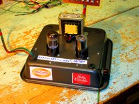
Dual Mono Design one channel only shown, right or left.

Power output 8Ω @ 45W RMS , 4Ω @ 90W RMS, 150W peak into 2Ω
Maximum Peak Current 1mS 50Amps
Maximum Short Circuit for fuse to blow 6A RMS
Maximum Allowed Heatsink Temperature 40C
Input Sensitivity Un Balance 0.7V RMS into 22KΩ
Input Sensitivity Balance 1V RMS into 600Ω
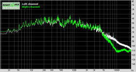
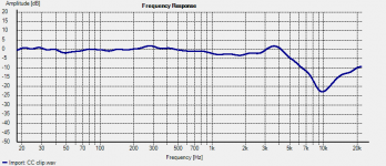
Full Power Bandwidth 0.0dB flat 10Hz – 100KHz
Full Power Bandwidth -1dB flat 1Hz – 130KHz
Phase Angle change 100Hz – 20KHz less than 1Deg
Driver SECA stage A Class Power 1W
Output Device each channel six with very high speed and matched HFE drivers.
DC offset less than 1mV (typically 100µV)


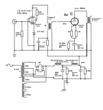
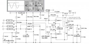
3) The Block Diagram
The power inlet socket is a PCB mounted IEC with a built in fuse holder.
The Earth connection is to the chassis of the M40.
Live and Return are connected to a isolating power switch which in turn is connected to the mother board FR4 PCB.
Please note the slots in the PCB near and around the mains input live and return this is to provide extra safety precautions and to exceed the current regulations required for consumer products. Then we connect to yet a non serviceable fuse holder and fuse, this is help prevent customer tampering and increase the safety margin.

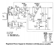
On the block diagram we show the POWER ON CIRCUIT this operates the start 16A relay with a Snubber Circuit around the relay contact to eliminate sparks and interference when operating. On Standby this circuit consumes less than 1W and in operation only 0.5W of the total power consumption. This block also has the two regulated power supplies for the RERERENCE VOLTS AND SENSE & TRIGGER CIRCUITS. These supply two ±V (V1+,V2+,OV1,OV2,REF V,V1-,V2-) and the 1.24V Reference voltages.
The TRIGGER POWER CONTROL section has two comparators which detect the input voltage on the power amp inputs and switch the POWER CIRCUIT on. The switch shown can be used to set the state the users needs, the QUICK ON SWITCH allows forced trigger to activate the power on timer of about 60 seconds this will turn off after this time if no signal is detected. The ON switch force the M40 to stay on in a continues state and the OFF switch keeps the amp deactivated and it will not trigger on.

The INRUSH LIMIT is to prevent the inrush current at peak mains from distressing the rectifiers and transformer. A note here all the main Bulk Capacitor are rated at a high ripple current, All other capacitors are designed to run in a temperature range of -40C to a max of 105C.
EMC & RFI FILTER’s 1&2 are rated at 4Amps each and are in common mode format.
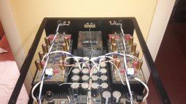
The main power transformer is rated at 250VA with 8 output windings of 24VAC. These outputs winding are configured by the FULL BRIDGE RECTIFIERS to be out of phase, this allow the B/H curve to be used more efficiently when both channel need to draw a large current thus reducing saturation of the transformer.
The transformer is dipped and vacuum impregnated with a high temperature potting compound to reduce noise and provide more electrical insulation and thermal conduction.
Also wound with a µMetal magnetic shield and a Electrostatic shield to reduce the RFI and EMC emissions.
So the total noise RFI and EMC radiated and detected by the M40 is very low an increasing the quality of the music you hear without the garbage generated by our digital world.

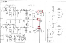
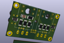
4) The Amplifier modules.
The two amplifier modules are the same circuits to each other but careful layout of tracks help to balance their performance. These two PCB fit either side of the mother board on heatsinks.
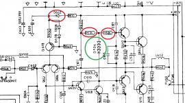
The input has a DC blocking polycarbonate capacitor and a input impedance of 22KΩ, fitted with a small capacitor which roles the input frequency to -3dB at 14MHz, this may seem high but it allow us to have very fast rise a fall times on edges.
The next stage is a Long Tailed Pair which drive the PNP SECA drive stage controlled with a constant current, This stage is running about 1W, the DC offset is also controlled in the first stages reducing the DC to as low as 1mV (normally less)
This is simple KISS design but with very selective components, the driver and front end circuit are provided power from two (±) hum busting regulated power supplies located on the mother board. Each module has its own separate set of power supplies and there for is dual mono.
The next stages are complimentary drives, these high frequency device are normally used in radio circuit and have a high HFE for power devices, theses six transistors are forced to current share in the base drive and collector to emitter current, the HFE are match to within 1% of each set of six.
There is also another high frequency device mounted to the main heatsinks this in conjunction with a NTC monitor the inside chassis temperature and the heatsinks temperature and control the bias current in the six output power complementary power devices.
The six power devices are also HFE matched to within 1% of each set. The total IQ (quiescent current) is 1A running the power stages longer into Class A then into A/B.
Each device is rated at 150W PD and at a max current of 25A so we have plenty of head room.
There is no frequency compensation in the negative feedback circuit so very little phase change occurs.

On the mother board we have put timed independent speaker anti plop circuits this may cause one channel to turn on before the other, They are provide power by the main PSU after the fuses so if a fuse goes the speaker are never connected to the amp, keeping the safe.

The Balance circuit is done with a instrument amplifier circuit design to convert balance to no balance, This and the Balance input is controlled by a pair of signal relays operated by a toggle switch. Both can have connection at once from different sources and the selected by this switch.
The Balance inputs are set for the standard 600Ω but can be configured for any load up to 47KΩ on request.

Nearly all the components a precision surface mounted devices, resistor are low noise type and are normally under 10KΩ as this is the point noise rises dramatically in resistors.
All except a few power type are all 0.1% and the others are 1%.
The SMD power resistor are design in the rare case of a fault to desolder and drop off and not burn as we use low temperature Ag (silver) based solder. This also disconnects the faulty part of the amp from the rest of the amp.

So please enjoy you amplifier.

Kind regards and thanks.

Colin J. Wonfor

10/9/2021

Block diagram here, and yes you have to sign up but free
Oops, there was an error! | SECA

Problem with Adelphos woofer

Hi,

I finished the Jeff Bagby Adelphos kit, and it has boomy bass, in high
volume it's 'farting', here is a video:
Adelphos noise - YouTube

The cabinet is ported, I tried sealed but the bass sounds very elevated...more than the ported.
I 'upgraded' the crossover parts to Jantzen Alu Caps, Mills resistors and Jantzen Foil Inductors, all with same values.

The crossover is almost locked inside the cabinet, no easy access.

Any thoughts what went wrong and what can be done to fix it?

I tried to listen to other speakers in my room / electronics and no bass issues. Only with the Adelphos.

I tried the Adelphos with 2 different amps and got the same problem.


Thanks,

Itamar.

CD Player Schematics Help

Hi All,


I require some assistance clarifying a few things in the schematics for my Pioneer PD-91 CD Player. (I don't have years of experience with this, so please be nice 😀)

Here is a copy of the main section of the Schematics in PDF: View attachment Main Schematics.pdf


  1. Between the Digital Filter (YM3414) and the Serial-Parallel array, there appears to be 7 connections. I cannot identify 2 of these (labelled 'YDGL' and 'AOMT') - anyone know what they are?:

    Q1_Unknown Connections.jpg
  2. I cannot seem to locate the player's muting circuit. I think it is somewhere in this section of the schematics:

    View attachment Q2_Muting Circuit.pdf
  3. It appears from this simple block diagram that the player's world clock is passed through the Digital Filter to the Serial-Parallel array. However, I have my doubts when looking closer at the Schematics. Could it be that the Serial-Parallel array has it's own standalone connection with the master clock?

    Q3_Master Clock Black Diagram.jpg

    Q3_Master Clock Schematics .jpg

    Hopefully you guys are able to help point me in the right direction!

    Thanks,

    Fish

Help Wanted w/ Playstation 1 mods/recap

Hello Everybody,

Is it okay to post a thread in Swap Meet when I'm looking for a tech? If so, I have purchased a Playstation 1 (1001 model) to use as my new CD player. If you're asking yourself "Do people still do that?" ... well ... I normally run several years behind when following trends. 🙂

I am going to do the teardown, cleanup, installation of a see through lid, and paint job. But my skills in working with circuit boards and a soldering gun are pretty rough. I am looking for somebody who has experience with modding a PS1. Rather than send the entire unit I could just send the power board for recapping (and re-resistoring if that can help the final sound). I can also send the board that has the analog output section for any upgrades, mods or recaps.

There used to be a dude on audio asylum and ebay who offered this service for $80, but he seems to be long gone. His name was Rich something. Anyways if anybody is interested in a quick little side job, please le me know.

Thank You

Remote mounting fets

I have an amp that has a heavy board (car audio class D) and between that and vibration it causes fet legs to break with a cascading effect. There is no way to better secure the board but is there a way to remote mount the fets to the sink using a copper braid between the PCB and the legs to isolate vibration/movement ? Has anyone done this and if so could you paste up some pics? I know thinks like this exist especially if you look at alternator/electrical motor brushes it is done this way. Only thing I need to make sure is if the braid can handle the current. I was looking at copper desoldering braid. Any and all input welcome... 😉

Arduino and MOSFET IRL540

Good day, all
I have the Arduino UNO and try to activate a valve, therefore I have the IRL540 MOSFET. On Gate we have the 0 or 5V signal from the arduino to switch (on/off), on drain we have 12V for the powersupply. But if we give the 5V on gate we only get 2,7V on the Source what is not enought to switch the valve.

Is there anyone have ideas o it? Thank you in advance!

Transistor and opamp noise floor measurement amp

Just a simple little test amp I'm currently boxing up to add to my "lab". Uses ultra-low voltage noise transistors in a differential stage. The intended use case is that the output goes to a sound card with differential microphone input, and spectra are recorded and plotted from this.

low_noise_diff_amp.png

The ZTX851's are 0.275nV/√Hz or so at 10mA, and a differential pair like this with 3.3 ohm emitter resistors gives about 0.5nV/√Hz floor for measurements. The supply is two 9V batteries, the 1.8V is actually a red LED as a voltage source.

I have a Scarlett Solo 3rd gen USB sound card which is 1.5nV/√Hz on the microphone input at max gain. This amp gains 9.5dB of extra noise sensitivity to this and retains the differential mode. Measured gain is about 35dB into the 3k input impedance of the Scarlett Solo.

In the circuit I've shown some ways to measure simple transistors and opamps for voltage noise (you can ignore V3 as it was solely for LTSpice's simulation purpose to allow noise runs).

The large 470uF caps are essential for handling low frequencies down to 30 Hz or so.

Some example measured spectra:
opamp_noise_measurements.png

(I'm very intrigued by the Signetics NE5532 being sensitive to hum, I think this is due to lower PSRR/CMRR, the current setup is not boxed up and is close to mains wiring!)


BJT_noise_measurements.png

[The bottom "preamp_0R.wav" trace is the noise-floor of the amp. The gradual roll-off at 10k or so is an artifact of the Scarlett Solo's microphone input frequency response.]

Axes are in dB(V^2/Hz) - so -180dB = 1nV/√Hz for instance.

To calibrate the setup I used a range of resistors across the inputs, plotting the results, then adjusting the Y-axis scaling to match expected voltage noise levels:
noise_calibration.png

A more smoothed version allows better measurement by eye:

noise_calibration_smoothed.png


For 1k source resistance (984ohms in reality) the current noise of the ZTX851's is starting to appear I think, especially the 1/f part of the current noise spectrum. The 99 and 50 ohm traces seem to be the most reliable guides - theory says they should measure as 1.375 and 1.038 nV, or -177.2dB and -179.7dB (assuming my amp is 0.5nV (-186.0dB))

Sansui 331 repair

Hi Guys,

I am trying to bring an old sansui 331 receiver back to life with my limited tools & knowledge. I need some advice how to proceed. This is the old amp my sister bought back in the 70's and has been sitting in a shed the past 15 years. First impressions are very cheap build quality compared to other vintage amps I own, but then I read they have quite a sweet sound.

Plugged into into a DBT, all OK. All fuses are original & intact, with no signs of any mishap.Then I checked the DC at the speakers terminals & measure 9 volts or so on start-up which gradually decreases over a minute to 50mv or so. Both channels are the same. There doesn't appear to be a speaker relay on this amp. I am thinking the STK is toast and get ready to junk the amp.

Then I read this is a cap coupled amp & started to investigate. Basically I need to know if the STK IC amp is OK, before wasting time. I downloaded the service manual and made some measurements on the STK 014. Measure 45v at pin 8, and 22v at the output pin of each channel (pin 6 & 11), so absoultely spot on with the schematic diagram. Then measured both output caps (in circuit) and measure around 300-350uf on both caps in place of 2,200uf. Cross -checked the meter reading with other new caps out of circuit - the values are correct, so I guess the caps are completely shot. I don't dare plug in any speakers. I have some questions :

1) Can the DC voltage at the speakers be measured correctly like this or does it need a load (resistance) to charge the capacitors ? Doesn't the DVM itself offer sufficient resistance ?
2) Based on the output voltage can I say the STK is OK ?
3) Would the measured capacitance of the output caps be significantly different if I unsoldered them & measured out of circuit ?
4) Anything else I should be doing now apart from ordering new output caps ?

Attachments

  • 2021-09-09_190709.jpg
    2021-09-09_190709.jpg
    136.7 KB · Views: 329

Need help with 24vdc 2.5A power supply.. SMPS/Linear?

I need to build a 24vdc power supply to supply about 2.5A to a Class A source follower output stage of an amp.

I have a few options:

1) Unregulated linear power supply. classic CLC type
2) Regulated Linear power supply. I saw some from Audiophonics.. their S4-HP
3) SMPS power supply. like a Meanwell or the SMPS300RS on Audiophonics website.

Anyways, not sure it really matters that much with a Source follower output stage... my thoughts are to just go with the regulated linear power supply.

What other options do i have? Can anyone recommend any other power supplies, or even a schematic for a CLC power supply to supply 24v at about 2.5A?

Thanks so much!!!

Splitting an output zobel in two, bad idea ?

I'm toying with a compact (60x38mm) layout for a blameless kind of amp, with cfp outputs.

Right now, I've got a zobel network going from the output track to the ground pin of a decoupling cap tied to the negative rail (C5-R7)

I could duplicate the RC network to the other side of the output track, doubling the resistance and halving the capacitance, which would have some advantages in terms of parts (I can use smaller caps to start with). But would that hinder the zobel operation ?

Thanks in advance for any clarification on this. 🙂

Attachments

  • zobel.png
    zobel.png
    99 KB · Views: 237

Crimper recommendation

I have a few projects where I'd rather use crimpers instead of soldering. Any recommendations for a pair of ratcheting crimpers that are under $50? I used a pair of Harbor Freight ones years ago and when everything was lined up perfect they worked well, but I hated the fact that once you hit the first click on ratchet there was no release so you had to waste a connector if misaligned.

Will be using these AMP connectors mainly.

Attachments

  • Screenshot 2021-09-07 at 15-43-41 2-520181-2 TE Connectivity AMP Connectors Connectors, Intercon.png
    Screenshot 2021-09-07 at 15-43-41 2-520181-2 TE Connectivity AMP Connectors Connectors, Intercon.png
    253.2 KB · Views: 209

Audio Research hd220 bias problem (random protection)

Hello to all friends of the forum and well found

sorry my english but i am using google translator from italy

As can be seen from the title I have a problem with this ARC HD220 amplifier, the amplifier sounds good but heats up a lot, and the protection intervenes randomly, sometimes after half an hour sometimes after hours and hours of operation, both at low volumes and also at high volumes, I looked for the services manual to see if there is a bias / offset adjustment but I could not find any documents, opening the amplifier you immediately notice the two power boards L and R (I attach photos) completely separate and well anchored, from what I understand they mount 12 thermo tracks for each side, I do not know this type of Fet / transistor very well so I ask for help from you more experts, I also notice that the pcb lacks the screen printing of the component so I am not even sure if there is a services manual, at the input of the two boards I notice a small trimmer but I'm not sure if it belongs to the bias or not, thanks to all in advance I hope you can give me some good advice

Attachments

  • WhatsApp Image 2021-06-12 at 00.35.41.jpeg
    WhatsApp Image 2021-06-12 at 00.35.41.jpeg
    136.4 KB · Views: 335
  • WhatsApp Image 2021-06-12 at 00.36.00.jpeg
    WhatsApp Image 2021-06-12 at 00.36.00.jpeg
    187 KB · Views: 263
  • WhatsApp Image 2021-06-12 at 00.36.15.jpeg
    WhatsApp Image 2021-06-12 at 00.36.15.jpeg
    123.4 KB · Views: 349
  • WhatsApp Image 2021-06-12 at 00.36.38.jpeg
    WhatsApp Image 2021-06-12 at 00.36.38.jpeg
    264.2 KB · Views: 470
  • WhatsApp Image 2021-06-12 at 00.36.58.jpeg
    WhatsApp Image 2021-06-12 at 00.36.58.jpeg
    207.4 KB · Views: 265
  • WhatsApp Image 2021-06-12 at 00.37.31.jpeg
    WhatsApp Image 2021-06-12 at 00.37.31.jpeg
    127.3 KB · Views: 270

Recommend an add-on manual tonearm cue lift? (Not auto-lifter)

Hey, just wondering if anyone knows of a good manual tonearm cue lift widget you can buy and add to an existing turntable/tonearm? I have a manual turntable with tonearm that has no tonearm cue lift lever of any kind. I'd like to add one.

I found some $65 ones from China on the big auction site, which look pretty decent...
1PC EIZZ 14mm Tonearm Arm Lifter for MICRO 1203 FR64 64S LP Vinyl Turntable DIY | eBay

and Rega makes one for $50, made to add to their turntables.
rega replacement Tonearm Lift/cueing Lever for most rega arms AUTHORIZED-DEALER | eBay

There's a cheaper Chinese one too. Looks like mostly plastic construction...
Tonearm Lifter Safety Raiser For LP Turntable Disc Vinyl Record Player Durable | eBay

Some $130 ones sold by Yamamoto in Japan look very nice, but that seems like a lot of money for this...
Yamamoto sound craft AL-2AL-2 Arm lifter Record Player Accessories 4939325081462 | eBay

The tonearm tube on my setup sits about 3.5cm above the deck while playing a record, so the lifter would have to lift the tube up at least another 5mm to get the needle off the record. If use the Rega one or the EIZZ one, I'll probably need to build a little platform to put it at the correct height. Maybe make a little platform out of a nice piece of dark-stained wood like the Yamamoto one...

Any other ideas for this?
--

others make mod CD-player into stand alone DAC

I read the thread mod Naim CD-player with PMD-200 into stand alone DAC and found it fascinating. I never thought of the idea.
I just signed up and wanted to know have others on this forum done this with other standalone CD players to use their DAC and analog outputs?
Sure there are many low to high cost external DACs available and technology and chips have changes and come far but just this idea was pretty cool.
I would think a 24-bit DAC would still be better than say a old 1990s 16-18-bit DAC...for filters and oversampling, etc.

Bass fix on Chinese Android Auto/Carplay unit

Help with fixing frequency response on Chinese Android Auto/Carplay unit

Hello everyone,

My first time posting here, I wanted to ask for some help with improving the audio output on an Android Auto/Carplay retrofit unit. It is a specific unit made to integrate into the vehicle and so I'd like to use it over a generic solution.

I notice a lack of low end bass output, around 50hz and lower. A frequency sweep shows this as well. I'm examining the PCB to find an OP-AMP with perhaps a resistor/capacitor/inductor on the output stage that is not the ideal value. I found a Class D IC that appears to be the main output to the cars AUX input. Another forum mentioned swapping out a couple of resistors from 1k to 56 ohms and this improved the top end for their particular issue, I was wondering if this could apply to my PCB as well.

The amp on the back of the PCB:

CS3818EO:
https://datasheet.lcsc.com/lcsc/2004300932_SEMICO-CS3818EO_C523711.pdf

Google translate version:
Google Translate

Any guidance or help would be appreciated.

Front of PCB:
front.jpg - Google Drive
Back of PCB:
back.jpg - Google Drive


Thank you,

Cable For Balanced Line Level Signals

Hi,


I have a gig in the open air. The PA is being supplied by a DJ but his mixer is off stage (40ft trailer). Now I need two runs from the main outs of my mixer to the DJ's mixer.


I have shed loads of twin coax, i.e. two shielded cables in the same insulated PVC outer insulator. The two conductors are shielded by braid and the braids are touching along the length o fthe cable. So my query is can I use this balanced via XLRs or would I lose a lot of the interference rejection that you get from a shielded twisted pair audio (mic) cable?

Technics turntable keeps spinning

I have a Technics Quartz turntable that will start spinning the moment it's switched on. It will stop if I keep the start/stop button pressed but the moment I release it, it start spinning again.
For the studio it was used in, it had an external trigger/fader module fitted that I removed but the only mods I found so far was to route orange/yellow cable from the switch through the external PCB and +5V was stolen from Q201.
It gets up to speed very quickly, 33/45 works (needs a bit harder push sometimes), the brake works and pitch control works too.

Attachments

  • skivspelare01.jpg
    skivspelare01.jpg
    313.9 KB · Views: 339

Firstwatt to drive Focal aria 948

So, i've just picked up some focal aria 948 speakers as I got them half price.

But I currently have an aleph j am which I'm told wont drive them very well due to it dipping down to 2.5Ohm impedance between 70-100Hz while being a 8ohm speaker.

I was recommended to build a push pull amp when asking about the aleph j.
To which I was thinking an F4/BA3 and was told that this should be able to handle it.

But i'm just posting to see if anyone things one of the other firstwatt amps like the F5, F6 or M2 would do a better job

Problem with WM8742 at 96khz

Hi all,

I'm using a CS8416 receiver to feed a WM8742 dac, using a coaxial output from an USB sound card everything works ok at 44.1khz and 48khz but if I set the ouptu at 96khz the dac can't decode the stream correctly, there is only noise at the dac output.
The cs8416 seems to work ok even at 96khz (the ouptut signal Bitclock, lrclock and masterclock are ok).
Is there any different setting on wm8742 for >48khz frequencies?
Thanks

Hifonics BXI-1600D second fail (no sound)

Hi!

I have a problem with the amplifier. It broke a second time and the worst part is I don't know why. The amplifier came to me with damaged transistors of the power section (IRF1010N) and the output section (IRF1310N).
When checking the power transistors (IRF1010N), I thought that the control transistors (A1015) were also damaged. I exchanged a total of 28 pieces. 12 (IRF1310N) 12 (IRF1010N) 4 (A1015)

After the whole operation the amplifier sounded and everything was ok. Large electrolytes in the filtering ones look swollen 2200uF 80V and I decided to replace them with all the others.


Unfortunately, I couldn't find the big ones, so I listed all the small ones and that's when it started ... Sorry for the long introduction, but I wanted to describe everything in detail, because it can make a difference. The amplifier stopped playing. The relay is on, the green LED is on, but the output is silent. The TIP41C transistor cannot be touched after about 15 seconds from turning on the power. The tensions on its outputs are: 1 base - 13.4V DC 2 coll - 20.3 V DC 3 emi - 12.8V DC I did some measurements and they are all described and available in the attachments.


After the first repair on the GATE and DRAIN pins of the power section transistors (IRF1010N), I had an even square wave, and now it is not. Gate resistors are ok (47ohm). Voltage on 75V rails on both bridges. The supply voltage is 12.3v and limited to 2A. When TIP41C is removed, the current consumption is 1A, but when it is installed 1.4A.


I don't know why the square wave is so distorted on the IRF1010 and why this TIP14C gets so hot. I bent the output of the emitter, then it heats up slightly, but when all the outputs ... Without mounting the heat sink on it, I would not be able to make measurements with the oscillosc

I read various threads under "hifonics tip41c" but found nothing to help me fix the problem.
I am asking for help, because I have run out of ideas and I don't know what to do. 🙁

Fender London Reverb

I'm re-hab'ing a Fender London Reverb. The schematic states ±18 and ±15 from the low-voltage power supply. I’m measuring around ±15 and ±12, respectively, unloaded. The secondary of the transformer measures about 12-0-12VACrms. (The high-voltage supply is spot on at ±33). I’m wondering if this is normal. I contacted Fender for the service manual, but they demurred. I also searched the web; no joy. If you’ve been inside one of these things, I’d be curious what voltages you found.
Thanks,
George

FS: PF86, 6N3P-EV, 3a5 etc. London, UK

For sale:
- Pair of PF86 unused in original box (I have more) £14.50
- Pair of 6N3P-EV unused in original box (I have more) £5.50
- Pair of 3a5 DHT triodes unused in original box (I have more) £5.50

Reductions for multiple purchases.

Shipping at cost

Attachments

  • IMG_5097.jpg
    IMG_5097.jpg
    242.4 KB · Views: 189
  • IMG_5098.jpg
    IMG_5098.jpg
    325.4 KB · Views: 183
  • IMG_5099.jpg
    IMG_5099.jpg
    271.1 KB · Views: 177
  • IMG_5100.jpg
    IMG_5100.jpg
    409.9 KB · Views: 174
  • IMG_5101.jpg
    IMG_5101.jpg
    156 KB · Views: 175
  • IMG_5102.jpg
    IMG_5102.jpg
    375.4 KB · Views: 66

My 7498 Class D Amp

Hello.
This is my little integrated amplifier that I set up buying parts on Aliexpress.

TDA7498 from the black board.
SMPS 26V 8.5A (221W) power supply for use in industrial equipment.

Digital preamp with 3 line-in and 2 line-out, Bass, Treble and Loudness control and remote control.
Hot glue as a temporary feature to attach the display to the panel until I buy a tool to thread the front panel aluminum.

Speaker output terminal I left RCA until
Purchase the appropriate terminal for the speaker cords.
Hope you like it.

Ps: I bypassed the 2.2ohm resistors.

Ps: I don't know why some photos were inverted.

Attachments

  • 20190913_190300.jpg
    20190913_190300.jpg
    701.9 KB · Views: 513
  • 20190913_190236.jpg
    20190913_190236.jpg
    623.4 KB · Views: 520
  • 20190913_190210.jpg
    20190913_190210.jpg
    649.6 KB · Views: 499
  • 20190913_185632.jpg
    20190913_185632.jpg
    902.2 KB · Views: 508
  • 20190913_185530.jpg
    20190913_185530.jpg
    889.9 KB · Views: 520
  • 20190913_185521.jpg
    20190913_185521.jpg
    754 KB · Views: 201
  • 20190913_185456.jpg
    20190913_185456.jpg
    986.1 KB · Views: 175
  • 20190913_185448.jpg
    20190913_185448.jpg
    855.2 KB · Views: 180
  • 20190913_185426.jpg
    20190913_185426.jpg
    1,016.9 KB · Views: 261
  • 20190913_185439.jpg
    20190913_185439.jpg
    598.8 KB · Views: 260

New pair Laptech HC43 crystal for Well Tempered Master Clock project

Brand new pair of 45M/49M never out of the bag, asking $100.

SC-cut, 3rd O/T
Package: HC43 Cold weld.
Calibration @ LTTP 82.5C: ±3ppm
LTTP:75C to 90C
Load capacitance: 16.5pF
Shunt capacitance C0: 4.0 pF
C1: 0.15fF
Drive level: 100uW

Here are the detail parameters,
XT4338
45.1584M
LTTP 84C
ESR 35ohms
C0 3.4pf
C1 0.4ff
Q 250K

XT4339
49.1520M
LTTP 85C
ESR 36 ohms
C0 3.4pf
C1 0.4FF
Q 230K

Attachments

  • laptech.jpg
    laptech.jpg
    30.4 KB · Views: 180

buzzing

I'm sure this question has been asked a billion times already.

I've got a few of these cheap Chinese amplifiers but this one buzzes especially loudly compared to the others.

Just wondered if anyone could cast an eye over what has been done and comment on possible solutions. It buzzed in two different rooms with different cabling, location and speakers. So pretty sure it's the AMP itself... well if you slot a different amp into the same location the buzzing stops... so 100% related to the design of this particular amplifier.

To be just about bearable in a room the volume knob on the front has to be at about 50%. Any more than that and it sounds like a bee hive.

DSC-0600.jpg


DSC-0601.jpg


DSC-0602.jpg


DSC-0603.jpg

A/C power cleaning

Hello all. I have a buzzing amplifier which has been isolated to an issue with what else is connected alongside. Whilst I recognise different amplifiers have different designs and that some are better and some are worse when it comes to buzzing I'm stuck with this one (I have another two which are ok) and want to make it work rather than rolling back.

The issue is the power coming in is not clean. If you have a PC on the same mains circuit with a typical switching power supply the amplifier will pick this up and create buzzing through the speakers. It's a JLH 1969 variant and supposedly class A so gets hot and runs at full power all the time. So potentially more sensitive than my other amplifiers.

The guy who diagnosed the cause (i.e. if you switch off the PC the buzzing stops) said I should fit something into the line before the power reaches the amp to clean it up. Is anybody else doing this and what have you used?

Dual TDA1541 with LF DEM clock

I have five pcbs (unpopulated) left of the 10 I had made a couple of months ago.
It is designed for use with Ian Canada's I2S to PCM board so one dac receives +/- data for 1 channel, and both receive the same bck and LE.

The left hand dac on the board has a jumper which enables it's mode to be changed from simultaneous to two's complement (I2S) so it can operate alone as a stereo dac. (pin 3 is the data input, pin 4 is not connected)

It would be possible to run them in parallel by reconnecting pin 27 of the right hand dac to +5v.

I am selling them at cost price + shipping for anyone who wants to experiment with single or dual balanced / parallel operation and with EC Designs low frequency dem clocking.

Because the dem frequency is so low, there was no need to use smd components, or mount them as close as possible to the dac (in my opinion).

With pin 16 of both dacs linked and dem clock of around 50Hz, the 1541's have never sounded as good.

There isn't a BOM nor a schematic (straight from brain to layout - hence the missing track!)

Please pm me if interested.

Attachments

  • dbdacphoto.jpg
    dbdacphoto.jpg
    323 KB · Views: 610
  • dbal1541.pdf
    dbal1541.pdf
    177.9 KB · Views: 194

Is a TIP41 a TIP41...need one of a DIY solder kit.

I got a kit similar to this years ago, and it is missing the TIP41. No other details about the part. I see this component listed online, but various versions...not sure if any of them will work, or if I need a specific version of it (the letters following the TIP41). Would appreciate any help you can give!

The kit has a PCB similar to this, but this has different values:

$9.75 - Tesla Coil Kit 15W Soldering Kit - Tinkersphere

This is the diagram for the actual kit I have:
i-s6wfmwj.png


Thanks!

FS: 4 pair Sony 2SK60/2SJ18 VFet

Sony 2SK60 and 2SJ18, 4 pairs available. All HA56 rank.

$120 per pair or $400 for all 4.

Each vfet has been tested at Vds=24V and Id=500ma with Vgs as follows,

2sk60,
1. -10.45V
2. -12.43V
3. -12.55V
4. -13.02V

2sj18,
1. 9.43V
2. 9.43V
3. 9.51V
4. 10.32V

values marked under individual fet too.

Attachments

  • P1030043.JPG
    P1030043.JPG
    301.9 KB · Views: 299
  • P1030044.JPG
    P1030044.JPG
    327.4 KB · Views: 296
  • P1030045.JPG
    P1030045.JPG
    348.3 KB · Views: 301
  • P1030046.JPG
    P1030046.JPG
    274 KB · Views: 295
  • P1030047.JPG
    P1030047.JPG
    331.8 KB · Views: 286
  • P1030048.JPG
    P1030048.JPG
    441.8 KB · Views: 82
Projects by fanatics, for fanatics
Get answers and advice for everyone wanting to learn the art of audio.
Join the Community
507,808
Members
7,889,218
Messages

Filter

Forum Statistics

Threads
406,280
Messages
7,889,218
Members
507,808
Latest member
Ander-sss