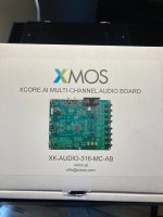
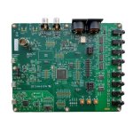
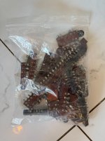
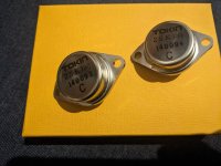
For Sale XMOS XU316 multi channel audio development board XK-Audio-316-MC-AB

SOLD
XU316 XCore™ Audio Processing Audio Evaluation Board

Used to develop my own custom board around the xu316 processor. The board is in good working condition and is loaded with the default XMOS USB audio software version 8.1.0 USB audio 2 channel demo code. This the multi channel audio dev board, and you can develop your own application with up to 8 channels working simultaneously, or just 2. The board features 4 stereo DACs, a USB interface, and flexible clocking options.

U26 clock generator chip has been replaced with a pre-programmed version of the same part (Si5351A-B04486-GT). Otherwise everything on the board is stock.

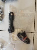
Includes 1 USB micro cable.

$100 includes shipping to anywhere in the US

IMG_1238.JPG

Attachments

  • IMG_1239.JPG
    IMG_1239.JPG
    337.1 KB · Views: 26
  • MFG_XK-AUDIO-316-MC-AB.jpg
    MFG_XK-AUDIO-316-MC-AB.jpg
    70.1 KB · Views: 32

Proline 3000 Speaker Membrane Slow Return Issue (First Repair Attempt)

Hi everyone,

I have a T.Amo Proline 3000 amplifier, and I’ve noticed something strange when playing music. After every bass kick, the speaker membrane doesn’t return to the neutral position immediately—instead, it slowly moves back as if there’s some kind of delay. It’s not exactly a DC offset (at least I’m not sure), but the speaker doesn’t behave normally and seems sluggish in response.

I tested the same speaker with a different amplifier, and the issue does not occur, so I’m sure the problem is within the Proline 3000.

This is my first time attempting a repair, so I would really appreciate some detailed guidance on where to start troubleshooting. If possible, please explain things in as much detail as you can so I don’t miss anything important.

What could be causing this issue? Could it be DC offset, bad capacitors, or something in the power supply? How can I test for these things? Any help would be greatly appreciated!

I only have a Multimeter to work with.

Thanks in advance! 😊

Kicker IX1000.1 Distorted Audio

I had a Kicker which had a 15V regulator resistor blown apart. R173, R174, R176 are also all open/cracked.

It can drive a lot of power, but its heavily distorted unless I turn the volume mostly down.

What is weird is when bending/twisting on the board i could make it produce a very loud hash noise, and then sometimes it would come out perfectly clean with no faults in the audio.

So, from what I learned on the CX600.1 I went ahead and resoldered the whole power output stage. No change in behavior. I decided to inductance check and ring check both output inductors, and they match.

The fact I can bang on the PCB and get the behavior to change (sometimes) leads me to believe theres an intermittent connection somewhere but im just not finding it. its hard to track down the search area without a schematic.

Posted a screenshot of the output from the amplifier, that is supposed to be a sinewave but as you can see, its anything but. All 4 output transistors have a PWM drive waveform.
1740185798600.png

Wee bit of help identifying what caps are what

Looking for a little basic help. I have a tube amp that needs biasing. In order to do so I gotta get right in there. The amp is also about 10 years old and I kinda wanted to look around at the electrolytics and at least understand them in case they need changing at some point soon.

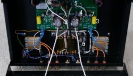
I have labelled the caps and my guess as to what they are. No schematic possible.

Hoping people can help me determine best guess as to what cap is what, especially filter caps so I can be extra careful.

I do have a discharge tool and understand basic safety and will be careful.

Any help is much appreciated

1. 2 x 470uf 450v (power supply?)
2. 1 x 220uf 450 (??)
3. 2 x 0.47uf 630 (output coupling?)
4. 2 x 47uf 450 (ps filter?)
5. 2 x 220uf 16 (input coupling?)
6. Some caps on a PCB that I could quite see and have no idea...
7. 2 x 220uf 63v (no idea?)

Attachments

  • IMG_20250228_163410.jpg
    IMG_20250228_163410.jpg
    53.3 KB · Views: 59

ML Folded Voigt Pipes ( ML TQWP or similar) construction design!

So, I know a lot has been said about this type of box, Good and Bad… and not all of that has been “ scientifically “ tested… (“ my mate told me this, so it must be true stuff”….)

So, I’m a “nobody, but I’ve built 11 boxes in a short time and I’m usually comparing the last 3 boxes that I make against each other to see if there’s progress ( some will say that I’m wasting my time) ( I keep 3 pairs of drivers so I can do comparisons with box construction,….yer I know audio isn’t an exact science)…

So, in my journey ( no, I don’t spend time with Horns rep), but, I started with “ Nandappe’s”design and I’ve been letting my ears and those of others guide my journey…
Yer, I can hear all the Computer warriors 🤡 crying, but it’s my gear in my room… I don’t expect a Computer program to fine tune that journey..

So, perhaps stupidly, I follow the ideas of Janos from “ Real World Audio “ You tube who says “ build it like a musical 🎶 instrument “, so my construction is much more like a guitar 🎸 top, than an MDF box..( MDF is Hateful stuff)..

Included in that idea is the finish that you give the timber..
A musician friend of mine suggested that timber oil sounds much nicer than varnish… and probably it does..
However I can physically feel a lot of vibration/ energy escaping through through the top of the box. ( yes it does have some stuffing there).
So, that leads me to think 🤔 that a straight pipe with a restricted mouth/ port might give me a purer midrange, but still keeping the bass balance…
Or maybe 🤔 I don’t need to, as the Midrange energy on a straight pipe would just bounce of the back wall instead of being released from the top of the box….

Ideas from people who have actually tried this stuff welcome 🤗 😊!!

Kicker KX2500.1 audible hiss

I have a KX2500.1 that was completely blown up so I rebuilt it. I noticed though with no input, theres a strong audible hiss from the speaker. like a waterfall. (This speaker is full-range btw).

I have not had this before when working on these amps, I removed the pre-amp board and no more hiss. So the problem is in the preamp.

I replaced both TL074C chips but the noise is still the same, not sure what's going on there.

I suppose the good news is, I can finger the LM13600 and listen to the radio station across the street :-D

Short of replacing the LM13600, I am not sure where to go with it. I did scope the output of OUT, and I can see the noise. it looks like an oscillation of around 13Mhz bursts repeating.

Tube newbie

Hi
I'm an electronics engineer that first got into electronics via the guitar. I built my first amplifier and took it to a job interview to show them what I'd made. I was 17 and got the job.
I went on to work in lots of different electronics fields including pro audio.
Fast forward 30yr and I'm interested in tubes to go with my terrible guitar skills.

Hello from Australia. I need your help with my Z5500 speakers

Greetings from Australia! I'm so glad to see so many others have enjoyed these speakers, looking at some of the threads here.. I've had my set for well over 10 years and have only just started experiencing an issue with them. figured I'd try my luck here. They turn on fine from the control pod but after a minute or two, the sound stops and the screen on the control pod goes mostly black (the blue led still is on). I have to turn the sub power switch off and back on and theyll work again for about the same amount of time. I did some research and found the easiest possible fix is replacing the fuse in the back. I went and got an identical fuse from Jaycar audio and replaced with but the same issue persists! i couldnt see this specific problem in any of the searches ive done but was hoping for some help on potentially fixing without needing to get too crazy and replace or bypass the control pod. thanks!

Hacking the Logitech Z5500

Like others on the net, I had something wrong with my Z5500 so they asked me to send back the controller and I ended up with an operational system and a "headless" one.

I now need a sub for a small system, and I figured I could somehow hack my Z5500 amp/sub for the purpose. After reading someone's post on how easy it was to access ins/outs and power switching on a 680 kit, since the connections had identifiable names on the PC board (FR, FL, RR, RL, etc...), I decided to take a look at the innards of the 5500.

After poking around in both the sub and the controller, I have to admit that there's a good reason Logitech asks for only the controller back: they've done everything possible to make it difficult for the DIYer to hack this speaker! Some of this stuff includes:

-No recognizable identification of any of the wire connections.
-Use of hot glue on the pcbs over many connection areas.
-Sanding of chip tops to prevent identification (mind you, the chinese subcontractor did a lousy job of this on my unit 😉 )
-The volume wheel on the controller seems impossible to take off. It feels glued (!). You can't clearly see the other side without removing it.

There's two main boards in the sub unit, possibly multi-layered: a preamp (5*4850's there) and the amp board with 8 heat sinked chips (7 chip amps + probably a regulator), but there's also some logic switching on the preamp board, probably responsible for turning on the amp. It doesn't look like it's a simple "switch-to-ground-to-turn-on" deal.

So in brief, it's not at all clear how to handle this. I may have to disassemble the amp board to see what chips are used, and just plug a diy preamp into the sub amp chips, bypassing everything else. I'll keep digging.

BTW, does anyone know a good way of removing this type of glue without damaging pcb and components?

I'm curious to hear from anyone else attempting/considering this.

ACA - help needed

Hi all!

Just finished building this amp and have issues with one channel not working. Once turned on, it just "farts" on the speaker, sounds like a 3 second discgarge noise for the lack of better explanation.

I've removed that channel out of the chassis and tested again isolated, same issue. All components check out measure vise (resistors and caps). Placement is exact as on the working channel. Did the resistance messurements suggested by the manual and here are the results (output connected, input and PSU disconnected):

Q1 -- S = 0, D = 4.96 k, G = 1 k
Q2 -- S=4.96 k, D = 1 k, G = 11.1 k
Q3 -- B = 5.65 k, C = 10.9 k, E = 4.96 k
Q4 -- S = 990, D = 1 k, G = 334 k

Is there any doc that shows how to test for correct voltages? Any help is greatly appreciated!

Thanks!!

REW FSAF revisited

Following @DcibeL post about using FSAF measurements across an Rsense of 0.1 Ohm, i open this thread.


First challenge was to find the latest Rew Beta, finally succeeded (only this morning), now i have to get into understanding the set up of Rew in combination with a RME Babyface pro FS.
Somehow my logic and that of Rew do not match very well yet, iow i have difficulty in getting it set up and calibrated.

But my checklist, once it is working, is to check the noise(or garbage ?) not only for drivers but also for the connecting cables.
  • Like
Reactions: TNT

Blown Sundown Salt 8 Amplifier

Hello ! I am working on fixing a blown salt 8 amplifier it looks as though one of the output fets died and took the output section along with the power section with it. I have repaired a few amps before but am no way an expert but do have the desire to learn more and get better at amp repairs. Ive established that the power section mosfets are IRF7530's but I do not know what the driver NPN/PNP transistors are, also the output section uses 24N40F's I was wondering would it be possible/ worth it to replace them with 24N50F's so the amp can handle charging in the 15v range a bit better ? From my understanding these SALT amps run very close to the output fet breakdown voltage when charging above 14.4-14.8 which leads to issues sometimes when charging any higher. Also what are the 5pin output driver chips there seems to be 4 of them directly in from of the driver card, rumor is they are all TC4452's but I just wanted to confirm. If these are blown is there a high chance it took the driver card with it as well? Any help would be greatly appreciated, I may ask alot of questions but I am trying to learn for future projects.
20230818_213930.jpg
20230818_234020.jpg
20230818_234012.jpg
IMG_20230828_161739_073.jpg

Luxman SQ38u

I recently purchased a Luxman SQ38u amp used. Seller stated that it's a 120v amp. I found out, while it was being shipped to me, that Luxman does not make a 120v version. The SQ38 transformer can be switched from 100v to 115v by Luxman for either market. This has led me to believe that the seller buys 100v versions and switches them himself misstating the voltage for the market he sells to.

To make a long story short, I can't tell if he actually did it and I am afraid the amp is working too hard at 120v. I can hear some buzzing from the power transformer, but also, a hum through the headphone jack that is very noticeable. Does anyone know how to check a transformer for it's operating voltage and the reason for the loud hum through the headphones?

Thanks!!

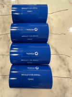
For Sale Clarity Cap MR (400V) capacitors, Solen capacitors

Hello all,

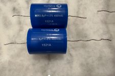
Purging some capacitors. All are used. All are roughly 50% of retail and include shipping and paypal in USA/Canada. All have leads that are roughly 1.25 inches (32 mm) long minimum.

Clarity MR 3.9uf (2) - $20 each
Clarity MR 15uf (4) - $30 each
Clarity MR 20uf (4) - $43 each

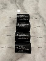
Solen 12uf (4) = $16 entire lot.

Thanks for looking!

Best,
Anand.

Edit: ALL CAPS SOLD!

Attachments

  • IMG_1055.jpeg
    IMG_1055.jpeg
    602.5 KB · Views: 104
  • IMG_1054.jpeg
    IMG_1054.jpeg
    625 KB · Views: 85
  • IMG_1053.jpeg
    IMG_1053.jpeg
    515.2 KB · Views: 97
  • IMG_1057.jpeg
    IMG_1057.jpeg
    620.2 KB · Views: 101

A Stereo 6N6P Hybrid Line stage w/Parafeed Output Transformer

What it is:
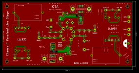
A single tube hybrid parafeed line stage using a single 6N6P - should work with the 6H30 as well utilizing Lundahl LL1930. This is not intended to be an ultimate design, but a cost effective design with transformer.

Each channel comprises half the 6N6P, a cascode CCS using DN2540 or similar, the transformer and a DC blocking capacitor. LED bias is used. Resistors are 1206 or 2512 SMDs.

There are two options for connecting the transformer; jumper configurable; one is directly to the plate of the 6N6P, the other is to the source of the lower device in the cascode. The LL1930 expects to see a source impedance of 4.5K or so and provision is present for padding resistors to satisfy that requirement. (There is obviously a small loss in gain.)

Gain is approximately 8 - 9dB
Frequency response 20 - 30khz @ 1dB or better
Output impedance should be < 150 ohms typical.

Distortion is predicted at 0.3% at 2Vrms out and is predominantly 2nd with 3rd about 20dB further down, not betting that is an accurate prediction. [Edit: This was way off, THD is typically 0.006% or less]

Both balanced and unbalanced output is possible, input is unbalanced only and is intended for connection to a 50 or 100K pot or stepped attenuator. I will be using a 50K stepped attenuator of dubious origins. (read inexpensive)

I've completed the design, but have not built or tested it yet, that's next.

Power supply will likely be unregulated and lightly filtered since the PSRR will be reasonably high. I will design that next.

Power transformer is an open guess at this point, raw DC voltages in the range of 230 - 300VDC are required. Filament power may/may not be AC, proximity to sensitive circuitry may drive the use of a cheap monolithic regulator for the filament supply.

I ordered the PCB from JLCPCB tonight and will order the rest of the parts (DigiKey) in the next few days.

The name is a bit of an inside joke, I recently designed a line stage using some left over discrete jfet input op-amps I designed which uses a heavily filtered dc to dc converter for power and is very compact. I called it the Cheesy Line Stage because it was supposed to be cheap. (It really wasn't) Trying to keep entertained in these times so I am doing cheesy line stage designs, the last was solid state, this one will be hybrid. After this I will move on and do something else.

Attachments

  • schematic.png
    schematic.png
    24.6 KB · Views: 2,485
  • Parafeed line stage V1.0.pdf
    Parafeed line stage V1.0.pdf
    55.2 KB · Views: 496
  • Topside.png
    Topside.png
    97.4 KB · Views: 2,337
  • 1930.pdf
    1930.pdf
    148.8 KB · Views: 379
  • 20211001_191839.jpg
    20211001_191839.jpg
    669 KB · Views: 2,165

Did anyone try one of these ES9028/ES9038 DAC kits?

Hi,

I am considering building a DAC and think these from DIYINHK based on ES9028PRO or ES9038PRO look interesting:

ES9028PRO ES9018 32bit Audio DAC PCB - DIYINHK

ES9038PRO XMOS DSD DXD 768kHz USB DAC with Bit-perfect volume control and SPDIF input - DIYINHK

Did anyone ever build and/or listen to one of these? Any experiences to share?

Thanks in advance,
Maartn

Changing QUAD 405 Input Impedance

Hello all, this may be a shot in the dark but i have read some excellent threads here so i know there are some well informed and experienced folk around !

I have a Quad 405 (mk1) which was modded some moons ago by a gentlemen named Ivan who was residing in London at the time.
Unfortunately i cannot remember what mods i had done exactly, but i do know it has dual power supplies* and rca inputs added.
(I've added pictures of the internals of the amp to this post)
Unfortunately i lost contact with him and have been unable to locate him.

I am going to try and use a potentiometer (alternatively named a passive preamp) inbetween my audio interface's DAC and my Quad 405.
The audio interface is a Fireface800 and the Output Impedance is 75 ohm.
So going by the rule of 20x, i am going to use a potentiometer at 1500 ohm, and then multiply that by 20 for the Quad = 30,000.
I believe the Quad 405's original Input Impedance is 20,000k, and i would be ok with that, however Ivan informed me back then that he added a resistor to the Input Attenuator which brought the Quad's Input Impedance down to 6800k.
(ah, i've just remembered that the Quad's Input Sensitivity was adjusted to 1.5v)

So my question is, can i simply remove this resistor in hopes of returning it to 20k, or does it involve making other adjustments ?
Or maybe even -can i increase this amount to 30k without complex work.
I am not proficient at circuits and electronics, but i am competent and experienced with soldering and getting simpler tasks done.

Any input at all would be most appreciated, thank you !

20250226_163456.jpg
20250226_163503.jpg

20250226_163511.jpg
20250226_163525.jpg

20250226_163557.jpg

20250226_163628.jpg
20250226_163650.jpg
20250226_163747.jpg

20250226_163804.jpg
20250226_163825.jpg
20250226_163853.jpg
20250226_163931.jpg

Soldering Litz large inductor

Hello all.

During the pandemic, I purchased an SB Acoustics Arya kit from Solen (including beautiful white cabinets) for a reasonable price. I am now getting around to building it. However there were out of pre-built crossovers, so they sent all the parts from their stocks.

For the low-frequency crossover, SB Acoustics specifies a relatively cheap iron-core 3.3 mH inductor wound with 1.2 mm diameter wire. But Solen included instead their massive 4" diameter X 1" high Litz inductor (part # L143.3), wound with 1.4 mm Litz wire (7 separate conductors in hex pattern). No complain about that substitution--kudos to the company!

The inductor wires are insulated with "Red Polyurethane Polyamide Enamel" as the website states.

How should I strip this insulator, prior to soldering, so that all 7 conductors are connected? I plan on using 63/37 rosin core solder because this is what I have in large quantities... Is the flux enough to strip the insulator off?

Any suggestion welcome!

--Christian

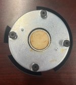
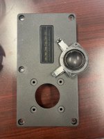
Need help spec'ing replacement tweeter for Dali Helicon 400

Hey all! This is my first non-introduction post.

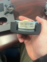
I recently picked up a pair of Dali Helicon 400 tower speakers. They sounded great but there was noticeably less output from one dome tweeter. I've had good luck bringing tweeters back to life by cleaning up the old gummy ferrofluid and putting new stuff back in. I was attempting to disassemble the tweeter but the voice coil was stuck in the magnetic groove. Turns out the magnet had shifted and pinched one side of the voice coil. It still kind of worked but at a much lower volume than the other side because it wasn't moving freely. The force needed to pull the pinched piece out of the magnet broke the voice coil so now its dead dead.

The tweeter assembly is a combo 1" silk dome tweeter along with a ribbon tweeter. As best as I can tell the dome tweeter was made for Dali by ScanSpeak. Looking at what specs I can find, the dome tweeter seems closest to a ScanSpeak D2608/9130 or at the very least that is what the Dali version is based on.

Replacement tweeters are only sold by Dali as the entire assembly (mounting plate, ribbon, dome) for $1350!!!! Needless to say, that's just a non-starter here.

I work in manufacturing and have access to CNC equipment and 3D printing machines so I can modify the mounting plate to accept pretty much any modern tweeter. Though the D2608 seems most like the original tweeter, I am looking at two Morel models that would be much easier to mount (smaller footprint) and similar specs-- the Morel CAT408 and ET448.

Ideally I'd like to not have to mess with the crossover but I realize that might be inescapable. Do I just replace the domes on both sides with something close and hope it works out? Do I replace the whole assembly with a single modern tweeter and modify the crossover accordingly as I've seen in some posts with similar Dali speakers?

Just looking for some advice from people smarter than I and hoping to learn a bit along the way.

Attachments

  • IMG_6807.jpeg
    IMG_6807.jpeg
    583.1 KB · Views: 49
  • IMG_6808.jpeg
    IMG_6808.jpeg
    1,013.5 KB · Views: 50
  • IMG_6809.jpeg
    IMG_6809.jpeg
    342.8 KB · Views: 45

Rythmik DS1200 CI Servo 12" Build

Getting a build pulled together with Rythmik's 12". I have been ok'd by management for one sub, will have to see if I can negotiate a second when this is done. Rythmik doesn't offer their 15s for diy anymore, but the 12 is the better fit in my space, especially if I get a second.

My cabinet will be 14" wide 23.5" tall and 17.25" deep. More subs should be narrow and tall instead of squat and deep. With the rounded front corners I will be able to finish with a 2x4' piece of veneer. Will have it match my Bolivian rosewood mains.

Extensive bracing, may not be optimal, but should be more than enough. Going to sit on some SVS sound path feet, tested those on my mains and had great improvement in the tactile bass. Nothing you could measure, but what I could feel in my very live wooden floors was much less buzzy and more punchy.

Front baffle is 3 layers of 3/4" mdf with a generous bevel to the woofer. Exploring ideas still on how I want to put a grill on, sub is right on a walkway and want to protect the surround.
1000044471.jpg
1000044591.jpg


More clamps...
1000044603.jpg

1000044640.jpg

1000044641.jpg

Adding a secondary tonearm on my TD-126

Hi everyone,

Chaing cartridges on my SME 3009 III It is a bit of a pain in the backside.

In the past I had 3 turntables.. That's a real state consuming not to mention the cabling and stuff.

Now I want some simple, clean setup with two tonearms to hear and test different cartridges without the drawbacks of changing the records, messing with cables.

Something simple.. I don't want to have a mad scientist cartridge lab lying her like the example below.


4dbd9efeedad0e2ced6dc5fd1f2dccd7.jpg


Any considerations? I have a Thorens TD-126

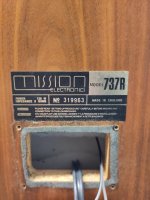
Mission 737R - Muffled, fuzzy sounding on one channel help appreciated

I have a pair of 737R's which I love, but recently one channel became fuzzy and muffled. I have carried out some basic inspection, but at this point not done any real testing so any advice would be great.
Attached are a couple of pics of the data plate and crossover on the speaker with the issue, nothing appears burnt out, or smelling such, although, I guess the shellac, has all dried and cracked off when I touched it, would I be better off to remove all components and remount on a board I then attach on the inside of the cabinet? I have taken a look at the coils on both woofer and tweeter, both of which visually appear fine from initial inspection. The only issue I found was that the studs for both +/- terminal were loose, which I have now tightened, electrolytic's appear visibly okay, but I understand these do not age well and perhaps should be replaced anyway.
In fact I am also looking on this as an opportunity to upgrade the units as the rubber surrounds and the poly cones on both speakers are clearly old and no longer flexible in the way they once were. So any advice or suggestions on any of this would be very much appreciated. Thanks, Stew

Attachments

  • 1000047977.jpg
    1000047977.jpg
    387.7 KB · Views: 78
  • 1000047979.jpg
    1000047979.jpg
    309.3 KB · Views: 78

RCF ART710A MKII silent

Hello,

I've seen quite a few of these RCF active speakers but mostly with an issue in the SMPS - in one case the main SM controller, in the other an NPN buffering the signal from the 555.

The speakers I'm talking about seem to have exaclty the same layout, them being MK2 or MK4, with the same long black PCB.
In this case the power supply seems to work, I get seemingly all the voltages at the secondary (15V, -15V, 10V, -8V, 3.3V, 1.8V).

If I was to turn the power on I'd see the amber LED by the microcontroller turn on for a few seconds (possibly a sign of initialising) and then turn off. At that point all the LEDs at the back of the unit become lit (Status, Signal, Limit) and the speaker is silent.

There's a power off sensing circuit which I'm assuming is managed by the microcontroller, since the amber LED comes back on immediately after I turn off the power switch (before the supply rails start dropping), I can probe somewhere around the microcontroller a square wave with same frequency to the mains. This makes me exclude the microcontroller from the equation.

I've tested all SMD caps concerning the DSP and microcontroller area but couldn't find shorts.

I can't see any clock on the DSP MCLK pin, while there's a faint triangular wave on the adiacent OSCO pin, where the crystal connects.
The DSP is definitely getting power, though it doesn't seem to heat up or be running.

I'm not sure if anyone ever came across a schematic for these, it is pretty hard to trace those tracks on a black PCB.

How would you go around testing a class D amp in this case?

Alex

iFi Audio Model "micro iPhono2": Creating Schematic - help needed

iFi Audio Model "micro iPhono2" (iphono-2): Creating Schematic - help needed

Currently I am creating a schematic diagram of this MM/MC RIAA head amp:
micro – iPhono2
iFi iPhono 2 | The Ear
Review ifi iPhono 1 & 2 (und eine kleine Warnung) - Phonovorstufen und Ubertrager - Analogue Audio Association

For all used IC's I don't find out the right type number and thus I don't find the associated datasheets (except U3/U4: HC4066A in the TSSOP-14 outline = MC74HC4066A):

U1: EAA 5SA (SOT23-5, go to last image), unknown, maybe MAX828
U2: OV 4627A - maybe quadversion of Burr Brown's OPA 627 made for iFi-Audio (TSSOP-14, go to first image)
AMR/iFi audio's Content - Page 2 - Computer Audiophile
U5: OQ = H05 or 0Q = HO5 (SOT23-6, go to second image) - unknown.

Who can find out this for me ?
Thank you very much.

This URL's don't provide the wanted information:
http://chip.tomsk.ru/chip/chipdoc.nsf/vc1!readform&view=smd&cat=J&start=1&count=500
http://www.dl7avf.info/charts/smdcode/cj.html#TOC
http://www.marsport.org.uk/smd/mainframe.htm
E96 codes SMD resistors
https://learn.sparkfun.com/tutorials/resistors/decoding-resistor-markings
Transistors:
http://www.dl7avf.info/charts/smdcode/c2d.html
Q1 12T = 2N7002
Q2 2X = 2N4401
Q3 3FW = BC857B/BC557B
Q4 2XZ = ?? maybe 2N4401
Q5 38W = PMBFJ108/J108, Made in China - go to page 2 of 9 under
https://www.nxp.com/docs/en/data-sheet/PMBFJ108_109_110.pdf?
Q6 1BW = BC847B/BC547B
Q7 12T = 2N7002
Q8 12T = 2N7002
Q9 12T = 2N7002
Q10 2X = 2N4401
Q11 NU
Q12 12T = 2N7002
Q13 2X = 2N4401
Q14 12T = 2N7002
Q15 38W = PMBFJ108
Q16 6g = BC818-40/BC338-40
Q17 6g = BC818-40/BC338-40

Diodes
D1 WL = Zener 15V
D8 T4 = 1N4148
D7 SV = Zener 3V6
D9,10 WB = Zener 6V2
D5/D6: J11 923B = Zener, 8V2
https://www.onsemi.com/pub/Collateral/1SMB5913BT3-D.PDF
basics for iFi’s revolutionary ‘TubeState’ design
https://ifi-audio.com/portfolio-view/pro-idsd/
https://ifi-audio.com/portfolio-view/x-xdsd/

Attachments

  • DSCF3757.jpg
    DSCF3757.jpg
    984.1 KB · Views: 1,177
  • DSCF3763.jpg
    DSCF3763.jpg
    911.6 KB · Views: 1,115
  • DSCF3769.jpg
    DSCF3769.jpg
    979 KB · Views: 1,104

Acoustat TNT 120 hum

I have a TNT120 that I have owned since 1984 along with a AGI 511a pre amp and Magnepan MG1b's and just updated to LRS+'s.
I have always had a very low hum out the speakers from the beginning that couldn't be duplicate at store. It still happens with only the amp plugged into 110v socket with the ground connected or not and the speakers connected with Kimber wires. The manual states "The only Way to prevent this hum is to float this ground".
Any help would be nice. Thanks Larry

Hello from the rainy Pacific Northwest!

Hello all! I've used DIYaudio forums forever and have built few Nelson Pass projects over the years but I've always managed to find answers in existing posts and have never posted myself. I've built the band camp amp, Akitika preamp and Bob Latino Stereo 160 tube amp. I've also repaired, refoamed and upgraded many speakers and crossovers. I need some help spec'ing a replacement tweeter which may require changing the crossover which is something I've never done and need some help with. So this post is in the introduction and I'll buzz over to the speaker section to post my question

I'm in Portland, OR and happy to be an active poster now.

Treble Clef Audio TCA-M Active

First came the B&W snail, now comes the treble clef.

1740736717398.png


As soon as I saw it, I thought the minimal baffle setup should allow for very smooth directivity transition.


1740735448423.png
1740735418314.png


Developed with bi-plane polar measurements in REW, mixed phase EQ, multi-amps, 3D printed or CNC parts, IKEA bowls, just like what you have done!

@5th element @CharlieLaub @DcibeL @hifijim @Juhazi @racingpht @vineethkumar01

1740737326129.png


with love from Denmark

https://trebleclefaudio.com/

Attachments

Center to go with Heissman DXT Wave?

I’m considering building the Heissmann DXT Wave floor standers. I’m leaning toward the active build, but might go passive. These will be used for stereo music and as main left/right for home theater.

Before settling on the build, I’d like to find a center channel design that is compatible (the same speakers, ideally). On the DXT wave website, Alexander says to use the DXT-mon as a center channel, but there’s no way my wife would let that sit below our TV. I need to find something that looks somewhat like a typical center, meaning short in height and long horizontally.

Does anyone know a design that might fit the bill? I was wondering if I could even modify the DXT wave design to lay sideways in a W-T/M-W arrangement. I’m not too keen on modifying that design, especially since the circular baffle cutout detail is pretty critical to getting to DXT tweeter performance right. Although maybe that isn’t very important when laid horizontally.

Has anyone else here actually built the DXT wave? i’ve seen a number of people say it’s a good design, but I haven’t seen any kind of build logs or first hand reviews.

Thanks for any advice!

Reducing Record Surface Noise - I want to know all Approaches

If there are perfect clean records without scratches in use, there is still a very heavy hiss and noise audible between the tracks. Much more than the inherent noise even from cheap and simple RIAA designs with µA741 or 2-transistor RIAA solution.
This record surface noise strongly depends also on footprint of stylus (e. g. shibata, elliptical or hyper elliptical profiles) so as the selected tracking forces.
A spherical styli diamond provides bad results.

Best known styli for high quality are follow:
https://www.youtube.com/watch?v=rEV0-q18-oo
But there are many more (e. g. VDH-styli etc.).


What kind of styli on the cartridge and which appropriate tracking force is ideal in order for lowest mechanical background noise while record playback ?
Which influence are to expect from the tonarm ?
Thank you for advices.

This threads don't provide any advices:
Surface Noise!! | Steve Hoffman Music Forums
What limits surface noise on vinyl? | Steve Hoffman Music Forums
Surface Noise!! | Steve Hoffman Music Forums

LXMini ASP - Balanced config?

I've got a pair of LX521.4 Mg ASP-powered speakers that I love, but had to put into storage while I'm spending a year or two on my sailboat. I have a pair of Genelec 8320a, but I'm really missing my "magic" speakers, so it's time to build a pair of LXMinis.

I'm going to start with the ASPs. At the end of Nelson's article, he suggests balanced mode requires two boards. I just wanted to verify what I think that means before I order them.

Does that mean one board is connected to the positive pin, the other board is connected to the negative pin, and the neutral is connected to ground/chassis? My preamp and amp (4-channel) is all XLR (truely balanced, not fake balanced.) Is this the right way to do it?

Can I run them off of a 24V battery? I was thinking in terms of audio quality and black background. If a wall-wart is sufficient, that's fine.

I'll go ahead and ask the last question which isn't of immediate concern, but eventually might be. I saw a post on OPLUG where someone built a double-barreled config for the lower speaker with the upper speaker pointed at the listener between the two lower. SL liked it and suggested one could lower the crossover point to 35Hz to allow it to play louder since the cones were not likely to max out the baskets as easily. (decrease low-pass filter in relation to high-pass filter and extend the bottom end a little.) Is that easily done on the circuit with a new cap/resistor pair? I found the Microcap simulation files and will study those in the next few days.

For Sale Various Parts: Some Junk, Old, or Free

I have the following parts available—most of them are free! Take some or take all.

Pricing: All prices are net to me. Please add shipping costs from Brooklyn, NY 11211, and 3% fees if paying via PayPal (as a purchase) or Venmo (as a purchase). No fees are required if paying via PayPal (as a friend), Venmo (as a friend), Zelle, or bank transfer.

Free Items:
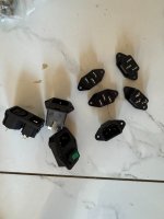
  • AC Sockets
    Free
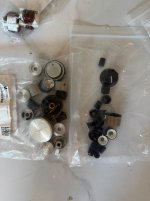
  • Assorted Volume Knobs
    Removed from reel-to-reel or other older devices. Some unused, mostly old and used.

    Free
  • Old Tube Sockets
    Removed from reel-to-reel. Used
    Free
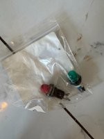
  • 2x Old Light Bulbs
    Removed from reel-to-reel.
    Used
    Free
  • 2x New Light Bulbs
    Specs unknown. Should be new.

    Free
  • Used Solder Lugs
    Removed from reel-to-reel.
    Free
  • Corner Screw-to-Banana Plug Adapter
    For using banana jacks in old Dynaco screw terminals.

    Free
  • Corner RCA Jack
    Gold-ish plated.
    Used
    Free
  • Pin Speaker Jack
    Used
    Free
  • Assorted Cheap Tube Sockets
    Octal, noval, UX-4, some ceramic. Mostly unused.

    Free


Items for Sale:
  • 6x Small Socket (Noval) Standoff
    Never used, purchased from Japan.
    $20
  • 8x Large Socket (Octal) Standoff
    2x Never used, 6x poorly painted, purchased from Japan.
    $20
  • 2x 2-Prong Power Cords
    Originally purchased to replace old cracked wires in Dynaco ST-70. Never used.
    $5 for both
  • 2x Kemet Chokes / Filters
    250V 20A 0.8mH, DCR = 4.7mOhms. New
    $5 for both
  • AC Sliding Switch
    Purchased for fixing Dynaco ST-70 and similar older devices. Mostly used
    $15
  • AC Panel Outlets
    Purchased for fixing Dynaco ST-70.
    $40

Attachments

  • IMG_1676.jpeg
    IMG_1676.jpeg
    342.6 KB · Views: 38
  • IMG_1664.jpeg
    IMG_1664.jpeg
    320.1 KB · Views: 35
  • IMG_1665.jpeg
    IMG_1665.jpeg
    252.3 KB · Views: 37
  • IMG_1666.jpeg
    IMG_1666.jpeg
    297.1 KB · Views: 38
  • IMG_1667.jpeg
    IMG_1667.jpeg
    355.7 KB · Views: 36
  • IMG_1668.jpeg
    IMG_1668.jpeg
    298.8 KB · Views: 37
  • IMG_1669.jpeg
    IMG_1669.jpeg
    267.2 KB · Views: 37
  • IMG_1670.jpeg
    IMG_1670.jpeg
    267.6 KB · Views: 37
  • IMG_1671.jpeg
    IMG_1671.jpeg
    309 KB · Views: 39
  • IMG_1672.jpeg
    IMG_1672.jpeg
    367.3 KB · Views: 36
  • IMG_1673.jpeg
    IMG_1673.jpeg
    309.1 KB · Views: 48
  • IMG_1674.jpeg
    IMG_1674.jpeg
    408.6 KB · Views: 44
  • IMG_1675.jpeg
    IMG_1675.jpeg
    240.9 KB · Views: 48

Venting capacitors to their demise

Last night, for the 1st time in 40+ years of owning/using a soldering iron, I vented two power supply capacitors via reverse polarity error. I stuffed a power supply PCB backward. It was majestic and delightful to watch as though a genie was rising from a two-tower lantern, yet horrific and toxic. I'm fortunate they didn't explode in my face. Shame on me for not putting my VARIAC back together. I'll get on that asap.

Attachments

  • Screenshot 2025-02-25 172758.jpg
    Screenshot 2025-02-25 172758.jpg
    235.5 KB · Views: 112
  • Like
Reactions: stv and metaphile

ADAU1701 Pre-Amp I2S distribution

if this is not right place for this topic, I'm sorry. I'm new to diyAudio and this is the first post. My experience in electronic design is close to zero, there is only basic knowledge.

There are a lot of threads regarding this, but i was not able to find a decision.

My plan is: building a up to 8 Chanel pre-Amp proto with this chain:

4xSpdif in -> I2S->Adau1701 ->(up to) 4xDAC -> Volume IC -> preAmp/Buffer -> RCAout

Parts:
Spdif in -> unclear
Adau1701 ->Wondom APM2
DAC ->PCM1502( maybe upgrade later)
Volume -> PT2258
preAmp/Buffer -> update 23.01.2025 from youtube channel "Franks Werkstatt der Lautsprechertechnik"
uC for Control -> not sure

Input sample rate: 44,1kHz.

At the moment i am working/struggling on I2S distribution, I2S input (with MCLK) comes from Arylic pro V3, output is Adau1701 Dac for debugging and a PCM5102 I2S Dac board.
APM2 is working as slave (MCLK in) with 16Bit output. All signals visible on scope.
1.) BCLK and LRCLK wired simply parallel to Arylic, PCM5102, Adau xCLKin and Adau xCLKout --> Adau DAC works, PCM5102 works not
2.) changed to 100Ohm in series at Arylic BCLK and LRCLK --> outputs are working, but some clitching noises every 10- 20s also on booth outputs
3.)resistor changed to 50Ohm --> same as no 2, but with much more noise

The Signals of Data in/out and LRCK looking good, in my opinion, but BCLK get more worse with each additional I2S connection. Because of the target to have up to 4 IS2 DACs, i think it is not solvable wit some Rs and Cs.

So, i want to buffer the signals with 74hc125, one behind I2S in and second behind APM2. To prevent timing problems all signals should be buffered also MCLK and DataIn/out. Good Idea or bad? Is one buffer able to drive 4 of these dacs, or ist better to use more buffers?

grateful for any critics, hints or opinions

Minimum depth sealed speaker box fixed to the wall

I have an impression that in-wall mounted speakers have very strong advantages, mainly in significant bass boost due to radiation in a smaller sphere fraction and much reduced most audible reflections coming typically from the wall behind. But as I understand there are two main practical problems – 1) proper bass requires volume not practical in wall, 2) it is a significant renovation project. So I have thought if there are significant acoustic compromises if I do a much less destructive 😉 concept which is a sealed speaker box with minimum depth fixed to the wall plus a subwoofer box placed in a suspended ceiling above. The latter I have already submitted and got a nice feedback here https://www.diyaudio.com/community/...ons-in-a-dropped-ceiling.421710/#post-7883856
And in the meantime the former part has flashed on me 🙂
So I would like to ask for your feedback and maybe experience sharing on it, in particular on things like:
1) Do you know if there are such or similar commercial products ?
2) How to assess the impact of the protruding of the box front sth like 10 cm ? These effects of increasing perceptions of distinct reflections change somehow gradually with the protrusion distance but is there some relatively simple intuitive model to roughly assess this impact ?
3) Related to 2) – what importance might the width of the baffle have ? And optionally adding some angled/triangular-shaped side wings to the front ? – that would avoid a single 10-cm step - but again is it more important that there is no step or rather that it it actually becomes a wider baffle ? I guess with a step ther wll be higher fluctuations that look bad to the eye but might not be significantly audible as they probably be narrow-band - so maybe not worth the extra effort ?
There is a simiIar thread with some relevant and useful insights already https://www.diyaudio.com/community/...that-becomes-effectively-in-wall-size.423124/
but I think my concept is a bit different and I am interested in more perspctives 🙂|
  • Like
Reactions: camplo

Cardioids for Dummies

About a year ago, I bought five of the Monoprice speakers because they were on sale for 60% off. I ran them for a while as a bizarre ambio setup in my office.

I can post docs on that.

When Erin H posted the amazing measurements of the Kef Blade Meta 2 a few weeks ago, I decided to mess around a bit with making active cardioids using "off the shelf" speakers.

polar-patterns-recording-vocals.jpg


This is what a cardioid radiation pattern looks like.

maxresdefault.jpg


These are the speakers: "Monolith by Monoprice Encore T5 Tower Speakers." The pics in the photo are the Encore "T6" which is 20% bigger than the T5s that I have. In other respects, they're very similar. Here's some measurements from Erin: https://www.erinsaudiocorner.com/loudspeakers/monoprice_encore_t6/

There are a couple of (obvious) ways to make an active cardioid:

1) You can put two speakers back-to-back, separate them by one quarter wavelength, put them in the same polarity, and create a Gradient Cardioid

2) You can put two speakers back-to-back, separate them by one quarter wavelength, put them in opposite polarity, and create a End Fire Cardioid
  • Like
Reactions: Arez

Output stage completely blown during idle conditions

Hello again,

Sorry for yet another post but found this one a rather interesting scenario. But I was running this amp for an hour or 2, ran amazing without an issue until the short circuit detection kicked in. I turned off the amp and found a immediate drain of the caps. I turn the amp on after a bit, everything back to normal. Short circuit kicks in again this time the power supply was completely shorted considering the nice screeching sound before shutting off itself. The weird thing was only Q16/Q17 where the only devices damaged which is most likely an indication that the bias current somehow spiked to critical levels. The VBE servo and the power darlingtons where thermally coupled to a large aluminium heatsink.

Changes I have made:

Changed the VAS and CCS transistors for the output stage from KSA992/KSC1845 to 2SA1201/2SC2911 in case the VAS and CCS where getting hot considering they are only small BJTs with 6mA going through them

I tested the removed VAS and CCS transistors and they appear to still be transistors and not a resistor, diode, or jumper.


1740439328014.png

DAC AK4499EX Project

Hi,
It is my second project of DAC, first was on AK4499EQ but after fire in AKM factory projest is useless. Now AK4499EQ chip is to expensive, over 1k USD in Ebay. Now afrer relese new chip on Munich AudioShow I downloaded Datasheet and started designing the new DAC on AK4499EXEQ.

DAC will be Dual Mono, one PCB DAC + Power Supply - one chanell. DAC will be working in Asynchronous mode.
Now it looks like this:

obraz_2022-07-29_183450150.png

Mid-woofer for Seas E0055/T35C002

I need to find a mid-woofer pair with my Seas E0055/T35C002.

Needs are as follows:
Sealed Box,
1500HZ crossover, passive
6-8" mid-woofer,
T35C002 in waveguide(not decide yet)
listen in a small room, nearfield, low spl
Below 500$ for a pair
F3 >=60, my dual Wavecor SW275 Subs will do the sub-bass and part of the mid-bass.
Vb<=25L


I have some candidates in mind but I never use T35C002 before. Please give me some advice.
Candidates are as follows:

Tang band w6-1721
Wavecor wf223 bd01/wf223 bd02
Seas 18W/8531G00
maybe more,

I'm in China so I can only buy brands as follows:
ScanSpeak
SEAS
Wavecor
Tang band
Eton
SB Acoustic
Purify
Morel
Volt

Thanks in advance!

LJM L12-2 ver 4.2 - help me wire this plz

Hey folks, after watchin a number of videos from mr @michael beeny I pulled the trigger on L12-2 and received version 4.2 of this board.
I am a little confused about how things are supposed to be grounded. Can someone please help me check if the following wiring scheme is correct?

Option 1:
  • connect the speaker protect grnd to amps
  • connect amp grounds to PSU

Attachments

  • Screenshot 2025-01-02 at 17.16.45.png
    Screenshot 2025-01-02 at 17.16.45.png
    1.2 MB · Views: 243
  • Like
Reactions: sonicles

Low level of Samsung optical output

Samsung TV Optical Output - Low Audio Level?

Hi everyone,

I have two different DACs: Canary Daart and Muse Audio DAC6X. I connected both to my Samsung TV's optical output and played a 0dBFS test signal from the YouTube app on the TV.They both gives 300mV pp on 0Dbfs named 1khz 60 minute video and gave 500mV pp max on another 1khz videos.I read everybody tells 2V rms should be get from dac RCA outputs. But mine is much smaller than this.

I also tried adjusting the PCM output settings on the TV, including setting it to the maximum available output level, but nothing changed. The audio level remains the same.
Possible reasons I can think of:

Does Samsung TV’s optical output reduce the audio level?
Is the YouTube app on the TV not outputting a full-scale (0dBFS) signal?
Is there an adjustable digital output volume setting on the TV that I might be missing?
Has anyone tested or measured the optical output of Samsung TVs? Any insights would be appreciated.

Thanks!

Attachments

  • 20250227_120604.mp4
    6.9 MB
  • 510EyRm0X0L.jpg
    510EyRm0X0L.jpg
    46 KB · Views: 29

Seeking ideas for Technics SU-V460 with a blown SVI3205 power amplifier module...

I've got a Technics SU-V460 with a shorted SVI3205 power amplifier module.

I was just wondering if anybody has any bright ideas on how it could be brought back to life?

Has anybody been able to crack open this module and repair it using normal parts?

Unfortunately, the B+ lines seem a bit high (+/-45.5V) to substitute with an LM3886 or similar board.

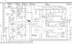
Please see schematic below... any ideas welcome.

Thanks,

Attachments

  • Screenshot From 2025-02-27 22-39-39.png
    Screenshot From 2025-02-27 22-39-39.png
    397.3 KB · Views: 58

Compressor question

Hello. I am assembling a homemade two-way speaker with an active crossover and would like to add low-frequency boost to achieve interesting sound at low volume levels. Having studied the topic a little, I came to the conclusion that I need a limiter or a compressor. Inspired, I turned to a group of audio enthusiasts with a request to help find a simple compressor circuit. This is a circuit on an optocoupler and a dual operational amplifier, quite simple. I was able to make a primitive printed circuit board and began testing it with only a superficial understanding of how to set it up. After fiddling around for several days, I realized that nothing was working. Since the compressor is quite slow and affects the entire incoming signal, there were volume jumps or a drop in volume in general if a long release was established.

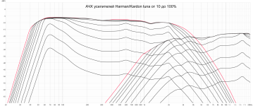
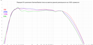
In general, I am interested in portable speakers and have tried many different ones. The models that stood out most were JBL and Harman/Kardon. Their peculiarity is that low frequency compression occurs without any noticeable effect on other sounds, and to be honest I don't really understand how they achieved this. Ideally, I would like to understand their signal processing algorithm and assemble something similar for myself. Maybe someone has studied this topic and can tell me more?

Attachments

  • HK luna amplifiers 10-100% dB scale.png
    HK luna amplifiers 10-100% dB scale.png
    484.9 KB · Views: 38
  • HK luna amplifier with different lenght sweep at 100% volume.png
    HK luna amplifier with different lenght sweep at 100% volume.png
    243.2 KB · Views: 40

PEECEEBEE V5 GB

_________________________________
Update: Revision 1 (Feb 23 2023)

In the board silkscreen a few things have been changed thanks to Gary's input. Component markings have been improved and now it should be easier to read the numbering. Also a few components were missing in the schematic (that were present in the layout). This has also been corrected.

The pre-driver transistors Q17/Q18 have been oriented correctly to put their flat face in parallel with the drivers Q25/Q26 so that they can be properly thermally coupled with the driver transistors using zip ties. This thermal coupling ensures output bias stability.

Update: (July 25 2024)

Schematic and BOM updated with latest component changes for best operation. Namely, R19, R20, C15, C16. PCB layout and silkscreen indications remain unchanged.
_________________________________

Hello everyone.

Here is the latest version of PeeCeeBee, the V5. PCBs will be available through group buys in this thread. For the questions/discussion thread please follow this link >here<.

I have been on it since early 2022, and after a long series of experiments and listening tests the design was finalized in October end. The concept-build was done in early January and after some tweaks the amp took its current shape in late January this year. By that time the prototype layout was also completed and subsequently I got a pair printed, and after carefully listening to the prototype build for some time I felt that sound-wise the PeeCeeBee has moved one more step forward and it was time to release it.

This time we let the Lateral MOSFETs go and adopt the mighty Vertical MOSFETs, then vertically invert them and short them gate to source, then let them pass only a few tens of milliamps! The output devices are bipolar transistors. Why let the Laterals go? Well, I can't get genuine ones anywhere except Profusion PLC (Exicon). After the market basically went empty of Laterals following the pandemic, I realized I need to move on. But move where? Verticals are very nice devices when very hot, but not so nice at room temp. Meanwhile many audio friends suggested that I should go bipolar, and I thought "ok let's go bipolar". But after listening to the first bipolar-output peeceebee concept in June last year, I wasn't impressed to say the least. But bipolars are room-temperature-happy devices and many options are available from many manufacturers. This was intriguing. So I thought let's see where this goes. Experiments began. And here we are.

Description:

The PeeCeeBee V5 is a bipolar input - bipolar output symmetrical current-feedback amplifier with 32 transistors per channel (yes). And it still sounds musical! Some of the transistors are connected in such a way that makes it look like they are turned off for-ever. Well, they are turned off in a way. But as a matter of fact you cannot close-off all the channels inside a transistor unless you short all their pins with each other. In this circuit some of them are base-emitter shorted, and inverted. This turns the BJTs into base-collector diodes and the MOSFETs into source-drain diodes with the same reverse voltage ratings as their rated Vce or Vds. I decided to use them as emulated diodes in order to get rid of the hassle of looking for suitable discrete diodes (and to scare the members who count transistors). :crackup:

The small signal bipolar transistors have been changed from the previous BC546/556 pair to 2N5551/5401 pair. These are commonly available general-purpose transistors that have three times the voltage rating of the BC pair, but half the gain. The higher voltage rating was necessary, and we don't need high gain BJTs as we have many gain stages. Upto the VAS, the amplifier is almost the same as V4H, except the VAS current limiters have been modified with low-pass filters. The limiters now clamp VAS current to about 3.6mA DC, but allow the VAS transistors to source/sink higher currents at gradually higher frequencies. This eliminates the slew-rate limiting effect of the VAS current limiters, so the limiters can stay there after biasing and setup has been done and there is no longer any need to short any jumpers after the VAS current has been set. Looking at the output stage one might wonder why the limiters were made to source/sink higher current at higher frequencies when the output stage's pre-drivers Q17/Q18 have very high input impedance and only a few pF of capacitive load that the VAS needs to drive. Well, the charge/discharge current of the capacitors C7/C8/C9/C10/C13/C14 is sourced/sinked by VAS transistors Q13/Q14, and these capacitors add-up to a load of couple hundred pF for the VAS. If the VAS current limiters Q9/Q10 clamp VAS current at the same preset value for all frequencies then as we go to higher frequencies the amount of current needed for every charge/discharge cycle increases, but without the low-pass filters the limiters won't allow the VAS to deliver the higher current. The result is slew-rate limiting of the VAS, and subsequently the whole amplifier. With the low-pass filters present, the VAS current variatiations at high frequencies are made invisible to the limiters. The result is that VAS bias clamping at DC (to prevent overheating of the VAS transistors) remains effective while amplifier slew-rate remains intact.

The output stage is a "bootstrapped complementary-feedback-pair-diamond-triple buffer". A bit mouthful and yes it does have it's own quirks, but after some experiments it has grown to behave, and in the current design it works stably without any hiccup. The pre-driver emitters are constant current sourced to about 7mA, and their collectors are connected to the collectors of the power transistors of the opposite sides. This particular configuration of the diamond-buffer has the advantage that the pre-drivers have a very low voltage (both DC and AC of less than 3V at any output level including clipping) present between their collectors and emitters, i.e. they are bootstrapped, which nearly eliminates the non-linear effect of their Cob/Cbc a.k.a Early effect. The base-stoppers (R37/R38/R45/R46/R47/R48) are there to prevent localized oscillation at the output stage. As it turned out, despite the driver transistors having to drive the bases of two power transistors in parallel and in Sziklai config (which is comparatively less stable than pure Darlington config), the OPS is very stable with zero sign of parasitic/spurious oscillation.

Now let's talk about the two seemingly unnecessary vertical MOSFETS. The two MOSFETs are gate-source shorted and their parasitic source-drain diodes are utilized to give more room for the bias spreader pot and make output biasing easy. The MOSFETs could be eliminated and the OPS would still work. But then even with pre-driver bases shorted the quiescent bias is unpredictable and often hundreds of mA. One could use a simple diode in the place of the MOSFETs, but I find the idea of using the parasitic diodes interesting as long as it doesn't cause problem (it didn't). I am not fully sure whether the MOSFETs' parasitic diodes would add any sonic character of their own. As far as I can say from listening tests, if anythin is being added, it's of the good kind. :checked:

The drivers are MJE15034/15035 and output devices are NJW0281/0302 pair, chosen for their fantastic audio performance. Even with +/-50V rails, voltage across the pre-drivers remain so low at all output levels that you can safely use low voltage high gain bipolars here e.g. BC550C/560C. I have tested the amplifier with BC550C/560C and they work without any problem, but keep in mind that their pin configuration is C-B-E, while the 2N5551/5401 is E-B-C.

The two 1R resistors present at the emitters of the input transistors Q1 and Q2 are there just to make it easy to route the connections (the PCB design is 100% manually laid-out, no automation whatsoever). You may have noticed the input transistors are no longer closely placed, unlike all previous PeeCeeBees. This was done because the amplifier has excellent offset stability. Even with a temperature difference of 30C between Q1 and Q2 the offset varies less than 100mV. With the two input transistors spacing out from each other, some room in the middle of the layout was cleared for components that needed it.

The pre-drivers and drivers need to be thermally coupled using zip-ties for bias stability during temperature variation due to amplifier operation (check attached pictures). In my tests this thermal coupling performed well and kept output bias under control during high power tests and everything going through many hot-cold cycles. Because the output stage is CFP/Sziklai type, only the drivers need their temperature to be kept in check for a stable output bias. With 50V rails, small plate type heatsinks with 10mm x 20mm size and 2-3mm thickness should be fitted to the driver transistors Q25/Q26 (the heatsinks can be fitted without any insulator, if this is done then make absolutely sure that the small heatsinks don't touch anything else). No other transistors on the upper side of the board will need heatsinking. The CCS transistors Q19/Q20 will get warm, but their worst case dissipation is less than 500mW, and in normal usage it is near 300mW and fairly constant so they will not need heatsinks. The vertical MOSFETs Q27/Q28 dissipate less than 100mW so won't need heatsinking either.

In addition to the standard zobel, there is an onboard inductor+resistor network at the output to prevent oscillation in case a the load has a capacitive element present e.g. long speaker cables. The inductor L1 is made of enamelled copper wire of 1mm diameter, 18-21 turns on a 10mm former (an AAA battery can be used as a former). The turns can be overlapped/layered with 6-7 turns in each layer.

The 2200uF (C17) between the OPS drivers' bases is oversized. It could be as small as 10uF and the amp would still work fine. But I left it there because I thought the board looked cool with it. :spin:

_________________________________

Here is the updated PCB snapshot:

PCB-TOP.png


Here is the updated schematic:

SCHEMATIC.png


_________________________________

Subjective performance of the prototype:

How does it sound? Well, what I noticed is that it has tight bass, nice midrange and crystal clear highs, at just 10mA bias per output transistors, 20mA total o/p bias. Compared to the last version V4H, the midrange is not as forward, but relaxed and merged very well with the rest of the spectrum, but it's not weak either. I would say the midrange is very balanced. Vocals come out really well in my custom transmission line floorstanders made with the Alpair12P fullrangers. Cone control at bass is excellent, highs are pleasant as well. After testing many iterations over the months, I find that V5 in its current state sounds much better than V4H Revision 2 overall. And although it has many transistors, the amp is very musical, fatigue-free and does not sound clinical or harsh. With 15000uF reservoir per rail there is audibly zero hum or hiss present at the speaker.
_________________________________

Objective Performance:

Harmonic spectrum shots:

(1KHz - 0.001% source THD, 10KHz - 0.005% source THD, +/-50V rails, 2.5mA VAS bias, 200mA output bias, 5ohm resistive load)

1KHz 50W:


v5-100ma-1k-50w-5r.png


1KHz 100W:

v5-100ma-1k-100w-5r.png


1KHz 150W:

v5-100ma-1k-150w-5r.png


10KHz 50W:

NEW v5-100ma-10k-50w-5r.png


10KHz 100W:

NEW v5-100ma-10k-100w-5r.png


100KHz squarewave (asymmetrical duty cycle from signal generator):

100khz.jpg


Capacitive load stability (5KHz squarewave into 2uF||10R, blue = before inductor, yellow = after inductor):

capacitive-load-test.jpg


Slew rate:

slewrate.jpg


Second harmonic phase (1KHz fundamental):

h2.jpg


The prototype:

prototype-bare.jpg


prototype.jpg


_________________________________
Specifications:
Power (+/-50V PSU, 0.1% THD) - 140Watt into 8R, 250Watt into 4R
Frequency response (simulated) - ~2Hz to ~700KHz (-3dB)
Slew Rate - 60V/uS
Offset variation - +/-10mV
SNR - 112dB+
AC gain - x28 (28.9dB)
DC gain - Unity
Input level for 250W into 4R - 1.2VRMS (~3.4V P-P)
_________________________________

BOM and Setup guide have been shared in the attachments section below.

_________________________________

GB info:

The PCB dimensions are 149.86mm x 63.5mm. PCB material FR4, PCB thickness 2.4mm, copper thickness 60 micron, 2 copper layers, black solder mask, white silkscreen, isolated mounting holes, HASL finish.

PCB price is 20USD for one unit. One PCB has one channel (mono).

Two forms of shipping is available. Preferred mode of shipping will be confirmed via PM.
1. Tracked International Air Parcel: Takes about two weeks to reach, ships to most countries, somewhat costly, variable cost for different countries, shipping cost will be shared during PM confirmation of GB entry.
2. Tracked Registered Post: Takes about four weeks to reach, ships to most countries, cost USD10 for all countries upto six PCBs in one consignment.
After GB entry PM will be sent to each member for email and shipping address. Invoices will be sent to each member and entry will be confirmed after payment for PCB + shipping cost. Please note that there is a 9% transaction charge for each paypal transaction; I always mention it separately in the invoice. Batch of 50 PCBs or more will be printed depending on interest. Time between placing batch order for the PCBs and getting the batch at hand is between 20 and 25 days.

_________________________________

Thank you and happy listening.
shaan

Attachments

Input DC blocking caps - What's good today/

I need to replace some 25uf dc blocking caps at the input of an amplifier. Stock was a bipolar electrolytic. What is a good choice today to replace it with? It does not need much voltage rating. 25v was stock. Most of the film caps I have looked at are huge with high voltage ratings. And elna silk caps are no longer available so I am curious whats good today???
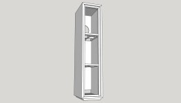
longest reliable / affordable narrow ribbons that can actually be purchased in us ?
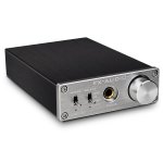
saw this Fountek 10i

1740636711597.png


and thought that would be great for line array but it doesn't seem to be sold anywhere.

the "fins" on top and bottom of founteks really would cause rather wide gaps in the line array so having a longer ribbon would mean fewer gaps and also hopefully lower cost because you don't have to pay for as many transformers ...

but i don't see any ribbons like this actually on sale ?

also would they be as durable / reliable as shorter ribbons ?

i am specifically interested in narrow 8mm wide ribbons as i want this as a supertweeter.

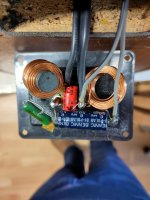
Inductor placement

Right now this is arranged in it's circuit so the components are as close to where they go next in series.

I'm wondering if I'd be better off putting the caps more in the center and all the inductors on the outside. Then I can run some wire underneath the plate to link parts where their leads are not long enough.

I understand the concept of inductor interference. I also understand having them in different planes eliminates most of that interference. That said, these inductors feel really close together

I want to keep it tightly packed for personal aesthetics. Both filters are mounting in the wall.

Attachments

  • PXL_20250227_014646487.jpg
    PXL_20250227_014646487.jpg
    445.5 KB · Views: 52
  • PXL_20250227_014638178.jpg
    PXL_20250227_014638178.jpg
    661.8 KB · Views: 52

Force cancelling concealed midwoofer

Hi guys, been a while since I've posted here. Got some iso acoustic isolation pods for my speakers and I was surprised how much of an effect it had on clarity all the way up into the midrange and it got me thinking. How much more resolution could I get out of a driver by using a second opposing driver for force cancellation. Its always been in the back of my head to try it. I had an idea but I'm not sure how effective it would be or what other problems would arise.

What if if I used a concealed driver inside of a sealed enclosure within the speaker (box within a box). I'm absolutely sure this is not a new idea of course. Is that because it doesn't do much? If I could calculate the rolloff of the interior driver due to high frequencies not passing through the box to the outside, if I ran them in series, presumably I could get some of the lower bass to fill in as well. I was thinking of using a driver like the SEAS CA22RNY H1471. If the second driver filled in the low end a little bit better maybe I could get away with using a 1st order crossover and then using a horn up above 1.3khz or so.

Just wondering if anyone has tried anything similar or if you know any preexisting designs that have done similar and how it sounded.
1740637784255.png

HE1000se and 45 based SET

I'm new here, thank you for allowing me to post. I have been using my HiFiman HE1000se with a MOJO2 to satisfaction but I also have a lovely SET tube amp that I think might bring some joy if I could hook up my headphones. The amp is a Gorden Rankin Bugle 45, 2W, SET. I do use a proper preamp (with no headphone jack) so I can adjust volume. Can I just wire up a 3.5mm socket to the output terminals of the SET?

Skar RP2000.1 issues

So I ripped every single 3205 out of this thing because they were all shorted.. I still have 350ish ohms between ground and power. Is that acceptable. ?All the outputs seem alright but I should remove all the rectifiers to power up with the new 3205s right? Sorry it's been a while.. hope to hear from you perry. I've got a new digital oscilloscope coming in the mail tomorrow.. all my belongings were stolen ...yes basically everything I owned was stolen I finally have a good station built again... I don't know how I got buy without a desoldering gun! This thing is the ****.... I'll re-read your tutorial can you please send me the link perry . Thanks
Projects by fanatics, for fanatics
Get answers and advice for everyone wanting to learn the art of audio.
Join the Community
507,783
Members
7,888,320
Messages

Filter

Forum Statistics

Threads
406,236
Messages
7,888,320
Members
507,783
Latest member
ys.zhu