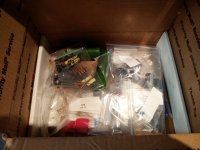
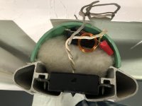
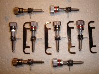
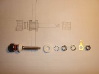
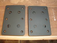
FS: GU50 tubes 4 pieces + sockets
SOLD
New never used.
Please send me PM to discuss price and postage.

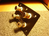
New never used.
Please send me PM to discuss price and postage.


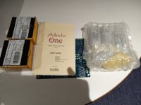
This book is essential reading principally for designers of linear audio frequency power amplifiers and more generally students and amateur enthusiasts of audio frequency electronics.
A first-principles analytical approach is here preferred because it engenders an intuitive appreciation of the workings of linear audio frequency power amplifiers, and it provides the engineer and researcher with a sound foundation for further work in the field.
Among other matters, the author cogently and succinctly
1. Evaluates the merits and demerits of two pole Miller minor negative feedback loop frequency compensation (TPMC) and localised two pole Miller minor negative feedback loop frequency compensation (LTPMC) and develops clear, systematic means by which these frequency compensation networks may be optimised.
2. Tenders two novel feedforward-compensated push-pull folded cascode transimpedance stage (TIS) designs in which slew asymmetry is banished.
3. Renders two novel feedforward-compensated push-pull transimpedance stage (TIS) designs based on the complementary emitter-coupled transistor pair of Sziklai et al.
4. Assesses the value of Burwen’s Inductive Frequency Compensation (IFC) in context.
5. Presents six idiosyncratic audio frequency power amplifier designs compensated with optimised LTPMC networks and incorporating non-invasive anti-saturation measures.
6. Examines monolithic/discrete composite linear audio frequency power amplifiers and their frequency compensation.
7. Describes how Safe Operating Area (SOA) protection networks may be correctly and accurately designed so that they remain inert when the amplifier does not require protection.
8. Gives an account of error feedback correction and presents three novel error feedback correction circuits.
9. Discusses output-stage-inclusive single pole Miller minor negative feedback loop frequency compensation (OSI-SPMC).
The author gives all credit to Almighty God, the fount of all knowledge and without whom nothing is possible, through His son, Jesus Christ.
Finally, the author hopes devoutly that adopters of this book will derive as much pleasure from reading it as he did from writing it.