Hi. Here I am again with my vintage amplifier copy.
Just when I thought that I was finally done something has to go wrong again...
I was working on the vintage amplifier that I copied from the old solid state radio. It is based around ac187k, ac188k complimentary pairs for the outputs and silicon transistors for all the other stages. I know it is not the best circuit (no thermal compensation or emitter resistors) but now I really want to finish it plus that circuit was in that old radio from the 70s and still works after rough conditions in the workshop of my grandparents.
Anyway. As I was finishing up the whole amplifier module it was working fine but one channel shorted the outputs without any overheating or anything strange. I just touched the input for "buzz test" and it shorted after 1 second.
The other channel works fine for now but I am scared of destroying another pair of transistors...
So here are my questions:
1 was maybe 16v too much for the circuit?
2 what is the maximal safe voltage?
3 can it be converted to silicon transistors?
4 why do you think the transistors failed (they were stone cold!!!)
I personally suspect that I damaged the transistor in previous attempts (I accidentally swapped emitters and collectors around) and it broke down.
This was supposed to be a fun project but it turned into frustration... But I want to finish it now because I want to understand what went wrong.
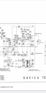
Here is the circuit diagram of the radio and some pictures...
Just when I thought that I was finally done something has to go wrong again...
I was working on the vintage amplifier that I copied from the old solid state radio. It is based around ac187k, ac188k complimentary pairs for the outputs and silicon transistors for all the other stages. I know it is not the best circuit (no thermal compensation or emitter resistors) but now I really want to finish it plus that circuit was in that old radio from the 70s and still works after rough conditions in the workshop of my grandparents.
Anyway. As I was finishing up the whole amplifier module it was working fine but one channel shorted the outputs without any overheating or anything strange. I just touched the input for "buzz test" and it shorted after 1 second.
The other channel works fine for now but I am scared of destroying another pair of transistors...
So here are my questions:
1 was maybe 16v too much for the circuit?
2 what is the maximal safe voltage?
3 can it be converted to silicon transistors?
4 why do you think the transistors failed (they were stone cold!!!)
I personally suspect that I damaged the transistor in previous attempts (I accidentally swapped emitters and collectors around) and it broke down.
This was supposed to be a fun project but it turned into frustration... But I want to finish it now because I want to understand what went wrong.
Here is the circuit diagram of the radio and some pictures...
Attachments
I notice that you already opened a thread about a similar but more recent Transiwatt 8 project: https://www.diyaudio.com/community/...ier-using-ac187-188-k-germanium-pairs.363963/.
Yours is a nice looking PCB and assembly for DIY with such old, germanium semis. Is it your own design? Anyway, down to the matter, I can see some problems with those delicate power transistors. The first that come to mind are a high supply voltage and inadequate protection - there is none that I can see. There is also no provision for setting bias current either so whatever bias current happens to flow according to the characteristics of the preceding semis, could easily be excessive and lead to rapid overheating and failure. You cannot tell just from the schematic, how the actual amp was assembled and component values may have been adjusted in production. You can't even expect the amp to work when using unknown sourced semis either - they may need to be selected on test. Since the AC187/188 transistor VCE maximum rating is only 15V, I'd agree with reducing the supply voltage to around 12V for safety - it makes sense, given your recurring problem. I think there is significantly more to the product than the schematic reveals.
The transistor devices themselves, are thermally coupled to their metal case with silicone grease. Even if the heatsink is huge, it could not prevent the germanium device from overheating and failing if the average current flowing was excessive compared to ratings. The grease is nowhere near as effective as directly bonding the device to its case, as with silicon power transistors, so we can't be too careful when setting up an amplifier and also checking that the bias current is safe. Whilst bias levels, if any, are much less than required for silicon transistors, there still needs to be enough for good sound quality and it has to be stable - not easy for DIY constructors who probably don't have appropriate design knowledge or experience.
4. searching for AC188K. datasheet found Vce 15V, Ic 2A and that could potentially explain why when you apply a buzz test which probably caused the output to go from "rail to rail" when one output transistor is saturated the other one receive (Colector - Emiter) the entire 16V - saturation voltage (could be like 16V - 0.2 V = 15.8V) therefore exceeding max Vce 15V
also
if the DC voltage without signal in emitters is 8V (half of 16V as it should be adjusted) then when one output transistor is saturated the maximum current is
I = U / R = (8V - saturation voltage) / 4 so in theory less than 2A.
However this is on the edge and any small variation in speaker (3.8 ohm instead of 4 ohm) or / and with an off adjustment of DC voltage in emitters (8.5 V instead of 8 V) or 6.8V as schematic says (that would be 9.2V colector emitter for the other transistor), will result in a instant Ic current higher than 2A for one of the transistors (and when one gets destroyed the other one follows).
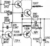
1. The original schematic might say 16V without signal. If the original supply transformer has for example a equivalent internal resistance of 0.6 ohm, then at 1.8A peak current trough transistors the voltage will drop to 14.92 V, less than 15V. Maybe you are using a 16V stabilized power source or you have better capacitors and your voltage stays 16V at peak current.
2. Based on datasheet maximum 15V. Want to be safe? stay below 14V; personally I think an AC188K amplifier with a 4 ohm speaker should be used with 12V
3. You can replace with silicon transistors (more crossover distortion than the ones with germanium if you make no other changes). If you hear the distortion try adding a diode (could be 1N4148) as attached (normally you should add more components like 0.22 ohm resistors in emitters, but one diode is rather simple and could work); do not use the attached diode schematic with the germanium transistors, do not start without transistors mounted on heat sink, one hand on the sink when you apply power and disconnect if you feel they start to overheat without signal.
Until you finish testing I recommend to use for example a 12V 1A electronic power source (which enters in protection mode and limit the output current if you exceed the rated 1A).
also
if the DC voltage without signal in emitters is 8V (half of 16V as it should be adjusted) then when one output transistor is saturated the maximum current is
I = U / R = (8V - saturation voltage) / 4 so in theory less than 2A.
However this is on the edge and any small variation in speaker (3.8 ohm instead of 4 ohm) or / and with an off adjustment of DC voltage in emitters (8.5 V instead of 8 V) or 6.8V as schematic says (that would be 9.2V colector emitter for the other transistor), will result in a instant Ic current higher than 2A for one of the transistors (and when one gets destroyed the other one follows).
1. The original schematic might say 16V without signal. If the original supply transformer has for example a equivalent internal resistance of 0.6 ohm, then at 1.8A peak current trough transistors the voltage will drop to 14.92 V, less than 15V. Maybe you are using a 16V stabilized power source or you have better capacitors and your voltage stays 16V at peak current.
2. Based on datasheet maximum 15V. Want to be safe? stay below 14V; personally I think an AC188K amplifier with a 4 ohm speaker should be used with 12V
3. You can replace with silicon transistors (more crossover distortion than the ones with germanium if you make no other changes). If you hear the distortion try adding a diode (could be 1N4148) as attached (normally you should add more components like 0.22 ohm resistors in emitters, but one diode is rather simple and could work); do not use the attached diode schematic with the germanium transistors, do not start without transistors mounted on heat sink, one hand on the sink when you apply power and disconnect if you feel they start to overheat without signal.
Until you finish testing I recommend to use for example a 12V 1A electronic power source (which enters in protection mode and limit the output current if you exceed the rated 1A).
Attachments
Last edited:
Class C amplifier (no bias). With a power supply of 16V and a load of 4 ohms, you received a current of 2A (maximum allowable). Try a 6-8 ohm load.
Vcer=18V Vcbo=25V according to the old databook (nearly thrown that out several times!).
With no AB bias this SHOULD allow for 16V as the off device will have a reverse base bias.
(Vceo=15V).
I would not run these on a PSU above 12V, even with the apparent max spec not being exceeded.
Also the datasheet indicates a min gain of 50 at 1A so worst case you won't get more than 1A (at least from the PNP (lower) output device.
Best case, you will, and that could cause the overload with 3 ohm speakers. Keep to 8 ohms (nominal, could be 6 as DIY says) and while you may only get 2W out, that would be my recommended max for these devices. Datasheet claims up to 3W but often such circuits suggested high impedance speakers (unusual 12 ohm or perhaps 15 ohm).
The “off” device doesn’t have much of a reverse bias - maybe two tenths - and that’s with a load. Don’t exceed VCEO. And Ge devices are ridiculously easy to make go into secondary breakdown. Go anywhere near full dissipation at half VCEO and bang.
Thanks guys. Really appreciate the help I get from this forum.
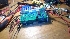
So first of all yes the pcb was designed by me (my first ever pcb) but I tried following the original component layout from the radio. As for the construction of the whole "module" with both boards and heatsink. That was my design. It involved a lot of cutting, drilling and tapping but it turned out pretty good.
I tested the other channel on 12v and it was perfectly happy, no problems at all.
Voltage of the output capacitor is around 6 volts so that seem fine to me.
I am powering it with my bench power supply so yeah it was probably too much for the little transistors since I did notice that in the original radio when I turn it up lights are dimming to the sound quiet a bit.
Also I have a 12v power transformer that I wanted to use but the problem is that after rectification and smoothing the idle voltage goes over 20v!!!
So is there a way to regulate the voltage without loosing a lot of power into heat or do I need to find some other power transformer?
Use a switching buck converter to regulate if you don’t want to live with the power loss. There are many single IC solutions on the market so all you need to do is follow the data sheet application schematic. Not any harder to use than a 7812, other than needing the LC filter at the output.
Lm317Thanks guys. Really appreciate the help I get from this forum.
So first of all yes the pcb was designed by me (my first ever pcb) but I tried following the original component layout from the radio. As for the construction of the whole "module" with both boards and heatsink. That was my design. It involved a lot of cutting, drilling and tapping but it turned out pretty good.
I tested the other channel on 12v and it was perfectly happy, no problems at all.
Voltage of the output capacitor is around 6 volts so that seem fine to me.
I am powering it with my bench power supply so yeah it was probably too much for the little transistors since I did notice that in the original radio when I turn it up lights are dimming to the sound quiet a bit.
Also I have a 12v power transformer that I wanted to use but the problem is that after rectification and smoothing the idle voltage goes over 20v!!!
So is there a way to regulate the voltage without loosing a lot of power into heat or do I need to find some other power transformer?
Wall transformers are sold by the rated dc voltage at the rated current. They go much higher in voltage at lower currents.
I'd try a 6 v wall transformer to see what the voltage is open circuit. Probably about 12 but may be higher. Don't go higher on this primitive circuit. There are reasons people ran away from germanium transistors, very hard.
I'd try a 6 v wall transformer to see what the voltage is open circuit. Probably about 12 but may be higher. Don't go higher on this primitive circuit. There are reasons people ran away from germanium transistors, very hard.
Yes I am starting to see how unreliable these germanium transistors really are. I already had some leaky ones in the old record player that I repaired...Wall transformers are sold by the rated dc voltage at the rated current. They go much higher in voltage at lower currents.
I'd try a 6 v wall transformer to see what the voltage is open circuit. Probably about 12 but may be higher. Don't go higher on this primitive circuit. There are reasons people ran away from germanium transistors, very hard.
Is there some protection circuit that would work on such a low power???The circuit has no output short circuit protection. Transistors can be damaged.
Most of the circuits I saw use some resistors for current sensing but I think on such a low power it would cause too much of a loss.
Anyway. As I was finishing up the whole amplifier module it was working fine but one channel shorted the outputs without any overheating or anything strange. I just touched the input for "buzz test" and it shorted after 1 second.
This maybe a hint: Your buzz test may have caused that amp to oscillate - often ending in desaster with such circuits.
This maybe a hint: Your buzz test may have caused that amp to oscillate - often ending in desaster with such circuits.
I thought about that too. But soon I will hopefully get myself an oscilloscope so I will be able to analyze the output of the amplifiers that are giving me issues.This maybe a hint: Your buzz test may have caused that amp to oscillate - often ending in desaster with such circuits.
Short answer😱scillation=death.
Motive?
Transistors are so slow that when lower one is turned OFF, it takes a looong time to disconnect, but upper one turns ON quickly.
Result?
Both are ON at the same time, across full supply output.
Exact same thing with the opposite polarity swing.
Combine that with low/nonexisting SOA and instant destruction.
Protection?
Forget it, any real working one will choke sound to death.
Personal experience: back in the day early-mid 70´s) I commercially made battery powered small Guitar amps, my "competition" to then famous US made Pignose amps.
Power transistor choice? AC187/188K
I made over 100 of them, they worked forever and a few are still in use, some were used in Recording Studio by some of our best Rock Stars, go figure, I am still asked for them over 45 years later.
How did I get them to work forever?: I fed them 9V from 6 "C" cells and loaded with a 3.2 ohm 6" speaker: well within ratings.
Hard clipping is also deadly for Germaniums, for the same reason, they "stick" against one rail ... and stay there for an appreciable length of time, while the other half already turns on.
No protection will protect you from that, so Designers simply didn´t allow transistors to EVER reach there.
Famous VOX amplifiers (Beatles - Rolling Stones - Status Quo - Queen -the Royal Family as Rock is concerned) incorporated what they called "the VOX Limiter", not what we would call it today but an adjustable clipper which was set up so drive signal was clipped so power transistors did NOT reach supply rails , missing it by a few Volts.
If really dedicated, you could add one to your own, it´s a simple circuit.
For a more complete explanation:
https://www.premierguitar.com/adjustable-clipping-in-vox-amps
http://www.voxshowroom.com/us/amp/watchdog.html
Thanks for all that useful information. That's really cool to hear that some little amps were used to record guitar in studios...Short answer😱scillation=death.
Motive?
Transistors are so slow that when lower one is turned OFF, it takes a looong time to disconnect, but upper one turns ON quickly.
Result?
Both are ON at the same time, across full supply output.
Exact same thing with the opposite polarity swing.
Combine that with low/nonexisting SOA and instant destruction.
Protection?
Forget it, any real working one will choke sound to death.
Personal experience: back in the day early-mid 70´s) I commercially made battery powered small Guitar amps, my "competition" to then famous US made Pignose amps.
Power transistor choice? AC187/188K
I made over 100 of them, they worked forever and a few are still in use, some were used in Recording Studio by some of our best Rock Stars, go figure, I am still asked for them over 45 years later.
How did I get them to work forever?: I fed them 9V from 6 "C" cells and loaded with a 3.2 ohm 6" speaker: well within ratings.
Hard clipping is also deadly for Germaniums, for the same reason, they "stick" against one rail ... and stay there for an appreciable length of time, while the other half already turns on.
No protection will protect you from that, so Designers simply didn´t allow transistors to EVER reach there.
Famous VOX amplifiers (Beatles - Rolling Stones - Status Quo - Queen -the Royal Family as Rock is concerned) incorporated what they called "the VOX Limiter", not what we would call it today but an adjustable clipper which was set up so drive signal was clipped so power transistors did NOT reach supply rails , missing it by a few Volts.
If really dedicated, you could add one to your own, it´s a simple circuit.
For a more complete explanation:
https://www.premierguitar.com/adjustable-clipping-in-vox-amps
http://www.voxshowroom.com/us/amp/watchdog.html
- Home
- Amplifiers
- Solid State
- My DIY amplifier blew output transistors, what has gone wrong?