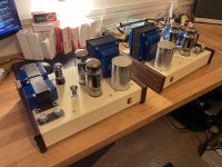
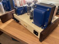
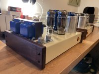
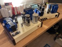
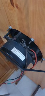
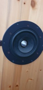
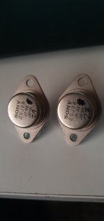
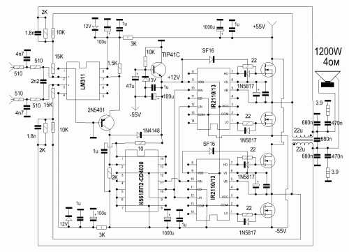
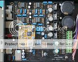
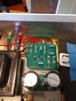
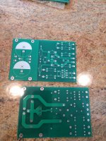
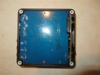
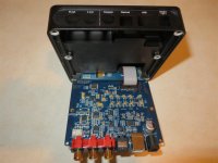
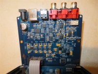
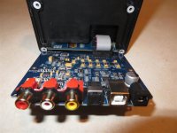
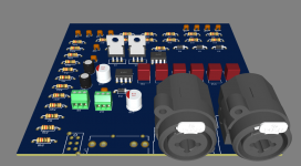
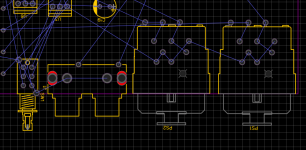
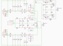
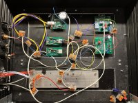
kondo m77 clone PCB stuffed and working

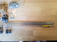
Hi, a friend of mine is selling his M77 clone PCB, it has all the phono and PSU modifications I talked about in this other thread https://www.diyaudio.com/community/...hone-preamp-clone-project.358732/post-6748859 , that means, the darlington heater regulator and the RIAA modifications. 4 tubes are included (as he only used the phono section). The line stage was tried and works, but, as said, only 4 tubes included. It comes with a low noise, potted toroid power transformer.

PM me if you are interested!

XLR Connection , how to connect the Pin 1

Hi Guys ,
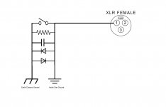
I want to use a XLR connection for my amps and I am confused how should I connect the Pin 1 & Case , should it go to audio ground or the chassis earth.
there is a earth loop breaker between chassis earth & audio ground with a switch which can bypass the earth loop breaker and in that case chassis earth and audio ground becomes same.


regards
Phoenix

Attachments

  • xlr connection.jpg
    xlr connection.jpg
    30.2 KB · Views: 259

[Infinitas]Freedsp infinitas over MCU board

Im studying freedsp Infinitas and I have doubts.
I checked this link
https://www.diyaudio.com/community/threads/infinitas-usb-audio-class-2-freedsp-32-in-32-out.330711/

I have this doubts because I havent a lot of equipment to do this .

Subject of doubts 1- Infinitas board


Could Infinitas board be builded over an MCU board like XK-EVK-XE216 ? Can I replace with an Arduino compatible board? What is the cheapest MCU for that?

Subject of doubts 2- Analog IO


Is there any MCU board that could be able to build the analog IO expansion boards? Are there any Arduino compatible ones?What is the cheapest MCU for that?

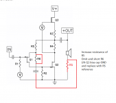
Improving the linearity of an N-ch MOSFET output stage

I am happy to invite forum members to have a look at my short article:

http://www.ant-audio.co.uk/Theory/N-channel D-MOSFET output stage with improved linearity.pdf

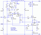
In this thread I will try to answer questions about that circuit configuration and also about the last diagram from the article - a practical example of an output stage that can be used with or without an overall NFB with either tube or solid-state VAS. I attach this circuit diagram here as well.

Alex Nikitin

Attachments

  • output_stage.gif
    output_stage.gif
    9.9 KB · Views: 3,869

Albums played once then played again years later and WOW!!!!

Roy Harper - HQ: ~35 years unplayed.
Duffy Power - Blues Power: ~15 years unplayed.

There are more, but these two really stood out for me as suddenly being really great, having been, at best meh, when I first heard them. I couldn't cope with the Duffy Power album at all and really did only listen to it once. I had another go and really liked it and was sad to find he died in 2014. But I got a copy of 'Tigers' and thought it was rather fine and will be buying some more, though I'm sad I'm not putting money into his pocket.

With Harper I fell in love with Bullinamingvase at first listen, bought a lot of his LPs but never liked anything else as much. I've been digitising my LPs and got to the Rs and low it turns out I REALLY LIKE Roy Harper. All that stuff that seemed like lifeless out of tune self indulgent nonsense has turned out to be rather thoughtful and full of heart.

Was I a blind fool once or am I a sentimental old man now? God knows, but I still like the stuff I liked before, and if there's even more music to enjoy I'm all in favour of that. Particularly if I already own it 🙂

Experience With Vintage Magnavox?

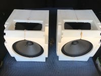
I rescued these from a cabinet at the curb in my neighborhood. 10"-11" woofer and horn tweeter in a sealed foam enclosure with an XO consisting of inductor, cap, and resistor. In great condition. Try drivers individually with real XO? Ported or sealed? Want to find out any info before I bust into the cab. Hoping Planet 10 Hifi will chime in. Thanks for any suggestions.

Attachments

  • IMG_0285.jpg
    IMG_0285.jpg
    387.8 KB · Views: 341

2n4102 SCR replacement??

I am repairing a HP 6209B power supply and it uses a 2N4102 600V 2amp SCR as a pre-regulator. I need to replace the part and I found Digikey has only ONE 600v 2A SCR listed. Looking at the datasheet for the 2N4102 and looking at Digikey S6002ESRPCT-ND looks to be as close of a match as I can find. Please take a look at let me know what you think? Is this a good replacement part?? if not, what spec did i not look at?

Attachments

QUAD 306 distortion on left channel

Hello, I'm new on this forum. As I have read another thread relative to the Quad 306, I told to myself that I could perhaps find some help here.
So, my 306 shows a strong distortion on left channel as soon as the level is not at minimum.
When used with a Quad 34 preamp, the sound is strongly distorted, on the left channel only, as soon as the volume knob is over 1 or 2. The right channel is ok.
The seller told me that the amp was never serviced since he bought it new in the 80's.
The first thing I did was replacing the four 4700μF electrolytic capacitors, but that didn't change the problem.
I measured every tension noted on the schematic, and nothing seems abnormal. You can read the values on the attached picture.
So now, I wonder where to investigate?
Thanks in advance for your advices. And sorry for English is not my language.
IMG_20220330_210423~2.jpg

WinISD reliability for 6th-order bandpass enclosures?

Hi, all...

I'm considering building my first 6th-order bandpass. I've heard consistently that these are 'tricky' to get right, so I'm a bit apprehensive.

I have WinISD and am familiar with the program. It does calculations for 6th orders... but not quite as it does for the other enclosure types. As many of you know, it doesn't give you any kind of starting point for air space (although it does recommend vent length when you input those values)--you have to manually enter values and 'see what happens' on the response curve.

So, I was wondering...

Has anyone ever constructed a 6th order (based on WinISD numbers) and tested its frequency response? Did it match up well? Would you feel comfortable using WinISD numbers here?

P. S. I know many of you will recommend Hornresp, but I can't download it... so, really... just wanting to focus on WinISD accuracy.

THANK YOUI!

Fault finding - loud pop and 120hz noise instead of music

I've enjoyed this amp for quite some time now, but it developed a problem I'm trying to track down: https://www.diyaudio.com/community/threads/6v6-pp-ul-bias-point.360543/post-6359252

Symptoms? Loud pop and low level 120hz hum (no more music) in one channel. Happened the first time when I was playing white noise for speaker testing. Then another trouble free month. It now does it half of the time, the other half playing flawlessly. Also when powering up I experienced a few times the pop + a complex noise getting very loud while the tubes are heating, leading me to power off before killing my speaker.

I measured most of the components (power off, seems fine), swapped tubes (no cigar) and measured with power on (probably in bad-mode at that time: voltages were way off in one channel).

Before I do a systematic check of voltages in the bad channel, out of curiosity: is this oscillation? A bad solder contact? What baffles me is that it either works, either not, but the latter is steadily taking over.

Cheers
Simon

Lenco NSC complete - No trans

Hi, A little while ago I tried to swap this board for a mono cart. Now I have found the cart so it is offered for sale US$250 + postage (P?P OK to F&F)
(estimated around US$70 - US$90 tracked, or cheaper none tracked) Will be sent labeled for repair which may help with any taxes that sometimes get applied.

Cheers Derek

Attachments

  • 1125201522.jpg
    1125201522.jpg
    558 KB · Views: 143

SissySIT R.3 - kit packages

Presenting thread here: SissySIT R.3


Schematic and pcb screenshot post #1 , plenty of pictures after .

Tips and Tricks thread - will open, sooner or later

Reading entire thread is advisable , same as inquiring any technical question there : Be sure that you are aware of all things electrical and mechanical !

THF51-S still available on fleabay , watanabetomoaki confirmed seller , also pras1701 - being member here

instead , 2SK182, 2SK180; anyway, everything in linked thread

Pcbs are made for UMS , mounting directly to heatsink


Do not hurry - read , think , ask and only when you feel that you want it and can make it , proceed ...... advice which I'm finding applicable on practically anything .

For anything else , write either here , send PM or directly to >zenmodiyaudio@gmail.com<

Prices are mostly dictated with small scale nature of operation (as always is case) and time/work involved in matching and soldering little buggers.

For ordering , contact me at above written e-mail addy .


Kit options :

Option 1.
- LCH pcb ,
- RCH pcb ,
- all smd buffer JFets (Toshiba 2SK2145BL) presoldered ,
- smd precision CCS chips presoldered
- all smd caps and resistors presoldered ,
- 4pcs of 1uF MKC caps (for important bypass positions) enclosed.

Full price , including Paypal fee and P&P for registered shipping all around the Globe - 135E

Option 2.
- LCH pcb ,
- RCH pcb ,
- all smd buffer JFets (Toshiba 2SK2145BL) presoldered ,
- smd precision CCS chips presoldered
- all smd caps and resistors presoldered ,
- 4pcs of 1uF MKC caps (for important bypass positions) enclosed.
-all multiturn trimpots
-output P channel mosfets , 2 pcs , IRFP9140
-cascode bjts
-optocouplers
-all electrolytic caps (all Panasonics ,except Elna Silmic II for one signal route position)
-one-pin sockets for special resistor positions
-all (MF 600mW) resistors
-T0220 heatsinks - 6 pcs
-etc.

to recapitulate - everything what goes on pcbs , excluding signal xformers and pcb/mosfet mounting screws/nuts/washers and , of course , excluding THF51-S

Full price , including Paypal fee and P&P for registered shipping all around the Globe - 185E


If I have everything in drawers in moment of order , can ship in a week time;
If I don't have any of normal parts in drawer , shipping could be delayed up to 3 days;
If I don't have pcbs in drawer , shipping could be delayed up to 2 weeks;
If I don't have most critical part for getting in my neck of wood - CCS precision chips , shipping could be delayed up to 3 weeks.
All in all - you all know that ZM is slow, but inevitable :rofl:

Handy Addendum (in short : HA!):

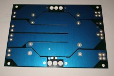
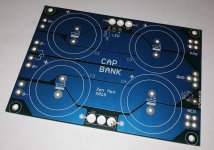
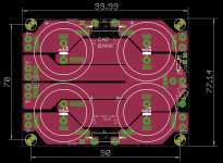
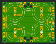
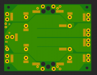
-Cap Bank pcbs - set of 2pcs; dual rail, CRC (pads, if you want differential CLC), snap-in up to 35mm Dia, resistor and pads for LED, position for 10mm NTC connecting Audio GND to chassis;
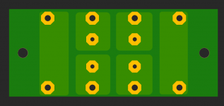
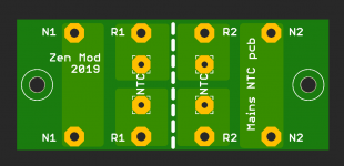
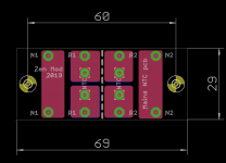
-NTC pcb/ FW style Soft Start - set of 2pcs; each having place for 2 independent NTCs;depending of arrangement of primaries of Donuts you're using. you'll need either one pcb for two Donuts, or one pcb per Donut

HA! set is 25E more

see pics for HA!; lazy to search do I have photo of NTC pcb, but who cares
Attachments

  • PSU pcb bottom.jpg
    PSU pcb bottom.jpg
    58.1 KB · Views: 1,376
  • PSU pcb top.jpg
    PSU pcb top.jpg
    86.1 KB · Views: 1,414
  • top eagle sshot.png
    top eagle sshot.png
    54 KB · Views: 1,400
  • bottom render.png
    bottom render.png
    18.5 KB · Views: 1,361
  • top render.png
    top render.png
    38.4 KB · Views: 1,353
  • eagle sshot.png
    eagle sshot.png
    17.4 KB · Views: 413
  • CB top render.png
    CB top render.png
    160.1 KB · Views: 466
  • CB bottom render.png
    CB bottom render.png
    88.7 KB · Views: 426

Finally done…for now, mirrored SSE pair

So after loving my original SSE for a couple of years I kept eyeing my 2 way horn speakers that use active crossovers and wished I had four channels of single ended tube to drive them. With the amount of times I tinkered with my original SSE I was very comfortable with it and figured I’d just make another one and they could live together with the horns.

First issue was my original used 5k/8 OPTs and the woofers in the horns are 4ohm, that was pretty simple to get around, just ordered a pair of matching 5k/4’s along with another xpwr222 from edcor.

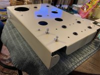
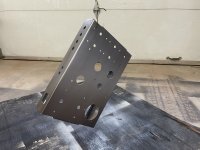
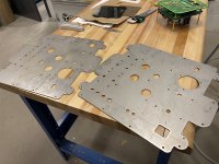
That sorted, then came battling with my internal need for symmetry and aesthetics, so I spent probably a bit too much time figuring out the smallest possible footprint where I could reasonably mirror the chassis and settled on what’s shown below. The choke is horizontal underneath the PT as the feedback from folks on here a few months ago was to keep it as far from the OPTs as possible. Used a water jet to cut the panels and used simple bends and walnut caps to tidy things up. Finally a pair of mono pots so each driver could be tweaked once it’s set up.

I’m super happy with how they turned out, it was my first endeavour with sheet metal based cad so it was a learning experience that thankfully worked out.

Now I just finished putting them together and it’s too late to hook them up, so listening impressions tomorrow.

Attachments

  • B7DF6D81-231A-47A6-9D4A-33CB3B20AC12.jpeg
    B7DF6D81-231A-47A6-9D4A-33CB3B20AC12.jpeg
    510.3 KB · Views: 176
  • E7390011-83A4-44B7-9185-A53F203D5249.jpeg
    E7390011-83A4-44B7-9185-A53F203D5249.jpeg
    447.3 KB · Views: 172
  • F97CC99E-5258-47C9-861C-410C3DF1958C.jpeg
    F97CC99E-5258-47C9-861C-410C3DF1958C.jpeg
    405.5 KB · Views: 149
  • 57F11DBC-719A-48EF-BEFC-D6D77C14E328.jpeg
    57F11DBC-719A-48EF-BEFC-D6D77C14E328.jpeg
    506.1 KB · Views: 153
  • C63C37C5-76A7-42C8-AF20-CE6FF1200563.jpeg
    C63C37C5-76A7-42C8-AF20-CE6FF1200563.jpeg
    414.2 KB · Views: 155
  • 32311069-24C1-4DC2-AA3A-7A5B08DF43BD.jpeg
    32311069-24C1-4DC2-AA3A-7A5B08DF43BD.jpeg
    538.6 KB · Views: 155
  • 2BE0F0D6-DDDC-429B-AE11-94B56FA9C27F.jpeg
    2BE0F0D6-DDDC-429B-AE11-94B56FA9C27F.jpeg
    475 KB · Views: 168

The "AmpDuino" project

Since I finally realised that even I could probably benefit from incorporating a little bit of software in my otherwise purely hardware-based projects, I have been toying with the idea of building a more generic controller that could be used for many different audio projects. Obviously this is very much inspired by the LCDuino, The HiFiDuino and other similar projects, but I have tried to give it my own flavour anyway 🙂

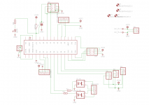
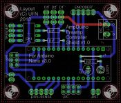
The AmpDuino is a dedicated shield for an Arduino Nano v3 board. It incorporates most of the connections that would be necessary for audio-based projects while hopefully being expandable enough to be used for other things as well. The standard "breakouts" available are:

- Two I2C connections (for display and one spare)
- Dedicated port for rotary encoder w/ push button.
- Two "trigger" outputs designed to be isolated via a PC827 optocoupler (which is of course optional)
- Three "general purpose" digital inputs/outputs (for IR receiver, IR transmitter or similar)
- Dedicated ports for interfacing with a motor driver for volume pots and sensing the position of the pot (shamelessly copied from the LCDuino…)
- SPI port for controlling DACs or PGA23xx type devices
- Power LED (if there is no Arduino mounted to indicate power)
- Reset terminal broken out to connector (although the Nano onboard RST can be used as well)
- 5VDC input with a another smaller connector that can be used for output.

The board measures 1.95"x2.3" and is two layers.
I wanted this to be as compact as possible, but I have also deliberately based this on the Arduino nano instead of just the microcontroller on its own. The Nano boards are very cheap and having a "complete" Arduino available should make tinkering and tweaking much easier than having to mess with in-circuit programming etc. (ok, this may just be my irrational fears at play here 😉)

I have deliberately moved away from the LCDuino form factor, because a "normal" board can be positioned in many different enclosures. Using I2C for the display driver gives more options than just a standard 16x2 LCD. The I2C display connection also makes it possible to get rid of the port expander and still have enough digital pins for most applications (I think).
Discarded ideas:
- Onboard PSU (not really enough space, probably easier to add an external regulator depending what voltages are available already and how much current is needed)
- Dedicated port for IR sensor (could be done, but he current D1-D3 ports are more usable and will allow other usages as well (real-time clock etc.))
- Onboard components for the IR receiver. Could be done, but would mean the sensor would have to be mounted closer to the board, so probably easier done with an expansion module which has the sensor and the external components on the same board.
- Onboard SSR for power connections: Could be done (with something like a Sharp S202), but again it is more versatile if kept offboard.
- Onboard motor driver for volume pots: Not really enough space and would not always be needed. Instead, I have retained the basic connections and I am working on a dedicated board that can be soldered straight to the terminals of the motor on Alps pots (or at least that's the plan)
- Real time clock: This is obviously a very nifty feature in the LCDuino, but I can't see myself using it in many applications.
- Input selection: This is a tricky one, but initially I'll keep it offboard. Anyway, for relay-based selection you can always "cheat" and send pulses to a 4017 instead. (hmm, probably should make a breakout board for this one…)

Any comments/suggestions? Is this a lousy idea? 😀

Attachments

  • Schematic v5.png
    Schematic v5.png
    27.6 KB · Views: 1,011
  • Board v5.png
    Board v5.png
    82.4 KB · Views: 981
  • Ampduino-5.GTO.png
    Ampduino-5.GTO.png
    39.2 KB · Views: 964

Advice For Old College Capstone Project

IMG_20180501_162918.jpg

Please ignore the mess, and the bottom-left pot did nothing.

What a mess! I didn't have enough time to learn kiCAD nor enough money to have it properly printed at the time, but as a proof of concept, it worked. I was digging through my old hard drive and I came across my old college capstone project. It's been a while since I had a chance to look at it, so I'm wondering if anyone could point out things I could do to improve on it.
CAPSTONE PROJECT.jpg

I named it the amplifizer since it's comprised of a preamp, EQ, and a headamp. The concept was that you could power it off a single-rail +5V 250mA USB port, plug an audio source into it, and have fun! I used the Wurth Electronik WE-EPLE USB connector since it had an integrated EMC filter, the Semtech SC632A helped normalize a constant 5V flow, and the TI LM2663 gave me a -5V rail to have more flexibility with dual-supply op amps given my power constraints.
IMG_20180501_200452.jpg

I don't remember why I went with a cascading TI OPA1644 preamp design as it's probably overkill for something like this. I used the TI OPA4376 for my EQ bands, and Analog Devices AD8655 in class-A to drive my headphones. The TI TLE2426 was a simple virtual ground solution that just worked. As you can probably tell, I'm a novice coming back to this, but I thought it would be cool to revisit and hopefully improve after all these years later. Any questions or advice would be greatly appreciated. Thank you for your time!

Bridging tweeter with two stereo exciters

Hi all,

I am building a speaker using two Dayton 8 ohm 10 watt exciters and an 8 ohm tweeter. It is being powered by a 2.1 amplifier with dsp (Arylic). I currently have the tweeter and exciters in two different channels and am running in mono, the tweeter has one capacitor. I am wondering if it is possible to run the two exciters in stereo, and bridge the tweeter so that it is in mono? The amplifier does not state the impedance range, for sure 4 ohm but I am not sure how it will do with below that, others say it is fine but not positive.

Looking for Full Range for mid in Open Baffle

Hi,

I am looking for a full range driver to use as a midrange in a 3 way open baffle.

All the best - most lifelike and dynamic - drivers I have heard have been full ranges like Lowther, Coral, Fostex, etc.

Can anyone suggest a driver that would make a great mid range ( 250 - 2k+) without having to cut of wizzer cones etc?

What are the Supravox and PHY drivers like (never seen or heard these)?

I bought Seas Exotic W8's, hoping that they would do what I want, but so far I am disappointed - they sound quite flat 🙁. I will continue to run them in, but I suspect that I need to find an alternative.

Thanks

David


Background information on my project:

I am building a 3 way partially open baffle system. The most important things for me is to have life (energy/dynamics), timing (PRAT), and balance.

I was (for about 7 years) using a pair of reworked Alon Phalanxs, and did really like the openness that the open baffle gave to the midrange and top end. The things that I was less enthusiastic about in these speakers were the complexity of the 4 way design and getting the drivers to integrate, the metal dome tweeter, and the relative inefficiency. I have been listening a lot to light paper cone speakers (Lowthers and Coral Beta 8s) in other setups, and have been very impressed with the life and dynamics.

To that end, I decided to do a high efficiency semi open baffle speaker, with a light paper cone midrange, and tweeter mounted in a panel, and a bass in a vented box underneath, with an average efficiency of 94db.


I have bought the following drivers:

Seas Exotic T35 and W8, tweeter and mid

Seas Exotic T35 Tweeter

Seas Exotic W8 Woofer

Here are a couple of pictures:

An externally hosted image should be here but it was not working when we last tested it.


An externally hosted image should be here but it was not working when we last tested it.


Crossovers to be at 250Hz and 2K, very simple first order. The W8 also offered the possibility of running it with no lower filter due to it's high xmax.

The 15' bass drivers that will be in a 140L box will be these:

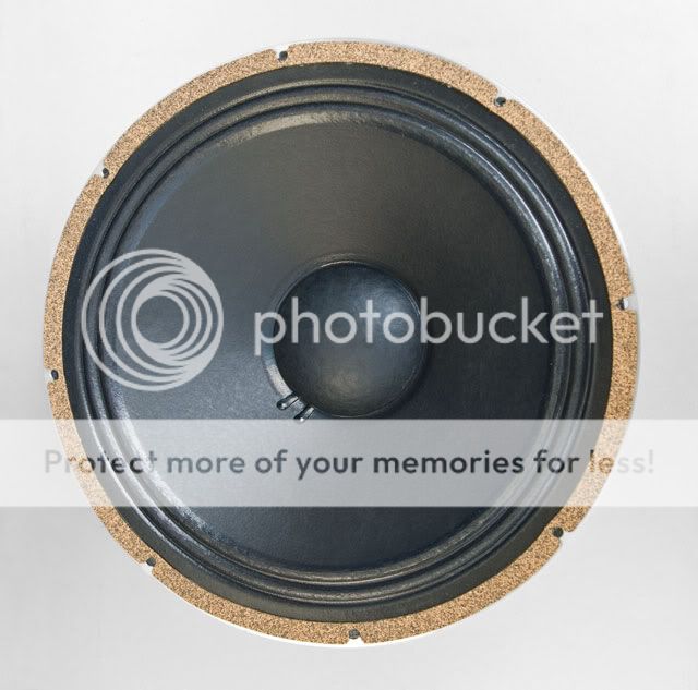
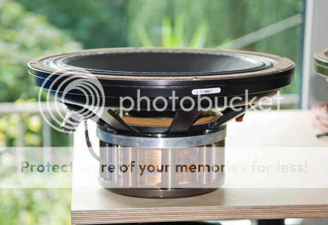
Kilimanjaro Field Coil 150VWLs

a150wvl_dsc0003.jpg


a150wvl_dsc0018.jpg


They are essentially JBL K145 field coils.

So far I have been testing, measuring and listening to the the drivers. The T35 sounds fantastic, but I am less impressed with the W8 which does not have the life that I hoped for.

RPi3 B+ wifi and USB

ok so i have not been active for a while and stopped playing with my PI.

i have a question for those more knowledgable.

if i use my Pi3 with a large Micro SD card as storage for music files with Mo0de as the headless player over wifi will the USB ports suffer from the Ethernet problems when i plug my DAC in. i will only be using local storage via the Micro SD.

also, i personally dont see a problem with jitter from the usb if the dac has built in filters/clocks so i see no need for a top hat dac but please correct me if i'm wrong.

Orion XTR2500.1Dz Over Current Circuit problem?

After waiting almost a month for parts I finally have full on switching everywhere it needs to be, all the way to output FETs, everything looks nice and clean, couldn’t be happier. I install Output FETs and amp now cycles in and out of protect.

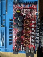
Original problem was blown Power Supply FETs, taking out the 072 & 2110 on Output Riser card. I replaced all. Amp powers up perfect without Output FETs in, idles @ 1A, but with Output FETs installed it boots as follows:

PSU goes into CC mode while building rail voltage (same wether limited to 3A or 10A) until about -60Volts is built up, then I hear some kind of click near output section, current pull drops to a few mA, rail voltage drops to about -15V, and process restarts, cycling like that.

I haven’t let it cycle more then a few times, not trying to damage anything, I am being way over cautious though because of how long I had to wait on parts. I’m not to familiar with over current circuits, this is the 1st I will be working on actually. I’m assuming that is the problem.

I’ve reflowed the Over current protection rails just in case, don’t know the next step from here, hoping to have some advise on some direction.

Thank you 🖖🏼 Posted a few pics of each of the sections waves just cause. Looks like rail voltage builds up to about -95/-100 volts on this amp I think. My Scope is off by about 5/7.5 in the 50v/100v /div range

Attachments

  • image.jpg
    image.jpg
    686.6 KB · Views: 247

Can ma12070 (pbtl mode) use single ended input mode

I use ma12070 to make an audio amplifier and use pbtl mode. Normal operation after power on.
But when I configured the input mode to single ended RCA input, the speaker made a lot of noise. I changed the grounding mode, and the problem remains the same.

I wonder if it is wrong to configure the single ended input mode as shown in the figure below in pbtl mode?

11.gif

Converting Verastarr SSA-644 to 240v

I just moved to Germany and want to configure my two Verastarr amps for 220-230v. I have an SSA-644 (same internally as the SSA-64) with a handwritten schematic for a 64, but its not very clear and some annotations are obscured, but apparently its straightforward. I beleive the OEM manufacturer for Verastarr was Cinepro who were then acquired by AB International after the untimely passing of the founder. Bob at AB International is no longer responding to queries (possibly as that company too is defunct.... URL no longer active).

Login to view embedded media
There are two unused wires on the toroidal transformer that I assume get connected to the junction box with the black circular ICL component.

Login to view embedded media
All spade pins are used for 220v vs 110v operation. This is how my SSA-644 is setup for 110v. Can anyone provide some guidance as to how the wires should be connected going from 110v to 220v?

Login to view embedded media
Thanks in advance

For Sale SAL08C08 in perfect state

Hi all. I sell my SAL08C08 pair. These are in perfect state with very light use and always with very low power amp (SE Vfet or elekit TU8200). Original boxes.
I add free one pair of 2SJ28 JA33 that I lost some time ago.
Price: 800 eur + paypal fees + shipping cost

Attachments

  • SAL1.jpg
    SAL1.jpg
    178.5 KB · Views: 147
  • SAl2.jpg
    SAl2.jpg
    162.8 KB · Views: 135
  • GIFT.jpg
    GIFT.jpg
    144.7 KB · Views: 123

Need help JVC XL-V 131 Schematic

hello friends,
I have a JVC XL-V131 and tried to build a new fetbased output-amp instead of the opamp-section. First attempt was very successful but then I made a fault and killed something. Now there is no more voltage in the dac/output section. I tried to fix it, but I have no schematic for it. Does anybody have a schematic for this player? I can`t find any in the net.

Hello All

I plan on a pile of questions so it seem only polite to offer and introduction and thankyou in advance.

I am a locomotive engineer. About now I wish that was electrical engineer. I'll give myself credit as being fairly good with mechanical things, but electrical, I just never too the initiative to learn. As I get older it becomes clearer to me how an early education is hard to replace if only because it instills the basics and teaches you to use a framework to answer questions and organize the way you think. I actually studied Finance and English. Sorry to say I wasted that money. I worked for Merrill Lynch for 6 years out of college and decided it wasn't for me. My other main interests are hunting occasionally, I'm an inactive private pilot because I just can't stomach the expense, and motorcycles. I have 2 Moto Guzzis, 2 BMW and 2 Suzuki.

Anyway, I have always enjoyed music and usually had the best of, what in hindsight, was a bunch of pretty bad systems back through the 90's. I guess at least they had plugs and wires as opposed to a phone and Bluetooth speaker as we see so often now.

I recently bought a small Tube Headphone/Preamp and 2 Adcom amplifiers. I enjoyed that enough so that within a couple of months am trying, aggressively, to learn and to build some decent projects on a budget. I built some kit speakers, put together a small speaker kit, built an Elekit TU-8500 and have been collecting some parts and kits that interest me. I bought a B1 Korg Nutube kit, some Honey Badger boards and F6 boards. I also bought the makings for a small chip amp from a company called Neurochrome. Neurochrome is not cheap but I appreciate the fact that the owner is very helpful and responsive. He, by all appearances, seems to be looking to perfect his products and they seem to be quality. I certainly don't mind paying extra to someone that will speak to me and will not sell me fakes or junk. Of course I really appreciate the DIY store. Seems ultra reasonable and is connected to this site.

I will be attacking the Nutube and F6 first. I think the F6 first because the parts count is low and, sadly, all parts seem to be in short supply. Neurochrome makes it very easy by providing a link to a BOM at Mouser and a lot of parts for that chip amp are backordered.

That's my best stab at a self portrait without going on and on. Nothing worse than listening to someone talk about themselves.

Drowning in parts. Please help

Hello.
I really need to clean out some of my parts, so I will sell everything cheap.
I just started the process today, and much more will come, and I will write which parts they are and manufacturer and parts count.
I hope its possible to make out my writing on photos, otherwise ask.
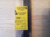
First up is a stick of IR irfp9240, 25 pieces unused, asking 30 us dollar?

Attachments

  • 20210729_203336.jpg
    20210729_203336.jpg
    1,013.9 KB · Views: 931
  • 20210729_203515.jpg
    20210729_203515.jpg
    709.3 KB · Views: 908
  • 20210729_203531.jpg
    20210729_203531.jpg
    639.9 KB · Views: 885

What to do with Kappa 15a? K15, Karlsonator or 115BK?

Ok, after solving my dilemmas with 511b horn (ordered PSD2002), I now struggle what to do with bass enclosure for my 2way with Eminence Kappa 15a. I initially thought to either do BR or shorter TL, which now seems to easy, because I have done it before. Since I haven't read diyaudio for 10 years or do, I discovered all those enclosures as XKi, Karlsonator, T15.... I would definitely like to try K aperture. Size is not an issue. I would like it to be wide as 511b horn, which is ~60cm.
So, after few days od reading it seems that Kappa 15a in regular K15 is safe bet?
Or should I resize Karlsonator to get desired width?

Post amplification signal boost in crossover instead of L-Pad??

Extract: Can I incorporate a simple amplification circuit in a HF crossover to boost a tweeter a few db to match the sensitivity of a compression driver mid instead of using an Lpad on the compression driver mid to match the sensitivity of the tweeter?

Hi I'm building/experimenting with a two and three way bi amplified system incorporating active and passive crossovers. I'm using a MiniDSP Dac sending an active crossover signal to a Ncore amp feeding a 15" woofer. That same dac feeds a tube amp powering a compression driver which covers the upper registers.

I'm interested in enhancing the treble by adding a tweeter (bullet tweeter, 1" cd, etc.). I would prefer to keep things simple and incorporate a passive crossover if possible. That said the compression driver mid (in a three way configuration) is anywhere from 3-8db more efficient than the tweeter I would be using. I'm curious if instead of using an L-Pad on the mid compression driver...

Can I incorporate a simple amplification circuit in a HF crossover to boost the tweeter a few db to match the sensitivity of the compression driver mid? If so what is a product that you recommend? The simpler the better -- something like this is ideal assuming it's not to crappy: https://www.htd.com/LGB-1.

Thanks.

  • Locked
Dynaco Mark VI

Dynaco Mark VI help needed by a newcomer to tube amps.
Does anyone have information on converting the Dynaco Mark VI to say a kt88 or something better?
My goal is to replace the discontinued 8417 to something with the same power or better that is still in production today. I would also like to keep them at 120 watts or better. Any information would be greatly appreciated.
Thank you

Adapting snap-In capacitors to vintage lead spacing?

Capacitors form factors change over time, and I have a 1989 Carver amp that needs new PS capacitors. Hole spacing on the PCB is 1/2" or 12.7mm, while snap-in capacitors are standardized at 10mm. It appears that the PS capacitors with the best specs are mostly snap-in these days like Nichicon LKG.

Is it workable to bend snap-in capacitor leads down and then back up at a slightly wider spacing, or will this make a mess? The traces on this PCB are such that moving the hole spacing is not an option.

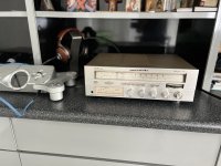
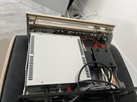
Marantz DIY hi end sreamer

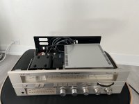
Needed to consolidate and clean up my optical rendu steaming solution . 3 boxes , multiple cables and such …
It looms awesome and no more wires all over the place .
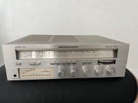
I will be working on crating DC cables ( 10 inch Mindorf Siver Gold.
I’ve replaced bottom plate with quarter inch aluminum that sits on top of 3 isoacustic isolators
after 24 hours no heat issues LPS is battery warm, optical rendu is little but warm but that how they run on the warmer side .
… I love how it looks , vantage look one of the best LPS on the market and optical rendu with optical media concer

Attachments

  • 5CFAC916-9326-408C-9A83-EBFBF93B0BD7.jpeg
    5CFAC916-9326-408C-9A83-EBFBF93B0BD7.jpeg
    397.5 KB · Views: 140
  • BBA1E4D9-196E-43B5-BCBC-8FE6F9FEB96F.jpeg
    BBA1E4D9-196E-43B5-BCBC-8FE6F9FEB96F.jpeg
    405.8 KB · Views: 128
  • 5A080C71-6258-4E89-9641-127123D52931.jpeg
    5A080C71-6258-4E89-9641-127123D52931.jpeg
    344.3 KB · Views: 115
  • 465C5661-83B4-4C83-A254-8F3C67D66AE0.jpeg
    465C5661-83B4-4C83-A254-8F3C67D66AE0.jpeg
    381.7 KB · Views: 126
  • 1C471D42-9E14-4B23-AFD9-9FC3F76EF12C.jpeg
    1C471D42-9E14-4B23-AFD9-9FC3F76EF12C.jpeg
    336.6 KB · Views: 139
  • 5CE32C76-4151-46DD-BB94-F17F241CB66B.jpeg
    5CE32C76-4151-46DD-BB94-F17F241CB66B.jpeg
    369.9 KB · Views: 124

Sealed Enclosure with a 'Twist' - Any Problems?

Hello, Forum!

I'm building a sealed enclosure for two 12s, which will be directed toward the rear of a hatchback (about 24" from the back). That's really not relevant to the question, but in case it comes up. So, here's the question:

Any problems/considerations with facing the drivers toward each other in a 90-degree angle (as shown below)?

It's really just two sealed enclosures facing each other (even though it looks 'bandpassy'). I wanted to do something a little sexier than a 'standard' mounting on the baffle, but I've never done it before (although I've seen it done) and wanted to see if people smarter than I saw something I didn't (that's you all!). lol

Thanks for the help!

untitled.png

FREE - SB26ADC-C000-4 + SB17NAC35-8 Floorstanding Loudspeaker - pick up only Newcastle NSW AU

GONE

I need to find a home for these speakers using highly regarded SB Acoustics Aluminium drivers SB26ADC-C000-4 and SB17NAC35-8. I'll be sorry to see them go as I really enjoy their sound and presentation which is a bit forward of neutral but I can't keep them. Pick up only Newcastle NSW AU. If you want to give me a few dollars for them, that's fine but is not a condition.

Some info:
18 litres, F3=38Hz
Cabinet with angled bottom divider and P2P brace with removeable back panel
Finished in white oak timber veneer
AR Series crossover uses Mundorf M-Cap capacitors and Jantzen inductors with crossover around 2300Hz
SPL 84dB and I used them with a Arcam FMJ-A19 (50W) and a 3886DR (32W) in a 4.2m x 5.7m room
A 8 ohm speaker with a minimum impedance of 6.26 ohm with a flat impedance plot within a few ohm
Designed to have a space of 250mm - 300mm behind the speaker from the back wall (only small amount of BSC)
The grille looks fine but a bit messy at the back as the fabric is stapled on but you don't see that

Ignore the black strip in some pics as it's a result of the camera flash.

Attachments

  • RZ_RZ6A.jpg
    RZ_RZ6A.jpg
    307.4 KB · Views: 190
  • RZ_RZ6A_drivers.jpg
    RZ_RZ6A_drivers.jpg
    522 KB · Views: 185
  • RZ_RZ6A_grille.jpg
    RZ_RZ6A_grille.jpg
    159.6 KB · Views: 172
  • RZ_RZ6A_back.jpg
    RZ_RZ6A_back.jpg
    266 KB · Views: 175
  • Like
Reactions: smms73

WEILIANG DAC5 - WM8741 & Tenor TE7022

I recently bought a WEILIANG DAC5 from China.


It sounds quite nice to me, but I expected better-looking square wave outputs from the MFSL test CD square wave tracks. I used a Win7-64bit machine and standard Windows drivers to drive the USB input to the Tenor TE7022 board, which, in turn, I think, drives the DAC5 via I2S.

1 KHz square wave as seen on my old 100MHZ Tektronix 454 scope at the phono connector output:


and 5KHz square wave:


I've never played with DACs before, but I think there must be some problems with this DAC. Can anyone with more familiarity with DACs give me a clue what might cause such distorted wave forms?

Dave

Get rid of crossover distortion on any Class B or AB amplifier

I've been doing electronics since 1977 but never seen this solution published anywhere before, - so . . .
Class B (bipolar) amplifiers typically have crossover distortion at low signal levels. Class AB attempts to reduce this distortion by keeping both transistors slighly biased on. It's still a balancing act.
Simple solution: Put a constant current sink or source between the output node (ie between the transistor emitters) and a power rail. Either rail is fine. Scale the current to dissipate just a couple of watts.
Result: One of the output transistors is biased 'on' at zero signal, while the other is off. The crossover point is now offset to where the distortion is virtually unmeasurable and certainly inaudible. Supply noise rejection is excellent because the constant current thing is Hi-Impedance.
Any questions, email me at....

:cop: email address removed.

Audax MTM speakers and DBX DriveRack PA

Hi all,

I just finished a speaker project designed to get me into the world of active crossovers and tri-amped speakers.

The project is using the Audax 6.5" Aerogel woofers (HM170Z18) and neodymium tweeter (TM025F1) in a MTM configuration. For the active crossover I went with the DBX DriveRack PA over the Behringer DCX2496 for a couple reasons: (1) The DBX has a switch on the back that increases the input sensitivity for use with consumer gear; (2) The DBX has the RTA mic so you can "pink" your room to achieve flat frequency response.

Overall I'm very pleased with the results. When trying it out with my old PSBs, I couldn't really detect any way in which the DBX negatively impacted the sound. Meanwhile the "pinking" cleared up some boomy room response and made the vocals sound more alive.

A couple things to note for others considering the DBX DriveRack PA:
(1) The RTA mic and room pinking requires you to turn the volume up fairly loudly before it runs. This means that it is giving you level frequency response at a loud listening level, which may not sound the same at lower/reasonable levels. As a result I've found myself manually adjusting the crossover a bit afterwards to improve the sound.
(2) The DBX crossover section does allow you to set outputs at reduced dB levels so that it works better with consumer gear. For example, I had all my crossover levels set at -25dB. However the DBX itself produces some static that was audible from my listening chair. What I ended up doing was putting a -28dB voltage divider directly into the XLR connectors (just enough room for the two resistors inside the Neutrik connectors) and then the static was taken away. I then moved my crossover levels back to ~0dB and all was well.

I've put up a more detailed description here for those interested:
Audax Speaker Project

I plan on making some more advanced/expensive designs down the road, but wanted to start out with something relatively straightforward. It's always good to get some practice woodworking before building those multi-thousand dollar speakers, right?

Thanks to the many other members who have posted regarding their experience with these pro-audio active crossovers. It was very helpful!

Cheers,
Chuck

Attachments

  • dscn1144.jpg
    dscn1144.jpg
    24.1 KB · Views: 299

Hello

Hello

I've been lurking for a while and fiddling with things for longer 🙂 Growing up my father built a few speakers, BBC LS5 clones etc.
Recently I started teaching myself to solder and recapped a pair of B&W DM580s. Amazed that I could do that and how good they sounded - I want to service a few more components and then maybe start building by own components. I hope it's ok to talk audio repair here as will as component building.

Cheers

Tom

  • Locked
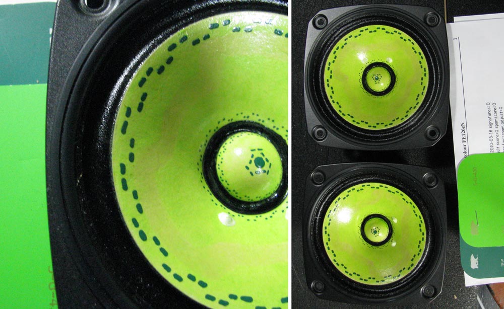
It's not easy being green -- just pictures

Note: this thread is the picture posts extracted from this active thread http://www.diyaudio.com/forums/planet-10-hifi/166518-its-not-easy-being-green-apologies-kermit.html


One of the nice things about the white Fostex cones is that they can be made almost any colour... here is a recent set i did for a client in NY.

Green-on-green-FE126e.jpg


She likes these better than her TB 1772 (both sonically & cosmetically). I expect the TB to land here soon for the same treatment.

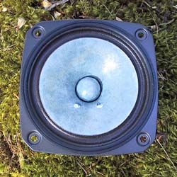
Here is a robin's egg blue FE126. These are in the UK now... they are pre-EnABL.

blue-fe126-onMoss-tn.jpg


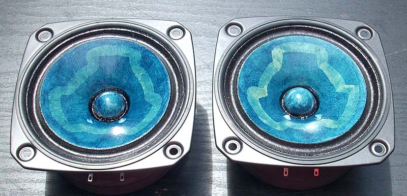
Another shade of blue... pretreated (and matched) for the client to do their own EnABL

nigel-hall-blue-preTreat-FE.jpg


More to follow.

dave

Converting duffle bag to boombox

Hi there!

Over the past few weeks I've been wanting to transform a duffle bag into a boombox which I can bring along to parties and chill sessions with friends. It needs to be battery powered, which I plan on accomplishing by building a 18650 battery pack. The charging circuit shouldn't be that big of a problem since I do have some electrical engineering experience. I also have a spare power supply from a PC lying around (Corsair CX650M, 650W), which I can use to power the amplifiers.

We mostly listen to bass heavy music like house, hip-hop, techno. So the speaker should be tuned more towards the bass side.

Since size is limited to about 31cm in height, 49cm in length, and 29cm in width, I'm not too sure how to get the most amount of bass while also leaving room for the other speakers & electronics. I'm currently looking at the Dayton UM8-22 (8") as a subwoofer driver (which could potentially be swapped with a low-profile driver if space becomes too limited) paired with an ICEpower 300AS1 amplifier, which will handle up to 300W Rms.

I don't think a ported enclosure will fit so it'll have to be a sealed enclosure or with a passive radiator (which I don't know much about). The specifications of the driver mention a 0.35 cubic ft (about 10 liters) net internal space for a sealed enclosure, which should give a Qtc alignment of 0.8 (I don't know whether that will sound great for my application).

For mids I have picked the Dayton Audio PA130-8 (5"), because the reviews looked promising. I don't really know what I should look for in a mid-range speaker otherwise. The sensitivity also seems to line up pretty nicely with the subwoofer. I've picked a Dayton Audio DC28F-8 (1-1/8") as a tweeter.

I've not run any numbers through a simulation yet, since I don't know how to do so. I'm currently looking for advice for picking the correct drivers and help with designing the enclosure.

I think this would be a fun project. Looking forward to reading your suggestions!

Jerre

6N2 6P14 OPT Phase reveral

Hello - my son has just completed his first valve amp kit which is a ChiFi using 6N2 and 6P14 with dual 6Z4 rectifier valves. After the usual checks, powered on and it's working! We found that one of the channnels has the phase reversed. Ok, we could just connect the speaker in reverse but I'd rather 'fix' the amp.

The OPTs are wired correctly so it could be that "B" (red) and "P" (green) wires on one OPT are internally swapped on the OPT itself? If we swapped the B and G connections for one channel, what would happen to the NFB for that channel?

There's some mains hum as well, so I'm assuming we may have to play around with grounding and/or shielding.

Any upgrade tips? He's interested in trying different valves already 🙂

Attachments

high frequency buzzing noise from muted line out

Hello, I recently acquired a DAC/Headphone amp combo with Line level out (Schitt Fulla E) to use with my PC monitors and headphones. The headphone input is supposed to mute the line level output when headphones are connected, and it does, but when I do so, the speakers play a very loud high frequency buzzing sound (I can identify the frequency but its definitely not 50/60 hz and shouldn't have anything to do with mains noise). No such buzzing occurs when the headphones are not connected (except from the much quieter, different in tone, hum noise every amp has ) The DAC is powered with usb directly Form he computer, in-between them i have a isolation transformer(groundloop isolator) since I had problems with ground loop noise because the pc and speaker amp share a common ground. Any Idea on how i should approach this? The buzz is very loud and I keep having to turn on and off my amp.

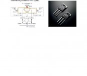
Yamaha's new floating and balanced power amplifier

Latest High End HiFi power amplifiers from Yamaha use their floating and balanced circuit. Power transistors are same polarity MOSFETs for both halves of waveform and the circuit is complety floating. Any ideas for DIY version? Do you think that it is promising circuit?

Yamaha says:

The basic design of the power amp circuit adopts Yamaha’s own, uniquely developed Floating and Balanced Power Amplifier technology. Adopting output elements with the same polarity on the plus and minus sides of the output stage, and also completely separating the NFB (Negative Feedback) circuit and power supply into total of four plus and minus sides of the left and right channels, results in thoroughly symmetric push-pull operation of the output stage, Completely floating the entire power amp circuit from the ground removes any negative impact of minute voltage fluctuations or ground noise. Moreover, the output elements are comprised of MOSFETs, which provide a warm and natural sonic character. The use of MOSFETs, which have the same polarity on the plus and minus sides, further evolves the ideal of a complete symmetrical design, to eliminate sound quality variations due to difference in polarity—a major distinguishing characteristic of the Floating and Balanced Power Amplifier—resulting in sound with a superior signal-to-noise ratio and superbly well-defined sound field.

Attachments

  • Yamaha floating and balanced.JPG
    Yamaha floating and balanced.JPG
    26.3 KB · Views: 2,377

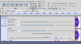
Using Audacity to equalize mp3 on CD

Here is the problem. I have been able to download mp3s under a subscription, and I have several albums downloaded at this time. I also prefer to use a DVD player as a source, with mp3s written to CD as data. My speakers are Wharfedale Diamond 4s.

Original audio CDs sound fairly good, but at the low levels I listen at, 72dB at listening position and 80 dB at 1 metre, I do not get the clarity and punchiness that I am used to, and I know from using headphones on the same tracks, or using a phone output with equalizer, there are some sounds that are lost. Obviously this is not what the recording was intended to sound like.

I do not have an equalizer so I had the idea of processing the mp3s using the Audacity application and exporting the files to disk, then copying them to CD. The results are fine, and I feel I am restoring the sound of the recording rather than simply equalizing to my tastes.

Two question to begin:

1. Has anyone tried this and has it worked out?

2. Have I missed anything here?

I will attach pictures of my DVD player, home made amplifier (TEA 2025 ) and speakers.

Initially I tried Bass and Treble boost, it did not work out too well.

Attachments

  • image_2022-03-17_170248.png
    image_2022-03-17_170248.png
    25.2 KB · Views: 171

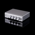
Pass DIY tone control?

Wishful thinking. Since it very, very soon is time for Christmas :xmasman: Well, not really... 🙂
A high quality DIY three band tone control would be a fun and useful piece of kit, in my humble opinion!

Say:
Band 1 centered around 60Hz - where the strong and juicy bass lives.
Band 2 centered around 2500Hz - where the harchness lives.
Band 3 centered around 12000Hz - Where the airy treble starts.

+/- 6dB adjustment

My wishful thinking and thougts inspired by: https://www.schiit-europe.com/product/loki-mini-high-quality-tone-control-2/

What do you guys think about a old school thing like the tone control? Could Be Fun, or Is it just one of the deadly HiFi sins? 🙂

Attachments

  • schiit-loki-mini-correct-600x600.jpg
    schiit-loki-mini-correct-600x600.jpg
    22.1 KB · Views: 190
  • Like
Reactions: Halauhula and Plott

List of tubes with same pinout as 6V6, 5881, 6W6, etc?

Hellois.
Anyone have a list of beam tetrodes and pentodes with same pin-out as 6V6 etc? I want to try all different types but only the types fitting into the same socket. EL34 and the like as well (where screen must be connected to cathode externally).
Does that tube base with that pin out have a nomenclature? I can search myself if I know that name.
(I know they have different electrical characteristics, and that is the point.)
Thanks

3 Bogen tube mixer/amplifiers MX60 & MX60A

3 Bogen tube amplifier / mixers, 1 MX60 & 2 MX60A, I found these at a swap meet today, and am selling as is untested. These are in good shape no dents or rust and have great tubes. The 2 MX60A amps run 3 GZ34 rectifiers 4 are Mullard 1 is Amperex Bugle Boy and the other is GE Power tubes consist of a set of brown base 7581, a set of 8417s and a set of 7027, there are a slew of Mullard 12ax7, plus an RVCA black plate 1 Telefunken a few Realistic 7025 4, possibly 12 microphone transformers as well as the 3 output and power tranys. These are a wealth of parts or 2 nice 60 watt monoblocks with a spare. I am looking to get $225.00 for the 2 MX60A amplifiers as a set and $100.00 for the MX60 or will sell all 3 for $250.00. Please send me your email address for photos.

WTB: LME49830

Hello, I am attempting to build a set of monoblock amplifiers designed by a former colleague who passed away in his memory and it requires LME49830TB drivers. I am looking for 4 pieces if anyone has any, please shoot me a PM! Yes, I see them on eBay but most appear fake and due to the quality and complexity of this amplifier I cannot take that chance.

Surplus Amplifier Development Power Supply PCB's available

Good morning all.

This might be of interest to some here. Anyone interested shoot me a line, looking for $5/board + postage.

I have four leftover PCB's from a audio bench power supply I built a few years ago, specifically designed to develop and test stereo audio amplifiers up to about 50W/channel. (Minimum board order at PCBWay is 5)

Output depends on the transformer used. Output caps would need to be sized for the transformer voltage and so on. For my supply I used an salvaged transformer from a Pioneer SX-750 receiver. I get main power of +/- 40VDC or 56VAC (60Hz), +/- 52VDC auxiliary power and 8VAC (the fairly universal lamp power for filament bulbs in 70's stereo components).

IMG_20220410_093257955.jpgIMG_20220410_093836490.jpgschematic.png

New Quadral (Technics) TH 400 ribbon super tweeters

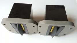
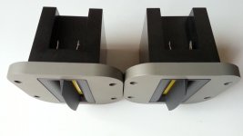
New Quadral (Technics TH400) ribbon super tweeters

For sale is a pair of high-end capton ribbon super tweeters Sold

Attachments

  • 20140712_184919.jpg
    20140712_184919.jpg
    546.3 KB · Views: 847
  • 20140712_184957.jpg
    20140712_184957.jpg
    529.2 KB · Views: 593
  • 20140712_185039.jpg
    20140712_185039.jpg
    508.3 KB · Views: 520
  • 20140712_185217.jpg
    20140712_185217.jpg
    866.5 KB · Views: 480
  • 20140712_185428.jpg
    20140712_185428.jpg
    578.6 KB · Views: 426
  • 20140712_190559.jpg
    20140712_190559.jpg
    464.5 KB · Views: 313
  • 20140712_190756.jpg
    20140712_190756.jpg
    449.7 KB · Views: 372

Hornresp Paraflex models - Type 1 - Folding layout?

Hi there,

I cannot find any information on what the Hornresp Paraflex model schematics ('Type 1, 2, 3, 4') actually represent.

I know the way you fold the cabinet is not the same thing as the schematic.. But I can't tell what is implied by the circles around the tap or throat points and the extra segments (6,7,8,9), though I have found their cross sectional area is represented in the Schematic 1 window.

Any ideas?

ES9038pro register mystery

While writing a program to play with the THD compensation registers on my ES9038pro, I read the datasheet for other settings that would be nice to be able to change, so I could do it in an all-in one program.

That is when I noticed that in the latest online datasheet from ESS ES9038pro, now v3.7, the description of the registers Register 61-57 had changed from “Reserved” to “DAC Scaling”. Not (yet?) in the ES9028pro datasheet, though.

The registers are described as A 12-bit unsigned value that scales the input to the 2/3/4nd DAC from the 1st DAC in each of the 8 DAC channels. Each channel contains 4 DAC’s summed together.

Googling and searching forums, I couldn’t find any useful information on the workings of these registers. In their paper on the Hyperstream architecture, it is mentioned that each DAC is actually a balanced pair of the DACs. Maybe it has some relation to this?

Strangely, the default values are 0, which would indicate no signal is sent to DACs 2-4? To make things more confusing, the datasheet states that ‘A value of 12’4095 (0xFFF) will set the input at full scale, maximizing the signal to noise ratio’. But the default is 0?? Why??🤔

I cannot imagine, however, that the default value is non-optimal, but maybe there are other trade-offs, such as THD?
I don’t want to tinker with this setting without knowing what is does. Does anybody know more about this mysterious matter?

Help me with a hum problem?

I am stumped 🙁

I've recently resurrected a DIY multi-channel amplifier that I built about 15 years ago, mostly from commercial kit PCBs. It has balanced inputs and was previously used with a DCX2496 (balanced outputs) with no hum, until the DCX2496 died and I later blew up a channel on this amp. Fast forward, the DCX2496 is replaced with a Dayton DSP-408 and the amp is repaired... but it hums with a very slight buzz if there is anything connected to an input.

If no amp inputs are connected, it is quiet - it's not going to win any nV^2/Hz awards, but good enough to have in the loungeroom. As soon as I plug a cable into the inputs, it starts humming. If I touch the end of the cable, obviously lots of noise. Plug the cable into the output of a source (e.g. DSP-408, or the pre-outs of a receiver) and the hum is there - for the channels that are connected.

With some signal playing through it, it sounds fairly good but that hum is audible and very annoying during quiet parts. I suspect it also exists in the mid+tweet channels, which cannot be a good thing even though it's only a couple hundred mV.

The amplifier and its sources are all in the one rack; there are no long cables except the speaker cables. The rack has a PDU and it's all powered from a single powerpoint.

The amp box is a steel 3U rack case, very full, which contains:
  • 2x300VA+20VA toroids feeding classic bridge rectifier + cap power supplies at +- 36V, 50V and 60V.
  • the low voltage supply powers four 50W chip amps (for mids+tweets)
  • the high voltage supplies drive a pair of 100W discrete AB amps (for woofers)
  • an arduino doing fan-control work plus switching the mains in accordance with a remote-in signal, etc
  • outputs go to a pair of three-way speaker boxes via 8-pole speakons and braided fig-8

The fact that it's quiet with no inputs connected means that I don't think there are any severe ground-topology issues in the power supplies, e.g. there are no rectifier currents within the signal path that cause the classic buzz.

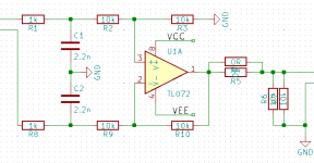
Inputs are/were differential, using a very simple active differential receiver - see attached schematic (which doesn't include decoupling but obviously it's there). I will not pretend that it has fantastic CMRR but it has previously not been a problem, and the cables in use are very short. It's assembled using a PCB of my own, NE5532s and 1% thin-film resistors, all 0805. The balanced-received circuits have a linear regulated supply which is derived from the 36V supply for the chip amps, therefore the ground of the unbalanced outputs is the ground of the chip-amp (+-36V) supply. Because there are 6 differential receivers with unbalanced outputs which all share a single ground, this is the point where the grounds of the two different amplifier-types join up. There is skinny shielded wire from the balanced-receiver SE outputs to the input of each (SE) power amplifier, and these shield/grounds all meet at the differential boards.

The input ports to the box are XLR wired in the usual way. Pins 2 and 3 go to the balanced input circuit, pin 1 I have tried to chassis-ground, power-supply ground, or floating. I have short - too short! - RCA to XLR cables which are used as the inputs. They are mic cable, two-core with a screen. Screen goes to pin 1 at the XLR end, red and white go to pins 2 and 3. At the RCA end, the tip and sleeve go to red and white, i.e. the screen is (was...) discontinuous at the source end.

Chassis ground of both the amplifier and the source (pre-outs on a Yamaha receiver) are connected together through the PDU: Class I safety grounds. The Yamaha has RCA outputs, the screen of which is connected to chassis ground within the Yamaha. The pre-outs go via the DSP-408; the DSP is powered from a floating (Class II) DC wall-wart and it connects the screen/ground of all of its input and output RCA ports together internally as you'd expect.

Things I have tried so far, to no avail:
  • connecting PSU ground to chassis ground (good), or floating (a bit unsafe)
  • with PSU ground floating, connect ground at the differential input board to chassis ground (slightly less unsafe but still not great)
  • connecting and disconnecting screen (pin 1) in XLR sockets to chassis ground
  • remove the differential input boards, connecting the inputs of each amp board directly to pins 2+3 of the XLR sockets (this connects the grounds of the two power supplies only via the sleeves in the various RCA jacks - quite unsafe, and a risk to the DSP if there were a PSU fault)
  • connect and/or disconnect the screen of the cables to the RCA sleeve at the source end, thereby tying the source & amp chassis together through cable-screens, or not

That's a bit of a wall of text sorry, so I am drawing out all the internal and external wiring now in KiCad.

If anyone can spot my error and say "this is what you've done wrong", great, otherwise I'm looking for suggestions for things I can test in order to try to isolate the problem.

I saw this thread but I am not sure it applies here. The differential inputs should provide sufficient separation between the grounds, or so I thought... There are definitely ground loops inside the case, e.g. via the screens of the unbalanced signals from the balanced inputs, to the amp boards, then back through the PSU via 2 paths, but they do not seem to be causing any problem, noting that it is silent with the inputs floating.

Attachments

  • bal-input.png
    bal-input.png
    3.9 KB · Views: 185

Topping D50 DAC does not power on

My Topping DAC D50 does not power on. I tried different USB charger 5V-1.0A and 2.0A.

Did anyone experience the same problem?

I hear it "click" on, but indicator light (display) does not light up. Has anyone any ideas how to get it working?

Thanks.

Attachments

  • IMG_6224.JPG
    IMG_6224.JPG
    100.5 KB · Views: 699
  • IMG_6225.JPG
    IMG_6225.JPG
    77.2 KB · Views: 632
  • IMG_6226.JPG
    IMG_6226.JPG
    108.9 KB · Views: 864
  • IMG_6228.JPG
    IMG_6228.JPG
    170.1 KB · Views: 1,151
  • IMG_6231.JPG
    IMG_6231.JPG
    126.9 KB · Views: 1,226

F8 inspired transconductance amp with Aleph CCS

I have another one of my sucessful experiments!

I have a thing for transconductance amplifeirs (high output impedance). My last successful amp was a modified Aleph J but while it works I wanted to play around some more. A problem also is that the first step in that amp is to reduce the voltage feedback this makes it take a lot longer to bias up. The schematic in that thread takes ~ 10 seconds to bias with 2 turn on thumps. I also want to have automatic turn-on-off when playing audio so fast biasing would be nice. I also have a set of Semisouth R100s which would be fun to use in a single ended amp =)

I've been thinking about a J2 clone but it would have the same problems with biasing as the Aleph J but mostly it requires 2 matched quads of LSJ74s and I only have 2 matched pairs. But I started looking at the F8 simplified schematic and thought: hey, wouldn't it be really simple to convert this into a transconductance amp and I already have enough LSJ74s to build them:

Current source F8 simplified schematic.png

I used zchoppers posted F8 circuit as a basis and then got to work:

Ollbolls Aleph F8 mutated into a current source amp.png

From previous experiments I have found that the mu follower CCS with current feedback makes the output have mainly 3rd harmonic where an Aleph CCS still produces 2nd so I threw in the CCS from the Aleph J.

It works great in the simulation so I decided to go ahead and build it in practice and it works!

IMG_0044.jpg

In the simulation it had 50 ohm output impedance @ 10 hz and ~ 800 at 100 hz and upwards. And the real circuit measured at 780 ohms @ 2 khz 😍

And at 25W into 7.7 ohms it had 0.55% 2nd distortion and 0.43% 3rd and falling higher order distortion. And below that the 3rd and higher harmonics dropped like a stone and only the 2nd was left which is exactly what I wanted.

It probably has slightly higher distortion than Nelsons variant since I have 20 dB gain instead of 15 dB but should be low enough. The distortion only rises significantly when pushed to the limit and I won't listen that loud anyway.

Ollbolls Aleph F8 mutated into a current source amp distortion @25W.jpg

It biases very quickly too, done in 1s which is nice but all is not well yet. It has a nasty turn on thump and a smaller turn off thump. The plan is to add a delay to connect the speakers and then disconnect it immediately on turn off. I have circuits that in simulations seem to do the job.

The next step is to design some PCBs so the amp doesn't look too much like a test bench.

Standard Schematics, Class B and Class AB

I, usually, do not like to write and publish documents on standard schematics. I like to make own schematics.

However, I think, the standard schematics are very important and very popular. So, I have decided to compile a document on these. I could not resist to add something original to some of the schematics, which is marked as such and can be skipped. The main topic, however, is the standard schematics.

I have not addressed stability and oscillation problems, which, were described in a separate document, along with ways to reduce and eliminate them. I have, however, briefly mentioned these in the document, very briefly.

The document is, mainly, dedicated to the principle of work of the standard schematics. After each figure, there is a fast analysis of the principle of work, called " Key to the Schematics ".

Initially, I wanted to make a fast and brief, extremely concise document, which, I was unable to do, as usually, yet, tried as much as I can. The document became long and I can, only, hope I have not made many mistakes.

The document is called " Standard Schematics.doc " and is here :

https://drive.google.com/drive/folders/1I-gJFsjT1I2w7QNfagujAo1DXqRQrGxG

Best free RPi OS for Hifiberry DAC + ADC besides Volumio, moOde, HifiberryOS....

I need an OS that will easily allow me to use my analog input for free.

Volumio's subscription fee is just a bridge too far for me.
moOde gives me access, but requires too many menu dives (wife won't go for it)
Ironically, HifiberryOS is ridiculously unstable and buggy, at least through the touch screen. The input select rarely works and the screen freezes up after maybe 10-15 minutes of operation.

What other free options are out there with Spotify Connect/BT/a simple and reliable way to access the analog input?

Is it possible to modify the moOde interface/home screen?

replacing snapped off capacitor lead

A lead on a Obbligato cap broke off. The cap has a lot more life and I'd like to replace the lead. The stub of the lead is about .5mm proud of the end cap so I'm thinking of putting a drop of solder on the stub and then tining the end of a new lead. Then I will heat the end of the lead and push it into the drop of solder on the stub. Has anyone done this type of repair? All thoughts/ideas will be appreciated.

Horn loaded tubby/house bass help..

I used to own a double stack of original martin 115B bass bins and matching tops.
They ripped… Now Im trying to DIY some new bins and overwhelmed with plans and specs from various build sites..

I want that sound again, BUT:

—smaller cab size
—reasonable cost driver
—better response/sens
--
—more efficient
—BUT… I am looking for that same tubby resonant growl, ripping disco bass, and house grind bass, is the best way to explain it.
— So a little color is ok, this is not a purist hi-fi situation. Its about bringing some Fundamental and harmonic “musically” tuned bass bins to the people, on the roller rink, dance floor or open grassy plains....

I have reviewed “all of the stock” plans on this and most sites.. and am at loss on what to make a commitment with, and start duplicating for the people.

Also open to tops matching recommendations.

Im ready to rip space/time again and bring joy to all of us post-covid folks …Please help guide me 🙂

Universal buffer with balanced/unbalanced switch

Hello everyone!

I am trying to come up with schematics for the universal input buffer that would use balanced and unbalanced connections for the input. I have placed a switch at the end after the op-amplifiers, but not sure if that will work well?

I also added power regulators LM317, LM337 that will allow to power this from the DC supply of 15V to 40V with center ground.

Idea behind this board was - to be able to combine it with any power amplifier boards out there. For example, LM3886, TDA7396, or discrete amp like JAT501. Since it is a buffer, you can use chip amp in inverted schematics.

Something similar is done by Tom from Neurochrome - https://neurochrome.com/collections/buffers-preamps

However, those boards don't come with input connectors, so I wanted to add those.

Any thoughts or input will be greatly appreciated,

Pavlo

3d-start.PNG
switch.PNG

Attachments

  • sch.PNG
    sch.PNG
    34.6 KB · Views: 509
Projects by fanatics, for fanatics
Get answers and advice for everyone wanting to learn the art of audio.
Join the Community
507,691
Members
7,884,402
Messages

Filter

Forum Statistics

Threads
406,050
Messages
7,884,402
Members
507,691
Latest member
Deedy