I have another one of my sucessful experiments!
I have a thing for transconductance amplifeirs (high output impedance). My last successful amp was a modified Aleph J but while it works I wanted to play around some more. A problem also is that the first step in that amp is to reduce the voltage feedback this makes it take a lot longer to bias up. The schematic in that thread takes ~ 10 seconds to bias with 2 turn on thumps. I also want to have automatic turn-on-off when playing audio so fast biasing would be nice. I also have a set of Semisouth R100s which would be fun to use in a single ended amp =)
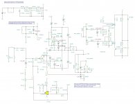
I've been thinking about a J2 clone but it would have the same problems with biasing as the Aleph J but mostly it requires 2 matched quads of LSJ74s and I only have 2 matched pairs. But I started looking at the F8 simplified schematic and thought: hey, wouldn't it be really simple to convert this into a transconductance amp and I already have enough LSJ74s to build them:

I used zchoppers posted F8 circuit as a basis and then got to work:

From previous experiments I have found that the mu follower CCS with current feedback makes the output have mainly 3rd harmonic where an Aleph CCS still produces 2nd so I threw in the CCS from the Aleph J.
It works great in the simulation so I decided to go ahead and build it in practice and it works!

In the simulation it had 50 ohm output impedance @ 10 hz and ~ 800 at 100 hz and upwards. And the real circuit measured at 780 ohms @ 2 khz 😍
And at 25W into 7.7 ohms it had 0.55% 2nd distortion and 0.43% 3rd and falling higher order distortion. And below that the 3rd and higher harmonics dropped like a stone and only the 2nd was left which is exactly what I wanted.
It probably has slightly higher distortion than Nelsons variant since I have 20 dB gain instead of 15 dB but should be low enough. The distortion only rises significantly when pushed to the limit and I won't listen that loud anyway.

It biases very quickly too, done in 1s which is nice but all is not well yet. It has a nasty turn on thump and a smaller turn off thump. The plan is to add a delay to connect the speakers and then disconnect it immediately on turn off. I have circuits that in simulations seem to do the job.
The next step is to design some PCBs so the amp doesn't look too much like a test bench.
I have a thing for transconductance amplifeirs (high output impedance). My last successful amp was a modified Aleph J but while it works I wanted to play around some more. A problem also is that the first step in that amp is to reduce the voltage feedback this makes it take a lot longer to bias up. The schematic in that thread takes ~ 10 seconds to bias with 2 turn on thumps. I also want to have automatic turn-on-off when playing audio so fast biasing would be nice. I also have a set of Semisouth R100s which would be fun to use in a single ended amp =)
I've been thinking about a J2 clone but it would have the same problems with biasing as the Aleph J but mostly it requires 2 matched quads of LSJ74s and I only have 2 matched pairs. But I started looking at the F8 simplified schematic and thought: hey, wouldn't it be really simple to convert this into a transconductance amp and I already have enough LSJ74s to build them:
I used zchoppers posted F8 circuit as a basis and then got to work:
From previous experiments I have found that the mu follower CCS with current feedback makes the output have mainly 3rd harmonic where an Aleph CCS still produces 2nd so I threw in the CCS from the Aleph J.
It works great in the simulation so I decided to go ahead and build it in practice and it works!
In the simulation it had 50 ohm output impedance @ 10 hz and ~ 800 at 100 hz and upwards. And the real circuit measured at 780 ohms @ 2 khz 😍
And at 25W into 7.7 ohms it had 0.55% 2nd distortion and 0.43% 3rd and falling higher order distortion. And below that the 3rd and higher harmonics dropped like a stone and only the 2nd was left which is exactly what I wanted.
It probably has slightly higher distortion than Nelsons variant since I have 20 dB gain instead of 15 dB but should be low enough. The distortion only rises significantly when pushed to the limit and I won't listen that loud anyway.
It biases very quickly too, done in 1s which is nice but all is not well yet. It has a nasty turn on thump and a smaller turn off thump. The plan is to add a delay to connect the speakers and then disconnect it immediately on turn off. I have circuits that in simulations seem to do the job.
The next step is to design some PCBs so the amp doesn't look too much like a test bench.
Last edited:

Very nice and the THD figures @25W look great! 
Any chance you have THD/H2/H3 figures for 1W into the same load? Have you given it a listen yet?
Cheers,
Stephen
Any chance you have THD/H2/H3 figures for 1W into the same load? Have you given it a listen yet?
Cheers,
Stephen
I didn't measre at 1W because the noise was so high I didn't think I'd get useful data at only 1W. I think I forgot to connect the input ground to the circuit ground. The input is floating through a transformer because the output negative is above ground. But I have measured before in a similar setup with far less noise such so when I fix the problem I should be able to gett good measurements at 1W. I can do such measurements next weekend when I get to play in the workshop some more 🙂Very nice and the THD figures @25W look great!
Any chance you have THD/H2/H3 figures for 1W into the same load? Have you given it a listen yet?
Cheers,
Stephen
And I did listen to it with a 6.5" test driver full range and it sounded pretty nice. Most similar to other single ended current source amps I've liked like the transconductance converted Alpeh J and an F2 inspired clone. There was a bit too much high end though because I hadn't adjusted the frequency for the rising frequency response with a current source though.
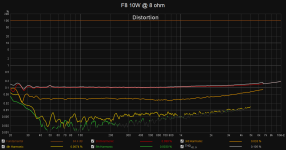
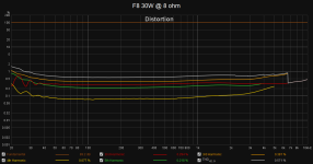
Here are some better distortion measurements:
I don't like the rising 3rd order distortion though. My hypothesis is that it is because my current bench source has a pretty high output impedance (10k). Tomorrow I'll redo the tests with a 20 ohm output impedance source and see if the distortion goes away.
But apart from that it measures pretty awesome 😀
Attachments


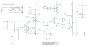
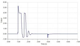
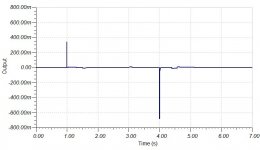
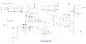
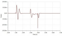
Here is my most recent circuit when toying around. The main F8 inspired amp is the same but now I have added some thump suppression: The thump images are voltage across the 7 ohm speaker during turn-on (1.00) and turn-off (4.00).
It would be nice to remove the on thump completely but I think I'd have to use a normally on type for the lower shorting FET. Since the speaker is at 0V potential I'd have to add a negative supply though which adds complexity so for now I've gone with a normal enhancement mode mosfet. I've tried to completely suppress the off thump too but I haven't succeeded. The bigger spike, however, is now just a single period 150 hz tone @ 700 mV which isn't that big of a deal so I might just ignore it.
Apart from that I keep thinking if I can simplify or improve it. I'm no expert and have no prior experience, just toying around with the simulating software to see what works and what doesn't 😀
Attachments
Last edited:
I think I've succeeded in completely suppressing the turn-on thump at least. I added a small 10uF cap to the upper series protection mosfet to make it turn off slightly slower.
I wonder if I'll be able to completely suppress the turn-off thump too.
I wonder if I'll be able to completely suppress the turn-off thump too.
Attachments

well, few weeks more, and you'll be close to my own level of unnecessary complexity of amps

question: thump confirmed/shown in vivo, or you're expecting it from sim results?
question: thump confirmed/shown in vivo, or you're expecting it from sim results?
Both, on the bench I got a turn-on-thump of 10-20V on my voltmeter if I remember correctly hence my obsession with eliminating it. To not risk destroying my test speakers on the bench I added another small series cap to the output caps to reduce the capacitance from 4.7 mF to 220 uF or so, then the thumps are much smaller. Also I want to add an automatic turn-off when not playing audio for say 1-5 min so it will be switching on and off a lot.well, few weeks more, and you'll be close to my own level of unnecessary complexity of amps
question: thump confirmed/shown in vivo, or you're expecting it from sim results?
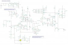
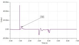
And on the next iteration I've supressed the thumps even more:
The turn-off thump got eliminated if I added a 100 uF capacitor to the input JFET bias. The turn-on thump came back so I eliminated that one by adding a turn-on delay with a P mosfet such that all the protection mosfets are biased before the amp turns on. Easier than fiddling with a negative bias and normally on devices =)
I've also played around with an opamp bias so I don't have to fiddle with a pot, measures pretty much the same as the pot bias.
But yeah, a lot of surrounding complexity around a very simple amp 😀
Attachments
- Home
- Amplifiers
- Pass Labs
- F8 inspired transconductance amp with Aleph CCS