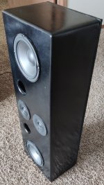
Need Help With EZ80 Rectifier

Need Help With EZ80 Rectifier for DAC

I am teaching myself some tube knowledge and thought I would start with a clone of the Border Patrol DAC. I know that DAC uses off the shelf XMOS and DAC boards with no output buffer so that portion is simple. The DAC board power supply must be between 11-20V DC.

As shown in the attached photo I found of the DAC internals, the power supply is an R-Core transformer fed into a circuit having an EZ80 rectifier and what I think must be a diode rectifier because the tube can be switched in and out of the circuit. The attached photos show the heater and filament supplies (red and grey wires) to the tube rectifier PCB. There are two center tap wires (white wires) from the transformer directly to the ground on the DAC board. The rectifier PCB has a pair of diodes and a pair of resistors at the bottom, a pair of tantalum caps and a third resistor having a stated value of 10k (the bands indicate the actual resistor value is 4.7k 5%) that is maybe for current limiting. The rectified power (black wire) then passes through a choke and then to the DAC board. There is a cap across the V+ and ground at the DAC board inputs.

So this is the total of my knowledge of the power supply. Can anyone help me figure out the rectifier schematic and the proper component values and voltages for the transformer supplies? I am think about just using the EZ80 rectifier without a switch for taking the tube in and out of the circuit.

Thanks in advance.

Attachments

  • IMG_1967.jpg
    IMG_1967.jpg
    850.2 KB · Views: 517

Adcom GFA 555 info -

Hello. I just joined yesterday. I saw a youtube video with Nelson Pass being interviewed and thought this sounded like a great resource.
I am currently taking apart one of my Adcom gfa 555 amplifiers. White fluid began leaking from the bottom and when I opened it, I saw that it was coming from the transistors. Or rather the thermal paste from the output transistors. In order to clean it properly and not damage anything, I have to take apart the rear a bit and I wanted to test things like capacitors and any other parts that are known to go bad. I was thinking that this would be the perfect place to ask about it, since I’d read that Mr. Pass designed these amplifiers.
If there is anyone out there who would not mind sharing some information, I would greatly appreciate it.
Please do not tell me not to do it. I
Am on here seeking information about this equipment.
I do not wish to pay a shop hundreds of dollars. They quoted me $200 a few months ago to change a fuse.
I decided to do it myself. Some weeks back, this particular amp had a burning odor coming from it. Not smoking, just like the smell of plastic heating up.

I’m also building some external crossovers for my Magnepan speakers. Still waiting on some parts I ordered a couple of months ago.

I recently purchased a digital multimeter, a soldering iron and yesterday purchased an lcr meter.

Thank you very much, in advance

ILP toroidal transformer type numbers

Sometimes I see people looking for type data of ILP toroidal transformers.


This is an old sheet. I post it here before the mice eat the rest of the paper.


In Dutch Type nummers ILP ringkern trafos.

Attachments

  • Like
Reactions: Optician

Any use for Sanken SAP15 (6x N3KO 3920/ P3KY 3918, 1x N80 3704/ P80 3705)

Hi people,

I pulled these Transistors out of a Kenwood KRF-9080D AVR. As I'm just a mechanic (and still a newbie in diy-audio), I'd like to ask you what I could do with them? I've read the Datasheet, and know those are a little "special".
Is it possible, to use some for a Subwoofer-Amp (I'm building one atm with IRFP240/ IRFP9140, but havn't tested it yet)? Or could I use these Transistors in a Cap-Multiplier? Or, if there is a market, should I sell or swap them?
What would you do?

best regards
J.

Attachments

  • Kenwood TRAIT N3KO-P3KY_ SANKEN SAP15 500w.jpg
    Kenwood TRAIT N3KO-P3KY_ SANKEN SAP15 500w.jpg
    47.3 KB · Views: 480
  • SAP.PNG
    SAP.PNG
    18.7 KB · Views: 402

Need help with NAD amp! Goes in protection

Hi! I may be of topic but i didnt now where to put this,

I recently got my hands on a NAD C350 integrated amp.
(home stereo).

But the amp goes in protection after 2-3 seconds.

I have checked the output transistors and they seeme to
be OK.

And i checked the drivers, and the seeme to be ok.
A litle hard to measure because the have mirrored
the pins on that transistor modell.

I removed all the drivers and started the amp.
And i got green light! 😉

But what the hell? I measured them and there is no
short from what i can se. they all measure about 0.6 in
diod check, and same for the outputs.

Anyone have a clue what could be the problem?

I saw inside the case that signal earth had been repaired
for a couple of years ago. And i saw a fixed print. But cant
find anything that looks broken.

But you can se that the board is a bit darker around
the drivers and then there is 3 other transistors.
But none of them seemes to have a short.

Oxygen Audio AirPro M2.5K

Hello
I have a problem with my Oxygen Audio AirPro M2.5K amplifier.

When I turn it on, the green indicator lights up then the protection indicator lights up and its without the power MOSFETS.

I did some tests = a 7812 HS regulator and at the driver board level I had HS transistors such as Q5 Q9 Q12 Q6
Do you have any ideas of what to try out?

Q5 is DK mark QF is it 2SC4672?

What about Q9 2SA1797?
Where can i find them or any substitutions?

Thanks a lot and sorry for the language it's google translate.

Adcom GFA-5002 increase ClassA bias on purpose

First off ***WARNING*** this is an experiment/for personal enjoyment and could be wrong and dumb, please don't do it.

I took this perfectly workable amp, and purposely upped the bias slowly by 1watt increments alternating left/right channel until I got to 90watts* (45watts a channel classA vs 6), up from 12watts out the wall factory.
Stopped increasing when the heatsinks hit 55degC idle and stable, heat was my limiter--> increase from fairly cold idle.

Why? Because this amp is an old backup, sounds kinda meh and I've been exposed to new amps and how they sound vs my classD.

Anyway this changed the sound, now has sweet dense tone, opened it way up, complex resolved transients and is fun to listen to. It does not sound like added distortion** or anything like that.
Is it just super warmed up, or more ClassA operation?! dunno YMMV


Could have dreamt it but, always thought about doing this because somewhere I swear Nelson Pass said why not crank the bias until the heatsinks are hot on his smaller Adcoms for more classA operation.

DC offset is still 14mV, 20mV -- that didn't really change. They both shift around +/- 3mV

Also I don't know the test point to properly bias it to factory, maybe someone has a snippet on how to do that on the 5002?

*by watching the power draw from the wall
**read you can check this by running a sine wave in and check the output sine for clipping, I am lazy and did not do this.

System: YggdrasilA2(UNISON/digionesig)-->Jenson 1:1 bal/se-->freya passive-->GFA5002-->Elac adante/debut 6.2 / MLdescent i x2

Thanks!!

Attachments

  • IMG_0017.jpg
    IMG_0017.jpg
    986.1 KB · Views: 770

JBL Studio 530’s as Synergy Donor

I recently got an pair of JBL Studio 530 monitors on sale for $250 direct from JBL. I was curious what an entry level horn loaded CD 2-way monitor could sound like. They actually sound quite decent and measure well when the tweeter is padded down a notch. The reviews of these are generally very good and for $250, no DIY project will come close really given the nice cabinet (no parallel walls in sight), a horn, passive XO, and decent bi-wire/bi-amp 5 way binding posts.

What intrigues me about these is that the horn has lots of opportunities for cutting slots and holes for mid range injection to make a bookshelf Synergy. Has anybody thought about doing something similar? My one reservation is that this speaker sounds very good as is and I would hate to cut into it.

Here it is next to my 10F/RS225 TL speaker for size comparison. It works well with either my Class AB or class D amps. It needs so e power though, probably at least 40w to really come alive.
attachment.php


This is how I padded the tweeter but adding a resistor between the woofer binding post and tweeter binding post.
attachment.php


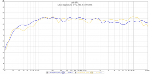
Here is how it measures with the tweeter padding in place. Without it, the response is a bit bright for my taste. The JBL 530 is the yellow trace and the blue is a new speaker I just developed with a typical “Harman house curve” voicing for comparison.
attachment.php


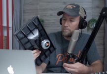
Here is what is interesting, Ron from New Record Day, did a tear down and you can see the inside of the horn. Lots of open surface area for mounting small 3in midrange cones for a mid injection a la Synergy.

Anyhow, I thought I would just throw this idea out there to see if anyone else has wondered the same thing.
attachment.php


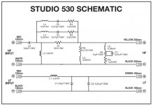
Here is the XO schematic from The manual:
attachment.php


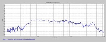
Here is the horizontal directivity from the ASR review:
index.php

Attachments

  • E7427651-3AAB-4F4F-9DBF-F9A47324595E.jpeg
    E7427651-3AAB-4F4F-9DBF-F9A47324595E.jpeg
    803.4 KB · Views: 3,276
  • F99799CE-13E6-4135-8359-7A444C978C48.jpeg
    F99799CE-13E6-4135-8359-7A444C978C48.jpeg
    671.5 KB · Views: 3,686
  • 71ED73C4-5316-49AC-ACED-E168B0CB72D4.png
    71ED73C4-5316-49AC-ACED-E168B0CB72D4.png
    174.1 KB · Views: 2,565
  • 03872FE6-6B9B-40BA-817C-51D8ED47F142.jpeg
    03872FE6-6B9B-40BA-817C-51D8ED47F142.jpeg
    684.8 KB · Views: 2,517
  • 5B7324F7-78DA-413C-BE55-0B42C785EE08.jpeg
    5B7324F7-78DA-413C-BE55-0B42C785EE08.jpeg
    247.6 KB · Views: 2,575
  • Like
Reactions: Naturlyd and Zvu

Matts RH84 build

Building an RH84 revision 2 with 5r4gy rectifier and Sony Tamradio power & Output transformers. The case is an old suite case \ portable record player - re vamped with many hours of sanding & spraying etc.

Problems so far, i noticed I have wired my 200uf cap as the first cap rather than the 47uf one. I will change this next its an easy fix.

The two 100uf 100v Kemet peg124 Caps that i bought are way off in value, one measures 98uf the other 128uf. Iam not going to use them. Probably order some rubycons.

I sure am running out of space too.

Attachments

  • 20220410_101740.jpg
    20220410_101740.jpg
    403.6 KB · Views: 330
  • Screenshot_20220415-002435_Gallery.jpg
    Screenshot_20220415-002435_Gallery.jpg
    234.3 KB · Views: 332

How to design a choke input filter?

Hi,

admittedly I don't have any clue of what's going on exactly in a choke input filter, besides the DC voltage is about 0.9 times the AC input and regulation is comparatively good (= stiff DC voltage) at more than some minimum load. But 'till now I've never designed a choke input PSU by myself. So there are some questions where I'd need some helpful answers:

  • Are there any formulae that allow for designing the choke and the first filter capacitor? What are the required parameters?
  • If there is a CT'ed secondary wining and I use a pair of SS diodes instead of a two way rectifier tube, there' some short time (depending on the secondary voltage and the diode forward voltage) next to the zero crossing when no diode conducts. As an inductor tries to keep the current flowing, would a third diode wired reversely between the rectifier output and the CT help the choke to do it's job? I've never seen this, anyway, but I wonder why this helper diode usually is omitted? Would regulation be compromised by such a diode?

Best regards and TIA!

Mission "M-Cube" help

Hi all
I have 1 Mission "M-Cube" subwoofer and I need some help...
The problem is that the primary switching mosfets (IRF740) gone up in smoke and I whant to fix it.
My problem is that there is some damage (melted film) on the transformer and I don't know if it is damage to the windings.
So before I smoke 2 new mosfets can someone give me some pointers ?
Personally I don't like switch mode power supplies in audio gear and I would prefer to build a normal one with a toroid but I dont know the voltage and VA output rating of the original supply.
Can someone help ?
The Mission site is nice but the contact page is not working.

Ric

High Power Class D

Welcome to the Diy Audio team. I'm also a new member and also learn a lot from this forum. It's great forum everyone share to help each other fulfill their passion. My problem is looking for Class D 1500w 8ohm to play super speakers large capacity bass. Can anyone who has a stable and well-functioning PCB share it with me as well as anyone else to experiment with. I would be very grateful if someone is kind

Real world feedback on THAM12 vs MTH30

Im getting closer to picking a sub design to build, thanks to a lot of feedback from folks here (thanks guys on helping me see the tapped horns are the new FLH).
Iv narrowed it down to the THAM12 or MTH30. Im finding that the cab size and frequency range balance is what I need for now.

Has anyone built both of these and compared in real life? If so wondering what your qualitative feedback is on sound, real world response (slippery slope I know), But also practical feedback, like:

-Best driver selection vs driver cost for each
-ease of build
-durability,
-Sound with stack of 6 cabs
-thought on matching tops
-or any thoughts..

Application is small club for now, but My plan is to build (2) 12" bass bins now , and add more later, and/or possibly add (2) TH18's later, but unsure if this is advisable..

To confuse things. The SS15 is on the radar too, but lets leave that unaddressed for now.

Playback system optimization

Hello,

I have a setup intended ONLY for spotify playback. I can never stop optimizing (see below), though it is running great 😉

System description:
Spotify (Streaming quality set to "very high", no "normalize" or any other function is enabled that could mess with the sound) on an older Linux Mint Laptop (I have defined "src-sinc-best-quality" in /etc/pulse/daemon.conf, though I do not know if it is resampling at all), connected over USB2.0 cable to -> Lexicon Alpha Studio, connected by 2 balanced analogue cables to -> DriveRack 260 (doing XOVER, delay match, EQ), connected by 3 balanced analogue cables
to Gisen audio D 4.15 4 channel class D (2 signals left and right > 100Hz, 1 signal mono bass <100Hz. I modded the amp and wired the chan 3 amp-input internally to channel 3 AND 4 power modules to support both my subs equally without the need of working with 2 attenuators).

Performance:
I can only do clean sweep tests using clementine, since my spotify does not support .wav.-files This is contrary to the system being intended to playback Spotify only, I know that.
I have created a perfect .wav-file that does 1Hz - 22049Hz at 0dB ascent sweep in linear way, sampled at 44100Hz, 16 Bit (I can share that one, in case someone is interested). The reason for 44100 was, that I think, Spotify will play in 44100Hz, when set to "very high quality", right?
I can hear the sound going up, until I can't any more (my ears are not very good). Just as the playback reaches ~21kHz, the system (actually the tweeters) starts to do some "whizzing" siren-like sound, that clearly should not be there at all. Since I cannot hear >15kHz at all, and I can clearly hear that artefact / aliasing noise, it is below 15kHz! Other that that, the whole system is working perfect. BTW, I know, 21kHz playback at full 0dB scale is not a typical use case, since most Spotify music does not contain > 20kHz at all, let alone at that level.

Questions: Is it true that Spotify is streaming 44100? What "target rate" for Lexicon Alpha Studio should I aim at? I guess, the DriveRack is doing 48kHz, right? Could not find that info within the whole internet... If so, aiming for the audio interface to do 48000 would maybe risk a "beating" in case the "48000" of the interface and the "48000" of the DSP are not exactly same, but a few Hz apart, right? So best aim is to stay 44100 until the audio interface with no any pulseaudio resampling, right? That is maybe what I am doing right now, but how can I know what pulse is doing actually? And where exactly could the whizzing enter the signal chain, when 21000 - 22000 Hz is being played?

thorens td 124 restoration

Thorens td 124 clean up and lubrication

I'm about to undertake a restoration of a Thorens td 124, and had some questions:

1) how to best clean painted chassis. I've used warm, soapy water, which got rid of most of the gunk, but some still remains. Made the unfortunate mistake of using laquer thinner, which removed some paint. Luckily, the test spot was under the platter, and won't show. Any ideas for getting it clean enough to apply wax? Ran out of SimpleGreen, but I think I'll get some more and give it a try. Also, how to clean the unpainted bottom of the chassis? I know it won't be seen, but since I probably won't do another complete teardown for years, want to make it shiny and new.

2) Cleaning motor cover plates. I've seen pictures of others restorations, and the before and after pictures were remarkable. I don't know if they were replated, dipped in carburetor parts cleaner, or what, but they looked like they just rolled off the assembly line. And how to clean the rotor--Kerosene, parts cleaner, naptha?

3) Cleaning and polishing stepped pulley, motor wheels, spindles, etc.? Will metal polish, such as Maas, be sufficient?

4) Cleaning and lubing linkages. Was again thinking of metal polish, and once they're clean, using Superlube with teflon, and 20 SAE motor oil for all bushings.

5) Polishing main bearing. Even though this turntable is from about 1959, I honestly don't think it had ever seen any use. The main bearing looks perfect, not a mark on it. Checked it with a dial caliper, and can't find any wear. I mean not even .0001 of an inch. Think I'll polish it anyway, just for ***** and giggles. Bushings also look perfect, but I bought some replacements anyway.

I got this TT on craigslist a few years back. The owner was asking $1200 for a complete deck, with an Empire tonearm (minus cartridge). Thought I'd take a chance and gave him a lowball offer. He at first declined, but then called back and said he'd accept the offer of $700.
I've seen complete beaters with frozen motors and missing parts sell for twice that. Low serial number model, in nearly pristine condition--very happy he accepted!! When I went to pick it up, I discovered that this guy was uber rich, and had a 5 car garage filled with cars, motorcycles, and hundreds of pieces of stereo equipment. He was moving, and couldn't take all of his stuff with him, and just wanted the turntable to go to someone who would appreciate it. Score!

Orion HCCA 2100

When I got this amp in to repair the guy stated it blows the fuses .

I replaced the fuses and powered the amp up and it idled perfectly and had clean audio .

I removed the clamps and noticed someone tried repairing this at some point and it has mismatched power supply fets and outputs .

All power supply fets and outputs test fine .

Im going to replace all power supply fets and outputs due to them being mismatched .

Wondering if this could cause the fuses to blow in the vehicle or anything I should check ?

HLCM - Horn loaded compact monitor

In pursuit of pure playback realism and a system that has low compromise in in-the-room tone and presence I will document my mistakes here in this thread. The goal of the horn array is to have no hesitation in believe ability when listening to a good recording. I find from the upper bass up must be front horn loaded, otherwise it just sounds like a speaker trying to be real paddling away at the room air sounding fake. Horns move the air needed for the human to be fooled into experiencing realism. The system is made to fire down the long walls of my rectangular concrete bunker and sits on carpeted concrete slab. The system is made to work with the room.

Here is the in room response of the low midrange and upper bass (heart of the system), one channel 15' away at the listening position. Here is where most of the music lives and this compact horn system is built around this range first. This range consists of two parts, one the B&C 8pe21 in a 46" long front horn with an 8 square foot mouth and 4" throat 120 - 1K range @ 106 db/w/m sensitivity. Two, the horizontal floor coupled line array stands for the midrange horn with four sealed 8" woofers wired in parallel with 103 db w/m voltage sensitivity. These two parts are biamped and the upper bass coupling stands operate 60 to 120 cycles and can be precisely aligned with the 8pe21. If you get this range right you will have a basis for a system with realistic in room sound. The bass modules are high passed 4th order at 60 cycles and operate in stereo. The midrange horns can operate up to 800 cycles realistically.

hornbassmodule.jpg

Does B+ also determine power supply capacitor voltage rating?

Hi

I am trying to understand more about tube amps so I can eventually do some modifications to my own tube amp.

Do the power supply capacitors also need to be rated according to B+? So let's say B+ is 180V, are 180V of current going through the power supply capacitors or does it become 180V after it has already passed through them (if that makes any sense)?

I am in Europe so voltage from the wall would be 230V.

Cheers

FOR SALE: A pair of NOS Bohlender Graebener "Ribbon" Transducers RD 50 and RD 75

FOR SALE: A pair of NOS Bohlender Graebener "Ribbon" Transducers RD 50 and RD 75

I bought a couple of pairs of RD 75s and RD 50s for a home theater, but before proceeding I determined that my room size did not warrant having a full home theater based on the Radia ribbons. Although I'll be keeping a pair of RD 50 and a pair of RD 75 for myself, the rest will be sold. These are my last remaining RD 50's and RD 75's that will be sold (I'm keeping a couple of pairs for myself).

If you are looking at this ad, then you know that the B&G drivers' stereo imaging abilities are truly amazing. Superb soundstage. Super light diaphragms result in extremely low distortion. They play clean and can achieve high listening volumes. They are best described as dynamic, smooth and ultra clean. The Radia Series of drivers shatter the performance barrier that is inherent with conventional high-performance loudspeakers:
› Flexible Exclusive line-source Radia planar technology produces a cylindrical sound field, eliminating any unwanted mid and high-frequency floor and ceiling reflections.
› Dynamic Accurately reproduces dynamic peaks at high power for realistic reproduction.
› Lifelike Planar ribbon drivers provide amazing clarity, resolution and fidelity. Critically acclaimed, the Radia ribbons are used in speakers that are favorite among audiophiles and reviewers from around the world.

The RD50 are Planar–magnetic transducers with true line source characteristics and represent the ultimate thin film diaphragm technology. The RD drivers were the only commercially available products on the market that possessed true line source characteristics. They generate a continuous and perfectly coupled wavefront even at the highest frequencies. Other discrete (multiple-driver) designs exhibit severe lobing, energy leakage, and chaotic spectrum balance changes along the listening axis. In addition to being a nearly perfect line source, the RD drivers have all of the advantages unique to planar ribbon transducers-- unsurpassed transparency and accuracy of reproduction.
The RD driver can be implemented as a dipole mounted on an open baffle, as a monopole with a rear enclosure, or as an in-wall loudspeaker. This offers the designer unlimited freedom of creativity, enabling the construction of very exquisite and unique loudspeakers.
Unique features:
• Extremely wide and even horizontal dispersion throughout the reproduced frequency range. This yields a highly stable "sweet spot", vastly expanded soundstage, and improved stereo imaging;
• Little-to-no vertical dispersion, which eliminates annoying reflections of sound from ceilings and floors, helping to deliver superior clarity and intelligibility. The designer can greatly reduce harmful room affects from the equation;
• Sound pressure level drops off at half the rate (-3dB) of conventional speakers (-6dB) with a doubling of distance;
• The driver is very easy to drive due to the purely resistive load presented to the amplifier;
• Due to the large radiating surface area, very little driver excursion is required to produce a given SPL, resulting in very low levels of distortion;
• The driver is capable of reproducing sound over seven octaves, requiring no crossover in the critical midrange region. The lack of a crossover in this region removes phase incoherency in the critical midrange, helping preserve the spectral and temporal integrity of vocal recordings;
• The RD series drivers can handle large amounts of power with ease due to the excellent dissipation of heat over the entire surface area of the diaphragm.

Driver Construction:
The RD drivers are manufactured as dipoles, with nearly identical output from the front and back of the element. The drivers feature a highly effective push-pull symmetric magnet system (Ceramic 8 magnets are located on both sides of the diaphragm). Having symmetric magnets insures maximum SPL output, minimum distortion, and a cost-effective design. The diaphragm is made of a very thin polyester (PET) film with laminated aluminum strips creating a planar spiral voice coil. The tensioned diaphragm is extremely light, with a mass very close to the mass of the associated air volume that vibrates along with the diaphragm. This close coupling of mass allows the driver to exhibit immediate and precise response to micro-dynamic changes in the recorded signal. The driver frame is comprised of three layers of high-strength steel that provide structural rigidity and maintain critical tolerances. The RD drivers' solid construction makes it free from any inherent structural resonances.

The RD series of loudspeaker drivers offer the systems designer the advantages of a thin-film, line-source transducer with very high performance potential for fixed installation sound reproduction. Unlike most exotic driver types, the RD Series models feature unmatched bandwidth, power handling and ruggedness, as well as the ease of an almost entirely resistive load to the amplifier. All models in the RD Series feature linear, push-pull Ceramic 8 motors linearly driving a polyester diaphragm whose moving mass is actually less than the air load. The bandwidth of the RD Series drivers is extraordinarily large, and is usable from as low as 150Hz to beyond audibility. The diaphragm is protected within a chassis made of three layers of heavy gauge, self-reinforced steel.

Crossover Suggestions:
The RD line-source elements offer many possibilities in system design; however their correct implementation is very important for the best results. Normally, an RD series driver is capable of reproducing sound in the 150 Hz – 20 kHz range. However, for each particular design the specific application must be considered when choosing the low frequency crossover point and filter slope. Large rooms with high absorption, high playback levels, or long listening distances usually require a somewhat higher crossover frequency and filter slope (200-300 Hz high pass crossover with at least 4th order slope). In an average or small sized room with low absorption and shorter listening distance, a 150-200 Hz crossover point with a 3rd order slope may be used.

Recommended Notch Filter Use and Application
For optimum performance of the BG RD series drivers, it is recommended that a simple notch filter be installed. This notch filter corrects for cavity resonances between the magnet structure and the diaphragm in the 5K to 6K range. The notch filter is placed in the positive signal path prior to the RD element and can be used in addition to other crossover elements. To achieve a flat frequency response throughout the entire spectrum, it is highly recommended a notch filter be used.

Dipole Suggestions:
In dipole or open baffle situations, low frequency extension and SPL output is largely dependent on baffle size and geometry. To achieve a sufficient low-end response, a minimum baffle width of 12" is recommended. Generally speaking, a baffle with irregular or sloped side(s) (e.g. trapezoidal) will yield a smoother response due to the spreading out of baffle edge diffraction effects. In dipole situations, special attention should be given to in-room speaker placement and room acoustic treatment. A minimum distance to the rear wall of 2 feet is recommended with the use of absorptive/diffusive materials on the rear wall between left and right speakers.

Sealed Enclosure Suggestions
If the driver is used in a sealed enclosure, the depth of the cabinet and amount of dampening will significantly affect the driver performance. For optimum results, the largest possible enclosure depth should be used; a minimum for best performance is roughly 3-1/2". The rear enclosure should be filled with Acousta Stuff, fiberglass, or similar acoustic damping material. Additional damping material such as Black Hole 5 or medium density 1/4"– 1/2“ felt on the rear of the enclosure is highly recommended. As in all loudspeaker cabinets, non-parallel walls, good-quality construction, and effective bracing will improve performance by reducing cabinet resonances and standing waves.

Subwoofer Integration
A matching subwoofer/woofer system should have a high level of resolution for the best sonic integration with the RD series drivers. It is recommended to use at least a 2nd order low-pass crossover on the woofer. Better results can be achieved with higher order crossovers. The use of high order active electronic crossovers is also recommended.

Radia ribbons are hard to find and will get harder and harder to find as the months and years go by. Any new owner will be very proud to acquire such amazing driver units. Do a web search and you will find many applications for the driver and easy DIY projects. These drivers were used in speakers costing tens of thousands of dollars.

Crossover network recommendations:
150Hz, minimum, 12 dB/oct. electrical minimum

RD 75 Specifications:
Power handling: 100 watts RMS/400 watts max • Nominal impedance: 6 ohms • Re: 6.0 ohms • Frequency range: 150-18,500 Hz • SPL: 88 dB 1W/1m • Net weight: 35.5 lbs. • Dimensions: 75.563” L x 4.675” W x 1.53” D


RD 50 Specifications:
Power handling: 70 watts RMS/270 watts max • Nominal impedance: 4 ohms • Re: 4.0 ohms • Frequency range: 150-18,500 Hz • SPL: 88 dB 1W/1m • Net weight: 25.2 lbs. • Dimensions: 51-1/2" L x 4-11/16" W x 1-1/2" D.
Help with Marantz 2130 Tuner

I have a question regarding a Marantz 2130 tuner I bought for my vintage audio system.

I just finished replacing all the electrolytic capacitors in the tuner and it seems to work okay with a couple of exceptions. First, the Quartz Lock worked but the indicator did not. I found that the pot RT48 was mis-adjusted causing the touch sensor to not dis-able the lock function. Problem is, someone hacked in some wires to work around the mis-adjustment. I undid the hack and now it works fine. I am worried the same hacker may have done more damage causing the two other issues I'm seeing. The problem is, when the multiplex filter switch is released, the right channel drops out completely. Also, when the "mono" button is selected the stereo indicator goes out. However, If I view the L & R output signals on my scope overlayed they appear to still be in stereo. Could these issues be due to improper alignment (MPX chip issue) or should I be looking for another wiring hack. It is very difficult to follow the signaling via the Marantz documentation. The multiplex switch appears to simply add in a .015uf capacitor into the circuit and does not seem like it should kill the right channel. If I examine the switch it appears there are lines on it's wire wrap pins indicating there were wires on them at one time but no indication in the schematics. It would be great to get some detailed photos of the wiring of a working tuner.

Any help would be greatly appreciated.
Gary

Stacked Potentiometer

I own Shure FP22 which is a battery-powered stereo headphone amplifier. It has a feature I like that uses two potentiometers stacked that can be controlled independent of one another on one shaft, on one knob by pulling up said knob. The Shure also has a concentric knob for stereo balance and a switch on one pot, neither of which I need. I’m having some trouble figuring out what to call this dual pot to source one. I don’t want a dual concentric, that has the required two potentiometers but on two seperate controls, knob and ring. I want to control these two pots on one shaft and do so by pulling up and this allows the single knob to disengage one pot and engage the other. Pushing it down returns to the first pot. The ganged pot is close but they turn together, I want to adjust them independently. My goal is to hide a tone control with the volume knob on a vintage guitar that only has a volume knob. Thanks.

Newb "cabinet" design help

Attempting a first time home speaker build. Electronics/wiring/soldering is all done. Figuring out the enclosure for the main speakers is kicking my butt. I'm using a cheap pair of 3way 6.5 car speaker. Too cheap to have a published Qes, Xmax, Vas, etc.

I realize this limits advice I can get (and this is a fools errand)... Id still appreciate any tips on these questions...

6.5" 3-way 4ohm car speakers (allegedly 150watt RMS, 90db, 100-18000hz )

1)What volume 'range' sealed enclosure?
2)What volume range ported enclosure?
3)What happens if either enclosure is too small?
4)How would no enclosure at all effect the sound (mounted on a board)?
5)How would using an 0.15cu ft open cube frame, with breathable-foam walls compare to everything else?
6)Any other tips on keeping these as small as possible?

Signal-dependent cable capacitance change

Found an Engineering Brief from the last (virtual) AES convention in Vienna. The author posits that interlink capacitance is modulated by the signal level. Since that capacitance forms a low pass with the load impedance, a varying capacitance has an impact on the reproduction. He states that this is a possible source of 'cable sound'.

I'm not sure I fully understand the measurement and testing method, and the audio is pretty much undecipherable, but what do you guys think about this?

Jan

Attachments

  • cable cap sound.PNG
    cable cap sound.PNG
    536.5 KB · Views: 445

Phase Linear 700b refurb and full complementary conversion

I'm working on a PL700b for a friend. As the title says, its completely original and currently working fine. My friend wants it gone through completely as well as having it converted from the original quasi complementary output stage to a full complementary output. Before getting started I've done a lot of research on this amp. I've found quite a bit of info on what to do in the way of upgrading it, but the conversion info is spotty.

My big concern is that I perform the quasi to full comp conversion properly. I've redrawn the original schematic for the PL20 control pcb to show the planned changes for the conversion. I'm hoping there is someone familiar with these amps that can tell me if I'm on the right track or if I've missed something.

I've attached the original and modified drawings. Any info would be appreciated.

Attachments

  • PL700b_PL20_quasi.jpg
    PL700b_PL20_quasi.jpg
    286.5 KB · Views: 1,531
  • PL700b_PL20_Full_Comp_Conversion.jpg
    PL700b_PL20_Full_Comp_Conversion.jpg
    651.3 KB · Views: 1,442

Hafler DH-500 channel distortion and low volume (noob needs help!)

Today I got a little excited listening to Tool and cranked the ole DH500 up to near concert levels. It wasn't clipping at all and I swear there was plenty of juice in the amp/speakers to go even louder, despite this, about 3 minutes into Chocolate Chip Trip, the left channel lost it's juice, and was a fraction of the volume, and static-filled.

I'm thinking it's possible (maybe probable) that one of the old caps in the unit died on me. That said, I am a complete novice when it comes to electronics testing & repair, but I would like to try diagnosing and fixing the problem myself. I just don't know where to start. Anyone willing to virtually "hold my hand" through the process?

Italian Book with Collection of Circuit Diagrams from Tube Amps - TOC wanted

I am looking for the TOC (table of contents) of the books (images in the attachment).
"Manuale hi-fi a valvole. Schemario", Vol. 1, 2 and 3,
Luciano Macrì, Riccardo Gardini
Maybe one of the members know an appropriate URL - thank you.

Attachments

  • 197813082_tcimg_CB495252.jpg
    197813082_tcimg_CB495252.jpg
    34.9 KB · Views: 109
  • 9788888334325B.jpg
    9788888334325B.jpg
    11 KB · Views: 98
  • 9788888334127B.jpg
    9788888334127B.jpg
    7.9 KB · Views: 100

Can you make an active crossover from a pci sound card using jriver media centre to it and an external dac at the same time

Im using jriver media centre on a computer i built to run an external Nad dac to a set of magnepan speakers which do well when you add a subwoofer and Jriver allows you to create custom cutoff points for the signal to the dac (im thinking of going down to 34 hz) through the usb output to the dac. Im wondering if there is a way to use a pci sound card with an rca output as an active crossover for the sub. Has anyone done anything like this?

Use Behringer X32 Mixer as a USB sound card

Hello, for those like me who use a digital mixer as a secondary sound card from Behringer and model X32 Compact and MS Windows, I have written a free diagnostic software
(with the help of two gurus of the sector, Patrick Maillot and Paul Vannatto) in case of malfunctions. The software talks to the mixer via OSC so just connect the mixer via LAN to the network HUB and indicate the IP of the mixer.
You can download the software at this address: (executable validated by VirusTotal.com)
https://www.dacris.it/visc/index.html

Login to view embedded media
  • Like
Reactions: krivium

New 3-way project Fane 12", some advice needed on midrange options

Recent years I made a few different 12" coaxial projects with PA drivers and are quite happy with them, still they are not fully complete on the crossover side but in general I like the PA sound of high sensitivity and punch. But as I get quickly bored I figured now its time to make my first attempt at a 3-way solution as reference hoping for more midrange clarity, and I have been thinking a lot about various drivers for this inspired by modern retro monitor speakers like Klipsch Heresy IV and JBL4319/4429 and older Pioneer CS701.

I will use the same "form factor" as my most recent coax design as I really like it: baffle inner 36x58cm, inner depth 30cm = approx 60l; outer depth 40cm, width/height 40x62cm. The box design allows a double front/rear baffle where the outer baffles can be replaced and it also allow up to 2cm thick grill to be sunken into the baffle frame, just as the Heresy which gives that retro look I like. My most recent projects I used pine, MDF and oak with various success. I plan now to use a single 1200x2400x19mm ply piece with cuts as shows in attached drawing - this is a cost-effective use of the piece and I can make many projects of the same for my future home cinema and studio.

In a weak moment I came over Fane Pro 12-500 bass driver and procured it without thinking much about it, price is quite good and it ticks of most of my requirements to a 12" in a project like this. What a monster of a driver design, cant wait to test it. I don't expect much below 45Hz in a 60l cabinet. I'm thinking rear ported but haven't decided. I also bought Fane Studio 5 midrange driver, though I hadn't really decided whether I wanted a cone mid like the 4319 or a horn mid like the 4429, Heresy and Pioneer, but I just bought it as an option - I like to have things laying around, I can definitely use it in a project some day anyway. And this is where I might need some advice. More on that below.

From before I have various 1" HF drivers that I could use: Eminence APT50 or ASD1001 as well as Selenium D220Ti, and a few various cheap plastic horns like Eminence APT80 and 150. I will most likely use the APT50/80 combo for high frequency from 5kHz and the Fane 12" up to 500Hz so that whatever mid I chose will play from approximately 500-5k. Now the Fane studio 5 will not be sensitive enough to keep up with the 12" nor the HF but it will definitly work quite good in the 500Hz region and allow some baffle step options for the LF. The HF can be tamed with a variable L-PAD so thats fine. For the low/mid I might consider active crossing but I dont want to limit anything before I have done some measurements. But for the mid I am now considering procuring Selenium D250X and use it in the APT150 short horn instead of the Fane studio 5 as indicated in the drawings below.

The D250 looks to work down to 500 with decent power handling, and the reviews seems OK. Anyone have any experience with the Selenium D250x in a setup like this, 0,5-5kHz? And will it even be possible in such a short narrow horn like the APT150 or short I like for larger horns? Max width is 30cm, height about 14cm, depth as said max 30cm. I assume the whole solution will need a lot of EQ to play OK, that is the plan but I'm thinking about distortion, sensitivity, power handling etc compared to using the Fane 5" and how much complexity I ad to EQ/DSP and XO by doing so. Any advice appreciated. Some drawings and the inspirations attached for simplicity for the reader.

Note: this project is mostly for fun, I don't aim for super high end sound. I'm all about power and sensitivity first and foremost, consider it a PA/Studio main or a front home cinema speaker. I might also build a sub to support this. The form factor allow me also to replace front baffle and drivers in the future, so its good for maintenance and mod perspective, which is why I standardize on this now. I don't need input on that.

Thanks.

https://www.parts-express.com/Selenium-D250-X-1-Phenolic-Horn-Driver-1-3-8-18-TPI-264-204

Attachments

  • cuts 2 speaker cut 58x36x40 1 plate.png
    cuts 2 speaker cut 58x36x40 1 plate.png
    2.8 KB · Views: 255
  • diy12-36-58-jbl4319-style.png
    diy12-36-58-jbl4319-style.png
    87.7 KB · Views: 279
  • diy12-36-58-heresy-style.png
    diy12-36-58-heresy-style.png
    80.8 KB · Views: 248
  • cs701.jpg
    cs701.jpg
    307.5 KB · Views: 278
  • 4429.jpg
    4429.jpg
    21.8 KB · Views: 237
  • 4319.jpg
    4319.jpg
    33.1 KB · Views: 232
  • heresy.jpg
    heresy.jpg
    105.3 KB · Views: 249

Very low parts count shunt regulator

Too simple?

I came across this very simple HV shunt regulator at tubecad.com. It could easily fit on a 50mm x 80mm pcb and bolted flat to a 50x80x12mm flat heatsink when you want to regulate each channel separately in a smallish chassis. Is this circuit "too simple"? I like simple. My application is to regulate B+ for approx 20 to 25 MA at 350 volts.

link https://tubecad.com/2007/07/blog0115.htm

1651331619846.png

Attachments

  • 1651331619988.png
    1651331619988.png
    46.7 KB · Views: 222

Conrad KD269: How to unrelease full potential ?

Hi,

I bought from Euope's biggest Elctro-Distributor a nive, cheap power amp for my sub. I am astonished about the build quality (5mm Aluminium front, big toroid, big heat sink etc) and have no clue how they make money on this one.

It sounds not bad as well, but I think there is much more potential to unrelease, where I could need a bit help from the group.

You will find the schematic under http://www.produktinfo.conrad.com/d...9999/330118-sp-01-en-hifi_endstufe_kd_269.pdf

Here is what I am already working on:
- Throw out the electrolytic input cap
- Directly connect line cable on the pcb
- Throw out HF-caps c283, c229,c230 etc
- Replace Standard caps 470uF with Silmics
- Play around with the NFB-Resistor value R281 (27k)-->50k ? 100k?

The heatsink is becoming even hand warm as it is quiet big, so I guess this one works more in class b than class a. What do I need to change to get it much more in class a ?

Any other thoughts what should be modified is highly welcome as this might be a great opportunity at least for all europeans to get a really great amp as a bargain.

Thanks & Best Regards

Frank

Wayne's BA 2018 Linestage Board/Parts Kit

SOLD I am selling 1 each of Wayne's BA 2018 Linestage board and the complete parts kit from the DIY Audio Store-- a $64 value -- for $50 plus shipping. The kit is opened but untouched; everything is in it's original envelope. I'm selling because I have accumulated a backlog of projects that I am not getting completed so something has to go. Pictures on request.
  • Like
Reactions: andy20060

AC Heater Buzz - Reduce?

I have a new bass guitar amp with a mild amount of buzz, not overly loud or objectionable but audible and I would like to reduce it if possible. For reasons I don't need to get into here, I don't want to modify the circuit. My question is if there is anything I can do externally. I'm pretty sure the buzz is coming from AC on the heaters because in Standby there is no buzz; power on and the buzz appears.

2 x TAD 6L6GC-STR
2 x JJ 6SL7
1 x JJ GZ34
(all new)

Sony SA-WMS7 PSU help

Hi, just wanted a bit of advice for this sub. It arrived with the amp plate hanging off the rear, so I put it back together the best I could, before that had to take everything to pieces as the metal plate was severely deformed.

What I'm stumped on is,btge PSU has those pins on them in the picture, do they need to be touching the circuit board right next to it? As it has tiny lil solder points on the next board are they meant to be not touching? Don't want to plug it in just incase.

Any help would be great.

Attachments

  • 20220430_191515.jpg
    20220430_191515.jpg
    454.7 KB · Views: 292
  • 20220430_191533.jpg
    20220430_191533.jpg
    400.8 KB · Views: 228
  • 20220430_191557.jpg
    20220430_191557.jpg
    317.7 KB · Views: 183
  • 20220430_191642.jpg
    20220430_191642.jpg
    367.4 KB · Views: 334

Transcendar

It looks like Transcendar is gone for real this time. I had a pair made by them less than a year ago then I tried to get another pair and they said they were too backed up to take orders. Now my last two emails have gone unanswered. Too bad because they were great for the money, now what will I do? Any ideas on better than Hammond but faster than Edcor?

Use design software to select subwoofer driver for existing bandpass enclosure?

I have a bandpass-designed Paradigm PS-1200a subwoofer and as a thought exercise I would like to use two or more software packages to see what 12" drivers might work well with this beast of an enclosure. Unless I am missing something trying to use WinISD, the program wants me to start a project with a known driver and ends with an enclosure recommendation. I am trying to do the reverse...start with a known bandpass enclosure and end with driver parameter recommendations based on the existing and other amplifiers. Can anyone recommend a software package (free is always best) that will do this?

Thanks - Rick

PP Tube amplifier EL 84

Happy new year guys! Since childhood, I have had a hobby of DIY amplifiers. For the past two years, together with my friend from another we have been developing a tube amplifier. Here is the result!

We named ourselves Sonus Art Studio SAS
https://kdsdostup.wixsite.com/sarts/tube
I want to introduce you to our amplifier
There are two versions of TRIODE and Pentode
I hope my post is not deleted! I am always in touch and I hope you enjoy our work!
I wish you all health and not get sick!

Serhio Malicovich

Attachments

  • fon3SAS.jpg
    fon3SAS.jpg
    186.6 KB · Views: 222
  • fon2SAS.jpg
    fon2SAS.jpg
    134.4 KB · Views: 201
  • sas.png
    sas.png
    1.4 MB · Views: 215
  • IMAGE 2022-01-08 17:41:53.jpg
    IMAGE 2022-01-08 17:41:53.jpg
    99.6 KB · Views: 230
  • IMG_20220104_001508.jpg
    IMG_20220104_001508.jpg
    287.8 KB · Views: 228
  • IMG_20220103_232639.jpg
    IMG_20220103_232639.jpg
    274.3 KB · Views: 238
  • Снимок экрана 2022-01-15 в 21.41.24.png
    Снимок экрана 2022-01-15 в 21.41.24.png
    1.5 MB · Views: 190

sub build suggestions please

hi!
i have aquired 4 eminence ps18-6008 speakers, so im right now struggling with a design for them.
my goal is to have them as compact enclosures as i can get,
used some online calculator and winisd, they suggest 3 types of enclosures.
77L tuned 42Hz for power handling
82L tuned 35Hz as "HIFI" most flattest
136L 44Hz for most bass extension.They are all manageble sizes that suits me.
BUT! im wondering is out there some other designs, that would be more effective on a output than reflex enclosure.
i happened to build a set of cubo subs for a rcf l18p300 and listened them side by side with a BR enclosure with the same driver, didnt hear the BR 😀unfortunally im not allowed to own/build near 300L enclosures, so am i stuck with the BR designs or is there something else out there.
they will be used 70% outdoor family/frend/foe deafening/silencing barbeques and the rest of time they will be indoors playing quietly.
all opinions are welcome.
Ps! i wont sell them.

Attachments

For Sale Telefunken EL156 for Sale

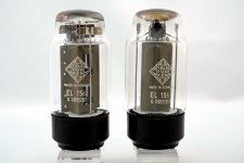
hello, 5pcs EL156 for sale, used, original Telefunken from the glorious golden tube years, measured with Neuberger 370 *, all PCB's and documents for Experience PPP power amp 100W (changed to original 10 pin Y10A socket) on request. Original photos to follow! shipping worldwide (except russia and ukraine !!!)

el_156.jpg


U1000907 145mA
U1000907 140mA
U0301807 140mA
U0301807 135mA
U0301807 135mA

Batchcode.jpg

el156-3.jpg

Attachments

cosinus - a 4way dipole speaker

Inspired by Siegfried Linkwitz and Rudolf Finke i started a new speaker-project - a 4 way speaker, full range dipol, working title: cosinus

Why dipole? Because of the acoustic energy radiated in to the room - to see and show the differences i did some simulation using "Boxsim".

Attachment 1:
shows the level on axis (upper line) and the energy that is radiated into the room for a well buildt classical 3way Bassreflex speaker

Attachment 2:
shows the level on axis (upper line) and the energy that is radiated into the room for a 4way dipole speaker, similar to the one Siegfried Linkwitz has buildt

The line for the energy describes the sum of the acoustic energy under angle radiated in to the room - and is therefore a good description of how the speaker sounds. To make it a little clearer, let us have a closer look to the angles 30, 60 and 75degrees. Just looking at the radiation to the listeners direction they ideally should be down in level as the function the cosinus, so 30° should read about -1.3dB, 60° should read -6dB and 75° should read -12dB. The following Attachments show that the dipol speaker comes a lot closer to that ideal radiation under angle than the classical speaker construction.

Attachment 3:
classical 3-way speaker

Attachment 4:
4 way dipole speaker

Attachments

  • Energie-Frequenzgang klassischer 3-Wege Lautsprecher.png
    Energie-Frequenzgang klassischer 3-Wege Lautsprecher.png
    80.8 KB · Views: 558
  • Energie-Frequenzgang 4-Wege Dipol.png
    Energie-Frequenzgang 4-Wege Dipol.png
    59.4 KB · Views: 552
  • Rundstrahlen klassischer 3-Wege-Lautsprecher.png
    Rundstrahlen klassischer 3-Wege-Lautsprecher.png
    32.2 KB · Views: 543
  • Rundstrahlen 4-Wege-Dipol.png
    Rundstrahlen 4-Wege-Dipol.png
    33.8 KB · Views: 548

Class AB amplifier issues. Simulation multisim

Hi guys,

Currently i'm designing an AB amplifier just for fun, i build an amplifier before based on STK 084 module (over 20 years ago) . Well now im building a new design which i simulated in multisim. I read the book of amplifier design of malestrom. But i'm having some difficulties. When i simulate my circuit i get a strange ripple on the positive half wave of the audio signal. I have no clue what the cause is. Is there anyone who knows what causes the ripple? Underneath the schematic and simulation output. I really would appreciate help!! I already made the PCB boards so i hope this can be solved by adjusting component values.


1651185011151.png


1651185113463.png


Kind regards,
Geert

LTSPICE - Simulating variable load?

I would like to work on a discrete regulator circuit, and an important criterion is how well it does when the load (e.g. a DAC or pre-amp circuit) alters its power use rapidly (typically at audio frequencies (*)).

Any suggestions as to how I represent such a load in LTSpice?

BugBear

(*) yeah, I know, some extreme class-A amplifier circuits don't do this.

Solid State Kits

So seems due to a health issue I’ve been sidelined for alittle bit. So, I figure maybe I’d build an amp. Just curious what you guys think are the best sounding amps. I do know how to solder. I can get help for a really excellent retired tech. Haven’t built an amp since 1978 or so when o was a little kid. I was thinking about the ACA and trade out the signal resistors for Caddocks. Maybe upgrading the caps alittle also. My only concern is 15 watts mono are enough to drive speakers with some authority. I have a Mac MC250 that I had restored by Atma-Sphere. How would this amp compare to that? Is it easier to build separate boards to experiment with? Possible to geek out a few more watts? Any other kits that would be better? Thanks for all the input. I do appreciate it.
My system components are as follows.
Atma-Sphere MP-3 pre
Bel Canto Streamer Dac
Klipschorn speakers 105 Db.

My DIY speaker project

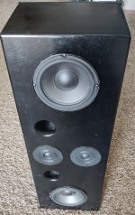
This is my project I did, done while I was in college and on a budget. As such I had little tools and workspace but given the means I think it came out well. I hope to continue to expand and grow this project because it was a lot of fun. For starters this project uses a set of 8in Alesis full range speakers and two 4in tweeters (from the previous full range). I harvested these from old bookshelf speakers. The box I designed and built myself out of particle board. For the amp I used a car amp and then to be able to get media to stream I used a "Up2Stream Pro V3 - Multiroom Wireless Receiver Board (No Amp)". I then built it in such a way that it actually uses an ATV battery, providing at minimum 10 hours of use before needing a recharge.
Speaker Front.jpg
The idea I had behind this was to get it so the speaker was not just a speaker for in the house, but more importantly one that could be used on the go. I realize this is significantly larger than typical portable speakers, but eventually I will build smaller.
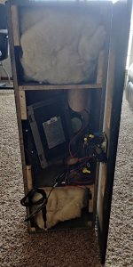
Speaker Inside back.jpg
For the two full range drivers I ported using cardboard tubing, and then proved insulation in each speaker chamber. This came about after some trial and error and just playing around with what sounded better and reduced interference.
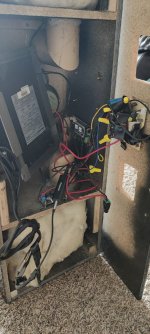
For the wiring like previously stated I used a car amp that allowed me to separate into left and right channel and also full range and high range. This amp was the second choice of amp I made because I had issues with several amp boards being overloaded due to wiring issues. The Arylic board I used I have done things with their products in the past and liked how I would get several input options: from Wi-Fi and Bluetooth to aux line in. In order to make this board work I used a voltage converter to reduce from standard ATV battery 12V to 5V. I encountered a number of problems from there, one of which was some feedback coming through the ground. I found a ground loop Isolator significantly reduced this problem to the point it is only noticeable at very high volumes.
Speaker inside boards view.jpg
On the box I did go for the black because I was hoping for a piano black finish, but due to time constraints and poor working areas, I did not get the high gloss mirror finish I was hoping for, but it still turned out okay. I have been using this build for over a year now and have had a blast. At first, I heavily used the Wi-Fi and Bluetooth features of the Arylic board, but now that I am in a more permanent space, I have linked this speaker via auxiliary cable with another arylic product to provide a more immersive sound in all points of the room. I use it with music, movies, and TV. What do you think? What ideas do you have?

Speaker Side.jpg

Reflections

Hi there,
Bear with me as I am a total newb on these topics..

I am using a 2.1 system. PC ---> AVR ---> speakers. Using JRiver for audio. My left channel appeared to be louder but the meter says they are equally as loud I tried lowering it by 0.5 dB increments but it never sounds right across different tracks I know well. I could be wrong but I think the wall reflections close to the left channel might've been causing this. The wall from the right channel is much further.

According my calculations the left reflection arrives at 7.55ms and the right reflection arrives at 15.55ms. I added 8 ms of delay to the left channel and it seems to me the extra loudness is gone, the sound is more balanced/coherent now and the imaging is solid as I move my head around the "sweet spot". Before it was all over the place.

So my question is if I add a slight delay to the left speaker, the reflection comes in later but so does the direct audio from the speaker. Is this the correct way of utilizing DSP?


Room.jpg

Additional changes for a pair of Maggie 2.7 qrs? I'm about to pull the covers off to fix some delaminated wire

This is my first and hopefully last attempt at fixing my new speakers delamination and wire starting to come off( i bought them broken about a month ago) is there any other quick mods like capacitor upgrades or anything that can be done while they are apart that dont cost a fortune? I thought since im pulling them apart anyway now would be the time to do them-any mods that you know that work universally or anything along those lines would be appreciated.

AC30 Grounding Rework

I have built my own 300b amp, and obviously spent a while considering the grounding.
I have just been given an AC30 to repair, and have done so, but am appalled at the grounding approach and associated noise.
I was just wondering if anyone had rerouted the earthing on an AC30 to reduce noise, including isolating signal and chassis earthing, and what their experience had been?
Many thanks

Inverting Subs - Worth It for Cooling?

Hi, all...

I think I have a full picture of all the advantages/disadvantages of standard versus inverted mounting, but I've never found a satisfactory answer to this question:

All things being equal on a sealed box, do you think it's worth inverting the subs solely for the benefit of keeping the voice-coil/motor cooler?


I mean... it's has to get hot in that sealed chamber, right? I know it varies based on the size of the subwoofer and the size of the chamber, but how hot does it get in there? Does it approach a level where it really 'matters'?

An experience that makes me ask: I had a 4th-order bandpass enclosure for four subs, all of which were individually chambered (to the same specs). Two of them were mounted in the standard cone-out fashion, and two of them were inverted. Well, guess what? When I took the woofers out of the box, two of them had seized (the standard mount) and two of them were fine (the inverted mount). It could be a coincidence, but I can't help but wonder as I build my next sealed box.

I would appreciate any insights you might have. Thanks!

SPL Calibration ideas with no reference

Obviously national labs and acoustic companies have invested millions in SPL calibration and we can't hope to compete at that level. Still, I'm trying to think of some easily reproducible "thing" that could get within 2-3 dB or so. Ideas that come to mind are a certain size and weight paperback book being tipped over onto a flat surface. A specific ball bearing dropped onto a granite surface plate. It has to be something that a person could reproduce using nothing more than a verbal description and uses commonly available materials. An impulse is fine, since we have sound cards and can look at the waveform, though the frequency should be "easy" for available microphones. This is a brain teaser so if your first thought is "impossible", keep thinking. There's the thread on spark gaps, but that's only doable by those with some electronics skills and is better for frequency response rather than absolute level.
  • Like
Reactions: TNT
Projects by fanatics, for fanatics
Get answers and advice for everyone wanting to learn the art of audio.
Join the Community
507,906
Members
7,893,229
Messages

Filter

Forum Statistics

Threads
406,471
Messages
7,893,229
Members
507,906
Latest member
JoseCR