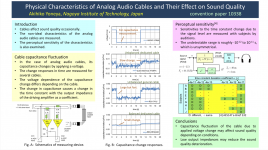
Found an Engineering Brief from the last (virtual) AES convention in Vienna. The author posits that interlink capacitance is modulated by the signal level. Since that capacitance forms a low pass with the load impedance, a varying capacitance has an impact on the reproduction. He states that this is a possible source of 'cable sound'.
I'm not sure I fully understand the measurement and testing method, and the audio is pretty much undecipherable, but what do you guys think about this?
Jan
I'm not sure I fully understand the measurement and testing method, and the audio is pretty much undecipherable, but what do you guys think about this?
Jan
Attachments
Something odd here because RG-174 uses a polyethylene dielectric. Audio levels are several orders of magnitude below the breakdown voltage.
As it is coaxial, you are not getting mechanical changes, which are possible with figure of 8 speaker cables due to motor effects.
RG-174 is an excellent RF cable, so any capacitance modulation would be noticed as intermodulation unless it was a very low frequency effect.
As it is coaxial, you are not getting mechanical changes, which are possible with figure of 8 speaker cables due to motor effects.
RG-174 is an excellent RF cable, so any capacitance modulation would be noticed as intermodulation unless it was a very low frequency effect.
Hi,
Seems this guy is using about a two volt square wave to test. As most of our equipment is topping out at about 1 volt, seems likely the test may be exaggerating the "problem". FWIW
Seems this guy is using about a two volt square wave to test. As most of our equipment is topping out at about 1 volt, seems likely the test may be exaggerating the "problem". FWIW
There is no way to make sense of the figures.
Schematic:
The cable under test has an end connected to nothing but a "dummy socket".
Transfer function, a box and one can see a s variable.
Schematic:
The cable under test has an end connected to nothing but a "dummy socket".
Transfer function, a box and one can see a s variable.
I see values of 0.01 pF/m - it seems like measurement noise for me. I mean I think such minor capacitance change affects no more than a Moon phase or footsteps in the room. It is from the first sight.
Though...
If these measurements are done right then let's take 1 m of a good cable:
0.01 pF / 200 pF = 0.005 % change. It may have value.
It is hard to hear such a small distortion (or impossible in most of the setups) but I think it can be possible in some cases.
Though...
If these measurements are done right then let's take 1 m of a good cable:
0.01 pF / 200 pF = 0.005 % change. It may have value.
It is hard to hear such a small distortion (or impossible in most of the setups) but I think it can be possible in some cases.
Last edited:
Yea microscopic levels. And what exactly is it doing, do they say its adding THD, have they measured the change in signal or just in the capacitance? This time constant thing seems a deliberate misleader. Where did they get that transfer function? The capacitance forms a low pass filter, a change in capacitance changes the filters freq, thats all. And that freq is in the Mhz and canges .005%.
There listening test set up makes no sense. The transfer function uses S transforms on a digital signal? Thats like putting an analog filter right before the DAC? And when someone says 10 fento seconds makes an audible difference to anything I call BS. Are there any peer reviews?
Last edited:
Passive intermodulation (PIM) issues in cables and other components are well known in the telecom/RF fields, and there are proven techniques to measure it with exquisite sensitivity.
The author of the paper does not seem to be aware of these techniques, and uses his own conventions and methods, which do not look trustable or inspire confidence.
Passive Intermodulation (PIM) | Anritsu America
https://www.kaelus.com/uploads/Kaelus/4c/4c19dc3c-243e-40e4-9d07-8b35edac8ed4.pdf
etc, etc.
Anything about audio freqs? These papers are all about RF, where its obvious a cable that varies C and thus its characteristic impedance may cause problems.
The graphs show step changes in capacitance, which does not fit with very low frequency dielectric absorption. Anything fast will show up in RF PIM tests, which measure down to the -150dBm level.
I think that there is a method error.
I think that there is a method error.
I have no basic problem with measurements shown, which besides are a shoot in his own foot: he proves "there is" a change, but also that it is microscopic and to boot near the measurement noise floor.
2) he also only claims a *capacitance* measurement, whose effect may or may not be inside the Audio band.
If outside, its importance is nominal or trivial but has no practical effect.
3) nothing he shows justifies the listener sensitivity to the presumed change, he just claims there was a detectable change.
Nobody can measure or detect *capacitance* changes by ear, but their effect on audible signal.
Where is the test design and protocols?
Was it a double blind test?
Very much doubt so, and in such case placebo effect may make listeners "hear" what is not there.
Apparently a 10kHz tone was played, somehow a 1kHz squarewave modulation was applied, a time constant was involved (I see no mention of preamp output impedance and cable capacitance) , such a time constant was within the audio band, so 10kHz tone was modulated by said squarewave.
But I am only imagining the listener side of the experiment, see no clear explanation of it so I can only "design" what I would have done.
This looks similar to a Homeopathic drug test, where half the patients get plain water (placebo) while other half takes "Homeopathic drug" which chemically is indistinguishable from plain water, and so is also placebo by definition.
And yet "results" are "derived" from such test.
Peer reviewed? ... sort of, it was presented at an AES convention.
But we do not know what did AES Members say about it.
Apparently they have a 1 kHz sine wave of which the level is switched between two values and a 10.05 kHz tone. Presumably the 10.05 kHz is what they use to measure capacitance with.
I'm amazed by how large the measured changes are. +/- 0.01 pF/m at 100 pF is a +/- 100 ppm change, while the -140 dBc measured during PIM tests means that the intermodulation products are only 0.1 ppm of the test tones. The RG-174/U cable can basically be regarded as a capacitor with a good and very thick dielectric, and audio frequency capacitor distortion tests normally also require very accurate equipment, as long as it is not a ceramic class 2 or tantalum capacitor that's being measured.
It could be that the 1 kHz just drives their test circuit slightly into compression, but then why would there be different results for different cables?
The time scale is from 0 to 20 seconds, so if the effect is real, it is apparently a very slow effect. That could explain why it doesn't show up in normal harmonic distortion or RF intermodulation tests.
Last edited:
It seems that the effect is real. Apparently, his reasoning is that varying capacitance varies the low pass cutoff frequency formed by that cable cap and the load. He mentions that the effect is largest with heavy (low impedance) loads. That doesn't seem to make sense, maybe he means the source impedance.
But you need a large cable cap to get a low pass inside the audio band to begin with, and then it varies by 0.01%, and that should be audible? I do not buy that, especially because there is no detail about his listening tests. It may be measurable, but not audible.
BTW The low value with the RG174 may also be because that cable was measured in balanced mode so there may be some cancellation effect.
It reminded me of a presentation (also AES) about capacitance variations in film caps due to electromagnetic constriction. Measured with a laser interferometer, it was found that the cap diameter varied by about one film molecule diameter with a 10V signal.
This type of presentation (poster session) is when someone, most often a student, pastes a large poster against a wall and is given an hour to pitch it to passers-by in the venue room or hallway. Not peer-reviewed in advance. Often they are hair-brained but once in a while there's a great gem among them.
Jan
Last edited:

If it is load dependent and not an effect of the load on his test setup, that is pointing at magnetic effects....He mentions that the effect is largest with heavy (low impedance) loads. That doesn't seem to make sense, maybe he means the source impedance....
Jan
RG-174 has a steel ie ferrous stranded inner conductor. At sufficient current the strands will compress, while the braid is forced out. Both reduce capacitance.
At high currents heating will also affect the results.
So many variables to consider.
This might be a consequence of dielectric absorption, which is going to affect the surface layers of the dielectric in a voltage dependent manner, perhaps modulating its effective thickness. But the values are tiny, 0.01pF/m is at the 100ppm level for a change in capacitance for typical cables, and capacitance is usually already "negligible" as cables are driven low-impedance and time constants will be comparable to the travel time along the cable, in the 10's or 100's of nanoseconds.
Put another way the cable, if only terminated in high impedance, may have a resonance in the 10MHz to 100MHz range whose frequency could change on the order of 100ppm by this effect, although such resonance may be very well damped if the source has a resistor around 100 ohms, as many do.
Measuring the resonant RF frequency of a cable length while varying the DC voltage on it would be a good way to measure this effect, if its real. In fact you could do this directly on a capacitor using the same dielectric.
Perceiving a time constant change of 10^-11 seconds is equivalent to detecting a 60ppm change to a 1MHz tone, or a 60ppb change of a 1kHz tone.
> using about a two volt square wave to test. As most of our equipment is topping out at about 1 volt
I build a dog-porch and want to test it. If it does not quickly collapse with 10 dogs, it is probably safe for 5 dogs long-term. Testing with 2V may be quite valid even if most signals are 1V. (Many hi-fi are higher!) We would like "some" trend testing to know if a distortion reduces with signal level. It usually does but there are significant exceptions.
(this time) Not a student. Akihiko Yoneya, Associate Professor, Nagoya Institute of Technology, Nagoya, Japan
I can not find him on NIT's main site but there are language and DNS issues.
Poster page: Virtual Vienna Convention
I do find Yoneya on ResearchGate, and on another site which seems to be the Nagoya Researcher Database.
Akihiko Yoneya's research works | Nagoya Institute of Technology, Nagoya and other places
Details of a Researcher - YONEYA Akihiko
Me, I can't make sense of that poster.
AHHHH.... there is an 8-page paper. Peer reviewed.
Author: Akihiko Yoneya Affiliation: Nagoya Institute of Technology
AES Convention: 148 (May 2020) Paper Number: 10338
Publication Date: May 28, 2020 Subject: Posters: Loudspeakers
Permalink: AES E-Library >> Physical characteristics of analog audio cables and their effect on sound quality
$33 (>$4/page!) for non-members
I build a dog-porch and want to test it. If it does not quickly collapse with 10 dogs, it is probably safe for 5 dogs long-term. Testing with 2V may be quite valid even if most signals are 1V. (Many hi-fi are higher!) We would like "some" trend testing to know if a distortion reduces with signal level. It usually does but there are significant exceptions.
.....This type of presentation (poster session) is when someone, most often a student, pastes a large poster against a wall...
(this time) Not a student. Akihiko Yoneya, Associate Professor, Nagoya Institute of Technology, Nagoya, Japan
I can not find him on NIT's main site but there are language and DNS issues.
Poster page: Virtual Vienna Convention
I do find Yoneya on ResearchGate, and on another site which seems to be the Nagoya Researcher Database.
Akihiko Yoneya's research works | Nagoya Institute of Technology, Nagoya and other places
Details of a Researcher - YONEYA Akihiko
Me, I can't make sense of that poster.
AHHHH.... there is an 8-page paper. Peer reviewed.
Author: Akihiko Yoneya Affiliation: Nagoya Institute of Technology
AES Convention: 148 (May 2020) Paper Number: 10338
Publication Date: May 28, 2020 Subject: Posters: Loudspeakers
Permalink: AES E-Library >> Physical characteristics of analog audio cables and their effect on sound quality
$33 (>$4/page!) for non-members
Attachments
Last edited:
In the references there's also an Engineering Brief from the 120th Convention, where he made a similar case of changes in headphone cables due to the current in the cable instead of the voltage on the cable.
For some reason I can't find that in the AES E-library.
Jan
For some reason I can't find that in the AES E-library.
Jan
My problem is I don't understand the test setup.
What is the fall and rise time of the test pulse?
If these are in the ns area, then the cable should have a source and load impedance that is equal to the cable impedance?
What is the fall and rise time of the test pulse?
If these are in the ns area, then the cable should have a source and load impedance that is equal to the cable impedance?
In the references there's also an Engineering Brief from the 120th Convention.... For some reason I can't find that in the AES E-library. ...
Perceptually Affecting Electrical Properties of Headphone Cable — Factor Hunting Approach
Author: Yoneya, Akihiko
AES Convention: 147 (October 2019) eBrief:532
Publication Date: October 8, 2019
Permalink: AES E-Library >> Perceptually Affecting Electrical Properties of Headphone Cable — Factor Hunting Approach
He needs a proof-reader. In this paper "Audio Technica" is repeatedly given as "audio-technical". There are passages which do not seem to make sense in English but may be Japanese idiom.
- Home
- Design & Build
- Parts
- Signal-dependent cable capacitance change