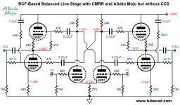
TDA1541 and others current out DAC tube out stage.

Hello! I would like to know your opinions on this output stage that I am attaching in the photo.
The only difference is that my current psu can only supply 230Vdc and not 270Vdc.
I must say that the sound result is amazing!
Any advice from you would be precious to me!
Granzie in advance.
Antonio.

Attachments

  • IMG_20220319_215722.jpg
    IMG_20220319_215722.jpg
    409.3 KB · Views: 614

How to build the perfect ported cabinet. ...

After having fooled around in this hobby for more than 25 years, I would like to share the "rules" I follow when I build two-way ported loudspeaker cabinets.

1. The first I do is to choose a midwoofer with Qts around 0,30 for standmounts and around 0,40 for floorstanders, that seems to be the sweet-spot. And for midwoofers I prefer motors with copper above and below the air gap (Seas Excel, Scanspeak Revelator), not inside the gap (Satori, Audio Technology, Wavecor). Midwoofers with copper inside the gap may sound superior in the midrange and in the lower treble, but I my opinion they lack punch and power in the bass and lower midrange. And I like the midwoofer's Mms to be no lighter/heavier than 7-8 cm2/gram, that is another sweet-spot that goes well with the Qts.

2. I then use some software to estimate the cabinet volume and port tuning, aiming for a system-Q around 0,70. The cabinet can be larger, but not smaller than 0,70. If space permits, I like the port area to be 30-35% of the midwoofers Sd. And I like to place the round(!) port on the front. The port opening inside the cabinet should be placed on a small baffel. The inside opening schould be placed in a golden ratio distance from the top and bottom of the cabinet.

3. And then the time consuming work begins. I know you can add stuffing inside the cabinet to balance the port response and to damp standing waves, this is a quick and easy fix but in my experience, the less damping inside the cabinet, the better. Lining the walls with ¼" wool felt is ok but even the slightest amount of volume stuffing almost always lead to a less lively and less open and less powerful loudspeaker. So I never stuff. Instead I build the cabinet with angled reflectors at the top and bottom, with lots of non-symmetrical shelf-braces in between, to break up the standing waves without choking the driver/port.

4. Most of the backwave energy will escape through the port and cone, that is how a ported enclosure works, and I don't want that sound to be coloured by vibrating panels making the speaker sound boxy and woody. For the walls I use two ½" thick birch plys in a CLD construction with a flexible one-component marine adhesive sealant, with three ply layers for the baffle. I prefer the stiffness and "sound" of birch ply to MDF. This birch ply CLD, in addition to all the bracings in #3, adds enough stiffness and damping to make the cabinet dead enough. And I aim for a total mass of the cabinet 1200-1500 times the midwoofer's Mms, I don't want the midwoofer to be able to move the cabinet.

5. I always make the cabinet as deep as possible. In my experience, a midwoofer needs a minimum of 35cm distance to the cabinet's back wall. I don't know why but midwoofers always sound better in deep cabinets.

6. I always remember to test the finished loudspeaker using an amplifier with a high enough damping factor. It is easy to mistake an underdamped midwoofer/amplifier combo for a badly tuned ported loudspeaker. Even the world's best SET amplifier can make the world's best loudspeaker sounding like a boombox, if the two don't match. For SeasExcel/ScanspeakRevelator Qts 0,30-0,40 midwoofers with 7-8 cm2/gram Mms I prefer BJT amplifiers, by the way, these type of midwoofers need – and deserve – power!

So, that is my "handbook". It would be interesting to hear what others may think.

Internal wirering for a waffle maker?

My loved Waffle Maker stopped working. Root-cause was a few wire that broke.

So, what kind of wire would you use internally in a waffle maker?
  • Its hot ( dont know how hot, but hot)
  • There is oil and fat leaking into every part, so wire must be resistant to that.
I have some stanard PVC-wirering, some silicone and some unknown fibre-protected wire.

Any ideas?

Kind regards TroelsM

Sad...

I can't stress enough how much i looked for these transistors even as second hand as they are and how sad the new datasheet makes me feel...I wonder ...what's better than these today?

Attachments

  • 20220418_080410.jpg
    20220418_080410.jpg
    444.5 KB · Views: 475
  • Screenshot_20220418-075835_Word.jpg
    Screenshot_20220418-075835_Word.jpg
    104.2 KB · Views: 473

NAD 3400 & 7600 Parts and remote wanted

Hi

Looking for missing knobs for my 3400 amp. The small square ones, for the frequency selector between bass and treble pots.
Also misses those round black and green plastic knobs.

Original remote if any one will sell.

Rack mounts for monitor series.

Front plate for the 3400 & 7600.
Both mine has scratches and bent sides.

I'm in Norway

Attachments

  • IMG_20220311_091901.jpg
    IMG_20220311_091901.jpg
    172.3 KB · Views: 149
  • IMG_20220311_091916.jpg
    IMG_20220311_091916.jpg
    187.1 KB · Views: 139
  • IMG_20220228_130239.jpg
    IMG_20220228_130239.jpg
    275.3 KB · Views: 139
  • IMG_20220223_223819.jpg
    IMG_20220223_223819.jpg
    257.2 KB · Views: 205

Modulus 86 CHEAP build

After weeks of research Ive decided to build a stereo amp based off of the modulus 86, but it had to be cheap. Really cheap. I decided to disassemble and recycle an older amp to help cut down on the number of purchased parts. I picked up a sonamp 260 on ebay that was in bad shape. It had been dropped and had a lot of damage to the boards. Perfect candidate. Unfortunately, the transformer put out far more voltage than i could use, so I decided to go ahead and try a meanwell I picked up for $15

Attachments

  • IMG_20220321_190801095.jpg
    IMG_20220321_190801095.jpg
    248.3 KB · Views: 340
  • IMG_20220322_094048190.jpg
    IMG_20220322_094048190.jpg
    370.4 KB · Views: 357

When not to use low leakage KL?

Hey all. I'm looking for a good choice to replace all the Nichicon FG capacitors on my amplifier output boards (while the sound is good, it's just too warm). This is a Class AB amp circuit. While looking at different choices and researching caps, I found this Nichicon KL low leakage cap. Would anyone feel that there should not be a place to use this specific cap?

I did come across another post about Nichicon VX, KZ and FG caps all being very low leakage, which supposedly was the reason for the excellent bass response.

The KL caps are physically sized very close to the FG caps (in some cases the same size). They also have much higher ripple current specification then other caps (even KW which is already has a high ripple current spec).

I have been trying to read as much as I can on "low leakage" and the consensus is that most modern caps are already considered low leakage. However, it would seem this KL takes things further. Best I can tell, low leakage is absolutely recommended on precision measurement circuits or high DC decoupling caps. But are there any other reasons NOT to use a low leakage cap such as KL?

I do know that it is not recommended to use low impedance caps in an analog section, but these are not listed as "low impedance" on the Nichicon datasheet.

Alternatives that I'm looking at are 105 degree VZ (worst ripple current specs), KZ (if I can fit them) and KW.

Listening area inside of a 20hz horn?

I have been dreaming of building a theater/listening room where the room itself is the horn. For the sake of simplicity of construction it would be a slowly expanding conical horn with rectangular cross section, where the walls and ceiling would expand out from the sound source at whatever flare rate is appropriate for loading the drivers down to 20 hz, and terminating wherever a good sized listening area is achieved. The entire rear wall would be a very deep acoustic absorber; contemplating the use of wood chips on the order of 6 or 7 feet in depth, contained behind wire mesh, a layer of foam, and fabric.

Thoughts?

Opinions on Mods to FF85wk

I am using ff85wk in Planet 10's great uFonkenwk. I'm hearing a little bit of harshness and would like to do something. Due to financial constraints and/or
lack of skill to do it myself, I am unable to do the enable treatment. Would I be better off leaving them stock or would I at least see some benefit with one or two light coats of Mod Podge? Please understand this is in no way a put down of Planet 10's time consuming process. Thanks for any suggestions.

FS Big DIY tube lot 450+ tubes $250

I have a big stash (450+) of great DIY suitable tubes. All of these are useful for audio and/or boat anchor applications. No useless crap! Lots of 12v, loctal, top cap, etc. Examples include 1625, 6080, 6159, 2e26, 12j5, 12sn7, 12sl7, 7b4, 14a4, EL39 etc. etc. etc. The spreadsheet has some info. Most tubes Are NOS in box, they do not have any additional labels except maybe the brand. Ones that are labeled NB means no box or reboxed. Some of those I know are actually NOS so I've labeled them as such. There are a few tubes that are known to be used but have tested values on the packaging. I've labeled them "Tested." Other than those, none of them have been tested although they are all supposed to be good tubes according to the sellers over the years. Take that for what it is worth...

I want to sell this as a lot so I've put a good price on it for DIYaudio folks $250. I'm partially disabled and so they will need to be picked up at my home in the DC area. I'll bump the post from time to time...

Attachments

  • Like
Reactions: Gill.T

Mar-Ken 12p with side vents

Hello DIYers,
Hope you can help. I’ll make it short. I have the 10p in a Pensil and a 12p in a 19L Base Reflex which does not impress me much. I love the Pensils, bass is enough for what I listen to. I would like to find a better (imaging, detail, finesse, soundstage) enclosure for both. No SuperPensil 12p or FHXL since space will not allow it but would like a floorstand(10p or 12p) and a standmount(10p or 12p). I was thinking of the Mar-ken with side vents (Dave's design) standmounts or MA 12p in a Juliet or CGR Mar-Ken 12p. and the Mar-ken 10p floorstand.
What would the Mar-ken with side vents (Dave's design) standmounts bring over the Pensil? Would the Mar-ken with side vents bring enough bass to the table? What do you think would be the better box for the 12p?
BTW The speakers will be fed with a Finale 6watt EL84 tube amp.

Thanks

Remote IR stopped working? Wadia 860

Looking to debug a problem with a Wadia 860

The Remote Control no longer functions? - both the original remote and a universal remote.

Before opening the lid I thought I would ask some questions....

Background -
Original owner - been working flawlessly for 15 years, has not been moved or fallen.

Does the IR receiver occasionally fail in these things?
Is there someway to test? - (have a decent Fluke Multimeter)

I've done the simple things, check batteries, clean receiver

There is not much support from Wadia these days - and the front buttons on the unit only control track advance, volume and opening the tray (which allows it to still function) but you cannot control the source inputs, programming, phase, repeat and some other functions.

Thanks for any guidance

Various 1stW Clone related parts for sale

SOLD


In the process of building (and learning about) some F6 monoblocks, generated a passel of parts I don't need anymore.
Asking $150 (incl. shipping). Due to weight, US only sale. If in the Denver area, $100 and I'll drop it off somewhere.

Pictures attached.
List includes:
2x Hammond 1182G18 (18VAC secondaries, 225VA)
2x GBPC12005 12A bridge rectifiers (12A)
4x GBPC2502 25A bridge rectifiers (25A)
3x diyAudio PSU diode boards; blank, 1 set of boards is split
1x diyAudio PSU filter board; blank, split
2x diyAudio PSU filter boards, built w/ 35VDC caps, 60kuF per rail
6x SL15 thermistors
1x Schurter 4304.6090 IEC power module
2x 4Ux300mm heatsinks (non-UMS, untapped)
4x 2mm aluminum Mini-Dissipante 23/300 covers
2x 23-250/300 base for Mini-Dissipante
4x modushop puck feet quad
2x Dissipante hardware kits
1pr. 0.5m Kimber PBJ RCA interconnects
20x 0.25" PCB quick connect tabs
var. power busses
var. zener diodes
var. quick connects

will not separate as I want to get rid of this stuff but not via landfill.

Attachments

  • IMG_0037.JPG
    IMG_0037.JPG
    1 MB · Views: 119
  • IMG_0038.JPG
    IMG_0038.JPG
    784.7 KB · Views: 107
  • IMG_0039.JPG
    IMG_0039.JPG
    866.9 KB · Views: 108

MJR7-Mk5 by Renardson

Hi

I try to build Mike Renardson´s MJR7-mk5 amplifier. I made my own board design but someting is wrong. I have now tied to find the problem, butt no sucscess.
The 2A fuse bloves when i power on, but not a 2.5A fuse. With a 2.5A fuse the R13 gets extremely hot. If I messure without T6 and T7 connected I get 40V at every point around Vr1. The rail are 67V.
I staring me blind at this so I can´t se the problem. Can someone check my drawings?

Attachments

6AU6 Circuit

Before anyone makes fun (and I see many doing so here sadly) I am a tube novice, grew up on germanium transistors and just never felt the need to understand tube circuits.

I have a circuit built (using an apparently well known and proven circuit) based on 6AU6 as a pre-amp. Its fed by +/- 30V, Mullard tubes and built on a PCB.

It works, driving it with 50-100mV 1kHz tone it's gain appears to be around 5, which is fine for my need. Now, without connecting any external source to the input (across 1R35 in the circuit below) the output is stable and hum/noise free. However connecting anything to the input (ground or signal side) creates a very high 50Hz hum. Even placing a direct short across the input the hum is present, though the 1kHz tone is killed. I tried shorting to signal ground and chassis ground and then bridging chassis and signal grounds, same.

I "feel" the input impedance is somehow compromised even though there is a 4k7 resistor, and that the actual impedance might be very high.

I cannot figure the circuit so if someone can assist in indicating the likely input impedance and what I need to change to increase/decrease the gain. Any pointers as to why this hum occurs will also be appreciated.
1650727249618.png

1980s Peavey Ultra HiFi Constant Directivity Sp3

It is so very interesting that the original Peavey Sp3 Cabs with the original Eminence woofer
(Very similar to the Klipsch K33) and the 22a (aluminum version) on an 800 hz ev cloned Keele style horn just kicks *** with the original xover and some CD horn eq.
Sure it cuts off around 80 due to the very short bass horn
But boy does that horn ever seamlessly integrate with that Keelish 800hz horn off the 22a driver.
I think Earl Geddes would appreciate how seamless this is.
I know a lot of us have played with the Sp1 (a clone of the LaScala) but I have rarely heard of anyone playing with the old sp3 which is a clone of the JBL perkins type midbass unit.
True hifi here guys smooth as a babys ***. I will try to get some plots up soon. Heads up guys this is a whole lot of great cd speaker for very little money. Impressive. Add Subs and enjoy. Remarkable. Also worth pointing out that Peavey CH-1 500 hz horns and CH-2 800hz horns are much much underated. Really these are Keele style EV horns. Agreat era for horns imo. I am pleased

Dayton Audio OmniMic

My Dayton Omnimic isn't giving the same results as my other calibrated microphone running JustMLS (LspCAD) and I'm pretty sure it's the Omnimic that's not working properly.

I've tried everything the guys have suggested over at the partsexpress forum but it always displays a high frequency droop, but I get the impression that partsexpress think it's user error.

Before I send it back to the USA, I just wondered if anyone here in the UK has one that they could compare to mine? I'll happily send it to you and pay return postage. It just seems a waste sat in the cupboard doing nothing.

AC on +V output of dual rail linear regulator supply?

Considering the dual rail linear power supply circuit diagram at the bottom of this page (https://sound-au.com/project05.htm), what might cause the +V rail to have ~30V AC as well as +15V DC, while the -V rail has 0V AC and -15V DC?

i.e. what could cause the +V rail to have an AC component?

I suspect bad rectifier diodes. But those have been replaced (not sure if replacements were good), and the issue persists. Anything else to check or replace, assuming a cheap DMM and no oscilloscope?

dummy load - wattmeter

hi friends,

glad to come back after a long interruption. I start with a smooth project. I have 4x 8ohm non inductive resistances. It gives me idea of an audio dummy load with wattmeter, something like sencore PA81.

For dummy load part, I think of
  • 4 to 8 ohm switch with extra contacts for correct display value
  • thermal switch for fan
  • DC protection warning
  • BNC output

for wattmeter I think of something around AD637.

advices are welcome and if something exist, I don't want to reinvent wheel

Attachments

  • DSCF0929.JPG
    DSCF0929.JPG
    302.5 KB · Views: 192

Any advice on cutting sorbothane sheets?

I bought an 1/8" thick sheet, with the hopes of cutting a few gaskets for vibration control.

This stuff is nearly impossible to cut cleanly, or even cut at all. It takes several passes to even break through to the other side, and then I have to flip it and cut some more. It pulls, stretches, and eventually slices, but it's ugly. At least it's tacky enough to help hold a straight edge guide.

Any tips? I even tried a razor blade (a real one, made for double edge wet shaving).

Distortion Analyzer - Circuit to build

Hi!

I found this Distortion Analyzer circuit diy project.
You will need 4 op-amps (2 dual).
Wouldnt it be nice to be able to checkout
if your amplifier show more or less distortion, after you have modified it.

1.0 Volt AC at output means 1.0% distortion.
Note, you will need a good multimeter, which can measure AC-voltage at frequencies above 400 Hz.

Article:
http://www.ethanwiner.com/distort.html


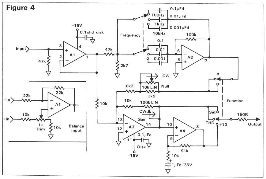
Build a Tape Linearizer and a Distortion Analyzer
by Ethan Winer
This article first appeared in the December 1981 issue of Recording-engineer/producer magazine.


SETUP AND USE

Once you've completed building the unit, plug it in, turn it on, and pray it doesn't blow up! If it passes the smoke test,

take a voltmeter and check each op-amp's output pin - these are conveniently located in the corners of the IC. The DC

voltage should be within a few millivolts of ground; if it is not check your wiring and/or try another IC. Now you are

ready to begin measuring distortion. The first thing to measure should be your sine wave oscillator, so connect it to the

analyzer's input.

Start with the output frequency set to 1 KHz., the function selector to Set, the null pot in the middle, and the analyzer's

gain control at minimum. Now adjust the oscillator to some reasonable output level, and increase the analyzer's gain

control until its output reads 10 volts on an AC meter. (Note that many digital multi-meters do not have a frequency

response that extends beyond a few KHz., so an analog meter is a better choice. Also, since the test procedure involves

nulling, a mechanical meter is much easier to interpret.)

With the full-scale set at 10 volts, switch the function selector to THD, and alternately adjust the null pot and the

oscillator's frequency to obtain the minimum reading possible. Now select the Divide by 10 switch setting and continue

tweaking until you are satisfied that you have completely canceled the 1 KHz. fundamental tone. You are now reading

distortion directly in percent - that is, 10 volts equals 10%, 0.1 volt equals 0.1%, and so on. You will probably find that

due to capacitor tolerances, the 1 KHz. setting is not precisely 1,000 Hz. Again, it doesn't really matter, but you should

make note of the actual frequency to save time in the future. Try the same thing at 100 Hz. and at 10 KHz. (or whatever you

choose), and you'll be an old pro in no time at all.

Circuit:
dist-4.jpg

Budget audiophile speaker cables

I have read so much info on audio cables, my mind is spinning. I've read everything from CAT5 to Home Depot power cable.

Here's my story - I'm running all digital, with active crossover. About 75w per channel max power. I want a fun project with the kid. I'm not looking to buy shares of some Russian mine to come up with exotic materials for 20' of speaker cable.

I have a huge spool of in-wall speaker wire - which is really nicely packaged for making cables. However, I want to do build a set, and listen comparatively.

If this is in the wrong category, apologies in advance. Please feel free to move this thread.

Thank you.

Alpine MRP-M650 Schottky Barrier Rectifier? “SK 2B”

I’m not to familiar with these types of diodes, just wanted a confirmation that it is in fact bad as I am interrupting from the DMM testing, and that I do have the right data sheet for this component so I can buy new ones.

D403/SK 2B: DMM Diode mode shows 0.012-0.13v both ways, from what I’ve read I am supossed to get between 0.2-0.4v one way, all 4 are reading similar.

Also wanted to confirm that I do have the right data sheet, I think I do but I don’t want to just assume.

Half the high&low outputs blew due to abuse and very bad environment conditions. The 4 to the left if looking at board right side up, 4 to right if looking at pic as is, upside down.

Thankyou 🖖🏼

Attachments

  • AB857858-073E-4128-B96F-A7BF227E444F.jpeg
    AB857858-073E-4128-B96F-A7BF227E444F.jpeg
    541.9 KB · Views: 100
  • 7075EEB4-A363-40F7-B44D-29D14CE59EA8.jpeg
    7075EEB4-A363-40F7-B44D-29D14CE59EA8.jpeg
    578.8 KB · Views: 104
  • A1891F6D-21EF-4597-93EB-FE4382F4F1C4.jpeg
    A1891F6D-21EF-4597-93EB-FE4382F4F1C4.jpeg
    637.8 KB · Views: 94
  • CD7D7F3F-486B-4DD3-8523-D21ACFB9A78E.jpeg
    CD7D7F3F-486B-4DD3-8523-D21ACFB9A78E.jpeg
    190.1 KB · Views: 91

Eminence KL3012HO 2-way cabinet design

I have a pair of Eminence Kappalite 3012HO 12" drivers that I wanted to build some compact 2-way monitors (doubling as small PA tops) with. For the CD and WG combo I chose 16 ohm B&C DE250s and Eminence WG10s.

Crossover will be passive, but may use a dual channel plate amp with built in dsp down the road. For now I want to keep it simple and basic.

The question is what xover point and cabinet design would you prefer to use based on LF driver performance data? I would definitely choose tighter / cleaner low end response over output capability.

Anyone have experience with this Eminence driver? It looks and sounds nice from the little bit of listening tests I've done so far in 1.5 cu ft sealed test cabs. I was leaning towards maybe some slight LF driver WG loading to increase lower mid projection outdoors and to align acoustic planes of both drivers for easier xover.

Attachments

  • 20220422_164554.jpg
    20220422_164554.jpg
    213.4 KB · Views: 135
  • 20220422_171050.jpg
    20220422_171050.jpg
    72.4 KB · Views: 133

Altec 1712a Switch ON/OFF Switch replacing

Hey all, this is my first time posting here so excuse my stupidity.

I purchased a couple of Altec 1712a's and I'd like to change the ON/OFF Push Switches which are soldered to the board..

1650592614693.jpeg


1. The Current Switch is a... Schadow TVR NE15 - DPDT. 4A/ 250VAC
1650592118357.png


2. I'd like to replace it with a Toggle Switch that would have to have right angle pins so that i can solder it to the board.
1650592342244.png


I'm struggling to find a toggle switch with right angles pins that's 4A/250VAC

Can anyone help? Thank You

My Invention

Self explanatory I guess -- all but the electromagnets (silver disks)
I picked up a pair of the magnets to experiment with, shocking how powerful they are, and only need a tiny 9 volt wall adapter for power.
The wall adapter is in a powerstrip with a shopvac, push the hold-down where you need it and turn on the power, It comes to life!
Oh boy they are powerful, they miss the iron deck by a little bit here, but they still cannot be moved.

I don't have a link for electromagnets, but there are out there, the cost was very reasonable.


Mags.jpg
  • Like
Reactions: GM and Johno

Computer games

Perhaps some would be interested in a thread for PC games?

I do not have much time for these things anymore, but I just recently purchased Forza Horizon 4 (Ultimate edition).
And I have missed playing racing games, so much fun!
Now I've been having some issues with the entire game slowing down for some weird reason, even though I have more than enough hw to get higher than 60fps with most settings on Ultra. Just found out it may be related to some issues with the ridiculous "Windows Game Mode", hoping I will get it working this evening.

Forza 7 was a big letdown for me, with the homologation limits that I really did not understand, the auto homologation thing that was just horrible, and the game itself full of those annoying loot boxes and whatnot. For some reason buying a specific part would break some kind of rule or limit and it was sometimes a bit difficult to figure out which part was the culprit. If it was fixed in some patch I would'nt know, dropped it like a stone.

Been a big fan of the Civilization series for a long time, had probably over 4500 hours on Civ 4 with BTS expansion. Civ 5 and 6 felt very "unfinished" when they came out, so have sort of lost interest. Hoping that perhaps a future strategy game will be able to catch my attention. Really liked the old Alpha Centauri. And ofcourse things like Masters of Orion 2.

Really looking forward to "Outer Worlds" from Obsidian!
The Outer Worlds
Finally another spiritual sequel to the Fallout series!
Loved Fallout 1 and 2! Fallout 3 and 4 isn't really Fallout, Bethesda has managed to ruin it properly, thankfully they eventually had the sense to ask Obsidian to do Fallout New Vegas, which was a great game.

USB charger

Hello, I am designing a USB phone charger. I want to put this in my PSUs, so I can charge my phones and laptop.

Here is the schematic.

The JD6606 is controlling output through the power FET. According to its manufacturer, it can go upto 20V. However, when I go over 6V DC in input, it stops working.
If I keep it under 6V and put my Samsung Galaxy, it says "fast" charging and consumes 7-8W (output is 5V). I want to reach 12V and 20V to be able to charge my laptop too.

I am thinking to keep Vdd 6V, despite the input on the FET. But I don't know if I have to touch feedback or anything else. Any ideas?

Attachments

  • USB_charger.png
    USB_charger.png
    40.5 KB · Views: 136

PS4 SOURSE

I already know some of you will be laughing.. Im using ps4 for source and spotify. would a streamer make a noticeable difference? if so would I get better bass? better sound stage? louder? have any of you switched from ps4 or xbox to a streamer? Budget £500-£700. I only listen in multi channel 2fronts 2front highs. may one day get rear heights

Making audiophile power cord and have question about using crimping cable ends

Hello!
I have read often diyAudio forum and find lot of useful information, thanks for forum members. Now I have some question for members who have made audiophile AC power cords. Do you use scrimp cable ends sleeves with multicore cables? I know that without is better but with thin multi core wire it is necessary. If the cable is silver plated and plugs are also silver plated is it better to use silver plated copper cable ends sleeves also? Theses silver plated cable ends are available in some audiophile online stores. There will be always some air between cable end sleeve and wire cores left after scrimping, will the corrosion and with air formed sulphide will be problem in some years. Like to make as best power cable as possible. Thanks.

Seas CA18RLY or CA18RNX for floorstander

I want to make BassReflex floorstander with 6" Seas Prestige. My first priority is extended bass response, no matter what size box will be. I'm in mix between Seas CA18RLY and CA18RNX.

Using Hoge's formula I got:
CA18RLY - f3 = 31Hz, Vb = 55L
CA18RNX - f3 = 47Hz, Vb = 17L

Obviously CA18RLY seems like better choice, but Troels Gravensen mention several times that RNX is better for bass, and now i'm confused 🙂

"The CA18RNX is a long-throw, large voice coil variant of the Prestige paper cone drivers handling bass better than the CA18RLY, which holds the classic 1" voice coil."

what do you guys think?

Resistor matching error starting with six 1% resistors

I got interested in obtaining better-than-1% matching of metal film resistors, especially "uncommon" values among the E96 series of standard resistors, that are not offered / are not stocked in the (much more expensive) 0.1% tolerance grade.

I decided I was willing to buy six resistors and pick the best matching pair among them, then discard the other four. So I put together a little Monte Carlo simulation to see just how good or just how bad the results might be. Assumptions built into the simulation
  • Resistors are "100 ohm, 1% metal film" devices. Smallest possible resistance is 99.00 ohms, largest possible resistance is 101.00 ohms
  • Resistances are uniformly distributed; all values between 99 and 101 ohms are equally likely
  • Mismatch between two resistors is defined to be [(Rbigger - Rsmaller) / Rsmaller]
I fired up the computer and performed one hundred thousand trials. Each trial consists of: (a) Generate six random resistor values, uniformly distributed between 99 and 101 ohms; (b) for each possible resistor pair, calculate the mismatch; (c) report the best [lowest!] mismatch of all possible pairs. Results, in ascii .csv format so anyone can slurp the data into a spreadsheet, were:

Code:
mismatch,count
0.00000,13990
0.00010,12335
0.00020,10917
0.00030,9358
0.00040,8251
0.00050,7289
0.00060,6197
0.00070,5345
0.00080,4558
0.00090,3854
0.00100,3301
0.00110,2781
0.00120,2263
0.00130,1926
0.00140,1558
0.00150,1359
0.00160,1047
0.00170,816
0.00180,659
0.00190,536
0.00200,420
0.00210,346
0.00220,253
0.00230,180
0.00240,136
0.00250,110
0.00260,78
0.00270,64
0.00280,36
0.00290,15
0.00300,10
0.00310,8
0.00320,1
0.00330,1
0.00340,1
0.00350,0
0.00360,1
0.00370,0
0.00380,0
0.00390,0
0.00400,0
I made two histogram plots, one with very few bins and another with very many bins. They are shown here.

I have to say, I'm delighted by these results. About once per ten thousand trials, the best match is "terrible", namely 0.31 to 0.40%. On the other hand, there's a 55 percent chance that the best match is "fantastic", namely 0.05% or better. Woo hoo.

attachment.php


attachment.php


_

Attachments

  • histog1.png
    histog1.png
    12.1 KB · Views: 1,146
  • histog2.png
    histog2.png
    14.3 KB · Views: 858

Iron Core coils on a planar magnetic

WEll i posted a measurement Air coil vs Iron core on a facebook group. i measured the actually output from my speaker to see what would happen (dont mention overal distortion its about the difference.)

And i get allot of comments about what i try to do cant be done, you mic is not accurate enough to measure this kind of distortion and i measure wrong, i have to realign the filter etc etc..

in my honest opinion the way i measured it might not give the greatest detail but will show witch coil i would use and witch i wont in a planar magnetic...

Speaker used Planar magnetic bass, amplifier hypex NC400 class D , mic isemcon emx-7150 perfectly capable of measuring what i can even hear.

FR of the 3mH Iron Core and the 3mH air coil.
FR.jpg

Distortion of the AIR coil
dist AIR.jpg

Distortion of the IRON core
dist IRON.jpg

Impedance measurement of both coils since i was told the filter needed to be realigned and the Q changes because of the significant difference in resistance 🙂 0.14ohm..
Green no coil
Yellow Air coil
Purple Iron Core
impedance.jpg
No what baffles me is the enormous added distortion with the iron core, you can even hear distortion riding on the fundamental. not pleasant.

any idea why this is so dramatic >?can it be something with combining it with a resistive load like a planar ? or is the class D amp going mad ? (would be shamefull)
or is it just Hysteresis Distortion, and these coils would suck in any case.

Chaining filters

Hi,

So far I've build a few supplies, where I used lm317 for regulation. Unfortunately, I don't have any equipment to actually see the DC current, so I'm just guessing the outcome.

I'm using a resistor between reservoir and filter capacitors. I've found a formula 1/2PiRC - I either have to limit the current output, or to put a large capacitor bank to get under 1 Hz.
My questions are: would multiple 6800uF caps overstress the diodes/transformer; would I get the same result by using two R/2 resistors with two 3300uF smoothing capacitors? I don't have experience with using choke instead of the resistor.
Any other ways to improve the DC output?

First cycle distortion - Graham, what is that?

First cycle distortion - Graham, what is that?

I have never heard it before.

In another thread I mentioned distortion of the leading edges of first cycles, and called it 'FCD' = first cycle distortion.

http://www.diyaudio.com/forums/showthread.php?postid=373559#post373559

Can you explain? Has music really signals that can be regarded as startup transients? Maybe for slow amp?

Can you give me any reference material?

Free JBL 2202-h pickup only south Atlantia Ga.

I have a working JBL 2202-h and a 2202-h that needs reconeing. I am old, lazy and even when 20 years younger
I didn't like packing and shipping. So the drivers are free if you want to pay $250 for me to pack and ship them or
as I said they are free if you pick up about 20 miles south of Atlantia in Tyrone Ga. Sorry I am not going to the trouble
to make pictures for a free driver.

The Alexander amp - current feedback and opamps

I'm sorry for the esoteric question here, but I asked Analog Devices directly and they have yet to respond. My two questions are about the Alexander Power Amplifier from an Analog Devices Application Note:
AN211
http://www.analog.com/UploadedFiles...211.pdf&fterm=alexander&fterm=alexander&la=en

Just to give a brief heads-up, it is a current feedback-type power amplifier that also uses the power supply pins of opamps to carry the signal in the input section of the circuit.

1) I understand why A2 was added to the circuit (to reduce the DC offset at the output of the power amp). Even though A2 is specified to be a very low offset opamp, how can we be sure that it will contribute a low offset when we are using its power supply pins as outputs (instead of its conventional output pin)? How can we be sure that if we use the output pins themselves of a low offset opamp, they will contribute to a "low offset" of the overall audio amp at its output?

2) The author stated that the two compensation caps (C6 and C7) were originally placed from their respective nodes to ground - then they were later removed from ground and tied together at the output of opamp A1. Did the author have insight and prior know-how to do this, or was it a mere guess and check approach that happened to provide better results?

Amp build for ESLs - F5T vs BA3?

Hello kind and wise sirs, the following problem has been briefly touched upon, but, as far as I could find, in a rather nonspecific manner.

I hope to build an amplifier that will drive low impedance speakers, ESLs, and specifically, Martin Logan Summit Xs. Mr. Pass being the nicest, kindest and wisest guy in audio, using his designs would make me happy.

The speakers impedance curve looks like this:

martin-logan-summit-x-impedance-phase-graph.gif


The impedance goes down to 2 Ohm above 6kHz and touches on maybe 0.7 Ohms at 20kHz.
Sensitivity is rated at about 91db/Wm

As my limited understanding has it, this requires the amplifier to be able to deliver lots of current into low impedance loads.
Also, given the varying impedance, some voltage oomph will be beneficial too? Regarding listening levels, I don't intend to drive them at party levels, they are electrostats after all.

All this leaves me with three options, as I see it:

(as an aside, I already have two 400VA +-24V power transfomers, so this reflects in my thinking🙂

1. Burning Amp 3 with complimentary output stages, 6 deep output stages per side, monoblocks of 5U 500mm cases each for maximum of heatsink
Question: There's a lot of discussion about the source resistors, they are supposed to be 1 Ohm for the 6 pairs. Would there be any benefit for current delivery in going to lower values for the source resistors, given the constraints of heat/power dissipation?

2. F5 Turbo V2 - as Mr. Pass says clearly, greatly improved current delivery vs F5. On a plus, it would be possible to build this in one dual mono 5U 500mm chassis.
Question: How does the output stage compare to the BA3 PP in current capability?

3. Going all the way with an F5 Turbo V3, monoblocks in an 5U 500mm chassis each, transformers paralleled for 800VA.
Question: Is there a tangible advantage over the F5V2 or BA3 for my use case?

Just going by the expected power supply capacity/rating, if my understanding is correct, F5V3 should have by far the highest output potency. Does that mean best in my case? Complexity is also highest though.

The amount of knowledge and support here is amazing. Please advise me kindly or harshly, anyhow, as I am in way over my head, no matter what 🙂

I have parts already for the BA3 (which was my original plan before acquiring the speakers), but having gone all out on the speakers, I really want to do them justice.

Tube input stage - plate choke or active load?

Let's assume a tube with up to 10K Rp such as DHTs or indirectly heated like 12AT7, 6N1P.

For a line stage or input to a 2 stage SE amp, and assume a current of up to 15mA.

The plate choke will need over 100H, and could be plain steel, amorphous, nickel, nano-crystalline.....

Assume you listen to a lot of classical music and opera and instrumental tone is very important to you.

What's your choice here? And what have been your personal experiences with either or both?

White Paper: Phase Issues and Crossover Considerations in Loudspeakers

I have recently done some modeling of crossovers, looking at phase related issues. I decided to share some of my findings by writing up a white paper. The attached pdf,
can be downloaded from my web site by clicking on the title above.

I used a point-source model of a two driver (e.g. midwoofer and tweeter) loudspeaker. The drivers are described by their vertical (y-coordinate) offset in the baffle plane, and the difference their horizontal (z-coordinate) offset, of their acoustic centers. Each driver is modeled as a second order high-pass filter, e.g. a driver in a sealed box.

The influence of the offsets, and some aspects of analog delay design are covered. The influence of the tweeter phase in the crossover region, and how to fix the response problems that this can create, are covered at the end of the paper.

This is just a limited study, but brings up some interesting issues. I hope that this is informative, and starts some discussion of the topic.

-Charlie
  • Like
Reactions: HeadShake

Russound MCA-C5 multizone controller amplifier - green lights flashing

Hello,

This is my first post to the group - be gentle, please 🙂 So first off, hopefully I am posting this question in the correct section (apologies, if not).

I have a Russound MCA-C5 multizone controller amplifier that I have trying to troubleshoot.

It properly turns on (red light turns on/stays on), but then the green lights (for each zone) flash 2 at a time down the line (through the 8 zones) and then repeats this over and over,

I am using the Russound iphone app and it also does not seem to recognize my internet network. I used the FING app to confirm that the ip address is set, so this may be a second issue.

However, I am looking to first figure out why the green lights continue to flash (down the line of zones) as this seems to be the reason why the app will then not recognize the Russound on the network.

Thoughts? Again, thank you!

Speaker Covers for Magnepan 2.7qrs.

Hi im currently restoring a set of magnepan 2.7qr's I picked up and I'm looking to replace the speaker covers as I dont think the old ones will survive when I pull them off to stick the coil wires down-I'm in Australia and there is only one distributer for magnepan in the whole country and his prices are ridiculous for speaker cloth. Has anyone used any non genuine material or know of a good alternative to the original Magnepan material (I dont even know if the new stuff they supply will be the same anyway with the speakers being 20 years old.)

Ribbon tweeter for dipole speaker

Hi folks, I would like to ask which ribbon (and AMT) tweeter can be used for dipole application? It will only need to cover from 3500-4000 Hz up with LR-4 acoustic crossover. For planar I know the B&G Neo3 and its replacement PTS-2522, Aurum Cartus ATS2560. But which ribbon/AMT driver, there is so little information about. The only one I know is Mundorf's ones like AMT17D2.2, but it is very expensive. Do you guys know anything else?

Bass reflex tuning frequency, port length correlation

Hi Dear DiyAudio community,

Need help for newbie here, regarding tuning frequency for DIY two way build, :
I found formula on Troels Gravessen web site for tuning bass reflex box:
Lv =(23562.5*Dv^2*Np/(Fb^2*Vb))-(k*Dv)
where:
Dv = port diameter (cm)
Fb = tuning frequency (Hz)
Vb = net volume (litres)
Lv = length of each port (cm)
Np = number of ports
k = end correction (normally 0.732)
Neither of above parameters is related to drivers parameters... is this correct? Does not it matter what driver I will put in the box? And problem is if I would like to increase port diameter, the port length also increases considerably, is there any way sort this problem out (beside putting passive radiator instead of port).

Need Modification Guidance

Hi guys. I'm trying to modify an amplifier. I'm definitely a beginner. So, I started by increasing the bias to 10mv across the emitter resistor. But, It doesn't make any noticeable difference in the FFT measurement. I bypassed the entire preamp board. Sending the signal to pins 5/6/8/9 on page 9. It will be actively powering 4" mids and tweeters. So, I don't need much more than 10-20w.

I've tried lowering the value of R145 as well as R121. It does seem to have excessive gain. It's a car audio amplifier and the DSP has up to 4v of output. So, I'd like to make use of it and have a low noise floor. I've also replaced the sanken 2sa1303/2sc3284 with MJL0302/MJL0281 because they were out of spec. I matched the Beta of the devices within 1 or 2. I also replaced the rail caps with MKP Nichicon and all small value caps with WIMA and all through hole resistors with 1% or less low PPM value. All electrolytic caps with polymer. Emitters with Ohmite etc.

I'm trying to reduce the high-frequency distortion. Attached a multiband measurement. It measures nearly exactly the same with 0mv across the emitter and 10mv and 15mv.

Should I experiment with local feedback? I've been told that it probably has too much gain in the front stages.

Any tips where to go from here?

Attachments

Cambridge Audio Azur 640a v2 recap

Hello to all, I really hope I won't duplicate any thread, I searched for a "direct answer" but I didn't manage to found it.

I' recapping and modding an Azur 640a V2 and I'm quite pleased with its sound in my music workstation where it's driving a pair of M&K S-85, I found the combination amp-speaker perfect for long, non-fatiguing mix sessions with a good reliability in what you're hearing compared to what you'll find in out-of-studio environment.

I read quite a lot about this amplifier and I putted my experience in what I like to hear, so I changed all ceramic capacitor in the signal path with polystirene or mica ones, substitute all BP electrolytic capacitor with Nichicon Muse BP (when not eliminated with direct coupling...) in parallel with polystirene small value caps, Silmic and BC where was possible to do it, I-don't-remember-the-brand (but good) resistor in input stage, all opamp with lm4562 (but on socket, to play with some interesting opamp swap)... well the usual things you do, something for technical reason, something for personal taste and something... for fun, that is always a good thing.

Now I'm in the power supply capacitor substitution stage, and I'd need an advice in the alternatives I have chosen: Nichicon KW (UKW1H332MHD) and Cornell Dubilier CKS (338CKS050M), both 3300uF 50V caps. I want to reach a reasonable increasing in the value of filter capacitors without it becomes excessive, expecially for my environment and my specific use I prefer to mantain velocity vs power reserve; furthermore I know they are 50V instead of the 63's ones utilized in the amp, but I measured the voltage at 44.5V for rail and I'll take the risk. The question is: based on the technical parameters, CD seems to be superior to Nichicon, higher ripple current (3,22 A vs 2,36), lower DF (0,1 vs 0,12, meanings, in my ignorance, lower ESR, too, I hope I'm thinking right), but... Nichicon is for audio, and CD is a "General Purpose Electrolytic Capacitor". The price is practically the same...

Please can someone give me an advice based upon its listening and technical experience, if he had the opportunity to work with both of them?

Thank you a lot for your attention

Help identifying this subwoofer driver

Picked this up for $10 at a garage sale today, brought it home thinking I could google the driver information but so far no luck.

The only information on it is one small sticker that lists:

12" Dual input Subwoofer
WO:12567X 2701

It looks like one of the generic off-brand types, but I would like to know a little more about it before trying to build a cabinet for it, or even if it's worth the effort.

Figured for $10 it was worth a gamble. The magnet seems good sized so hopefully I can put it to some use.

Edit: A quick check with my multi-meter on the terminals shows 2.9 Ohms of DC resistance.

Attachments

  • Subwoofer02.jpg
    Subwoofer02.jpg
    228.7 KB · Views: 121
  • Subwoofer03.jpg
    Subwoofer03.jpg
    458.2 KB · Views: 116

MUX for resistor string selector switch??

Dear all,

Is there anything wrong with the attached use of the MUX? I have never seen anybody doing this and I am wondering why.

The idea is to obtain a segmented part of a voltage-DAC without dealing with the thermometer code and current sources. And perhaps with reduced glitches - OR??.

Clearly almost no current is drawn by the voltage follower, so, the R_on of the MUX is not really important. Besides, I see lots of MUX' around with ultra low leakage currents (less than nA), so, tons of input switches in the sketch cannot mess up with the voltage division of the resistor string (Still R's in the string should not be large to avoid loading the string).

Also some of these MUX' have less than 100 ns turn on and transition times.

Here are a few MUX to name for n = 3, 4 and 5 respectively:

TMUX1108
ADG706
ADG732

Everything so far sounds too good to me. Am I missing something?

Attachments

  • Slayt1.PNG
    Slayt1.PNG
    20.9 KB · Views: 126

SemiSouth (marking) questions

Hi all,

I take a closer look to my parts and saw that the markings are different ... are they real ore fake?

Markings are:
1-8 - SemiSouth - E120R100 - T1034 - Philipines & random number in the holes (are from a trusted diyaudio member from a GB)
9 - SemiSouth - SJEP120R100A - T002A1103 - Philipines & random number in the holes
10 - SemiSouth - SJEP120R100A - T002A - Philipines & random number in the holes
11 - SemiSouth - SJEP120B100A - P101B1220 - PH - random number & random number in the holes => only etched marking
12 - SemiSouth - SJEP120R100A - T036A1135 - Philipines & random number in the holes
13 - SemiSouth - E120R125 - P0924 - random number & random letter in the holes - thicker marking
14 - SemiSouth - E120R125 - P0924 - random number & random letter in the holes - thicker marking
15 - SemiSouth - E120R125 - P0924 - random number & random letter in the holes - thicker marking
16 - SemiSouth - E120R125 - P0924 - random number & random letter in the holes - thicker marking

#11 has bigger notches as the other ones and what is wrong in the trace for #14 & #15 (red circle)

Semi_1.jpg Semi_2.jpg Semi_3.jpg


Thanks and regards ...Carsten
  • Like
Reactions: ranshdow

Lifted Pad on Arcam P7

Hi All

I've been posting on another forum but not getting much traction there. I'm pretty new to this but willing to learn - so don't hold back!

I have an Arcam P7. It's a seven channel power amp with a bunch of amplifiers on their own cards. It was humming from the speakers pretty badly and the sound has become pretty unimpressive. Dull, muted etc. I opened the unit up and saw that the capacitors were all bulging. Assuming this was a clear fault I have ordered replacements and de-soldered two from one board. And this is where my first challenge is, I lifted the top, component side pad. The other side of the board is ok, which is the side I solder the capacitor legs to. I was going to just solder the replacement capacitors in place but thought I should pause and ask for help.

My question is how to deal with this. Do I need to replace the top pad? If so would copper tape work or should I take a wire from the other side of the board. Also - what do I call either side of the board - I'm conscious of the fact that I don't know the right terminology.

I am working with a hake FR301. I think I screwed up by using the wrong size tip and applying too much heat. I now have the 1.6mm that fits the capacitor legs ok.

Attachments

  • IMG_3100.jpeg
    IMG_3100.jpeg
    635.5 KB · Views: 360
  • IMG_3102.jpeg
    IMG_3102.jpeg
    733.1 KB · Views: 326
  • IMG_2934.jpeg
    IMG_2934.jpeg
    336.6 KB · Views: 347
  • IMG_2936.jpeg
    IMG_2936.jpeg
    510.4 KB · Views: 484

FS JMCL 220Hz Horns

I am needing to clear some space, so I am reluctantly sellling a pair of Le Cleach elliptical horns, which can be crossed as low as 300hz I crossed them at 350hz. They are designed for a 2” throat with adaptor plates. Plate allows you to mount the driver onto the back of the horn. They also come with cradle stands. These are big horns, I didn’t realise how big when I got JMCL to generate the profile for me. They are 850mm wide, 550mm tall and 690vmm deep. Ended up being to big for my room to integrate well. The plan of keeping them, until we moved house to one with a bigger music room, reality this isn’t going to happen.

The rolled lip was truncated on the bottom side to reduce the Centre to Centre height slightly. They are made from birch ply and are 40mm thick, weighting over 20 kg each. They are finished in a metallic gold colour. They were hand sprayed and finished, so not a automotive level of finish, and have some damage to the finish on edges etc from moving/storage. Realistically need a respray, as gold isn’t everyone taste.
Looking for £700 Ono for the pair with stands and adaptor plates. I am located near Nottingham, so willing to travel an hour or so to meet half way.
Further pictures and info.. just ask.
833564E5-C1F2-4B1F-A0C5-8A20D5FA9289.jpeg13DB8D19-51EB-47C6-8EF1-D54EAFAA8B2C.jpegBC44C562-DEEA-425E-98EF-A59BFAE89BCE.jpeg32FE0832-1328-4BDA-BD6F-512305793734.jpeg

Using parts from a dead amp

Hi Everyone ! i have bought an amp with a dead channel Its name is Noiz Hercules 180
There is a big 42-0-42 transformer inside (see pic attached) that i would like to try to reuse with the chassis
It would be a pity to throw it directly in the garbage bin
It must be at least a 500VA thing
I found interesting the L7 mosfet amp kit but then i read in this excellent forum about possible issues when operated at high voltages
A kit as simple as possible could be my first DIY attempt
Thank you very much for any kind and welcome suggestion
Kind regards,
gino

Attachments

  • mains trans.jpg
    mains trans.jpg
    58.1 KB · Views: 151

A suggestion for the trading post section/marketplace

I'd like to see a way of sorting sales and WTB posts by country.
Being in Australia and with the huge rise in shipping/postage costs post Covid it would save time and effort looking for stuff locally.
Having each members resident country and national flag attached was a good idea but being able to sort would be even better

Adcom GFA-545 repair

I have my father's GFA-545 that he thinks got smoked by a power surge many years ago. He took it to a shop and they said don't bother. But he doesn't remember if they diagnosed anything.

My troushooting:
-getting 81 VAC from transformer which seems high. No load, output fuses removed.
-getting 112 volts DC out of rectifier measured from top of cap to ground rail. (54 expected)
  • rectifiers test out fine
  • L channel diodes d609 and d611 beep at me both ways with diode test
-mosfets beep at me when testing across drain and source but I'm not really sure how to test them properly so may be invalid test.
-left channel diode test across empty fuse holder output side beeps (short?). Right channel does not.
-left channel blows 4a agc fuse immediately. Did not try right after seeing voltage readings.
-nothing looks crispy

I have fond memories of this things pure sound so would be tickled if I can fix it. Do you guys think it's worth the time? Anyone familiar with these amps know if my readings are nonsense? Any other tests I can perform with multimeter?I'm especially curious on the power supply readings. I don't know much about electrical engineering but am eager to learn.

Thanks for reading,
Nick

20220421_205802.jpg
20220421_205655.jpg
20220421_205627.jpg

Active Crossover Network (XO) Topology (MFB vs. Sallen Key) or OP-Amp Type - what is more important in order of Sonic Performance ? ?

Under
https://glass-ware.stores.yahoo.net/nostmfbcr.html
I read follow:
The multiple-feedback filter is based on the inverting amplifier topology, whereas the Sallen-Key is based on the non-inverting topology. This makes a big difference, as the assumption behind the Sallen-Key topology is that the buffer's output actually realizes absolute unity-gain; no buffers do. In contrast, the multiple-feedback filter relies on there being phase inversion of the input signal, which there always is. In addition, the MFB's initial RC filter are outside the feedback loop, so this pre-filter is essentially passive, therefore incapable of overload.

Usual both commercial and diy active crossover network units are in general wired according the best known Sallen-Key topology - here is present the great benefit of variable XO frequency with help of simple pots.
Maybe this is an important reason of the very low popularity of active XO in MFB topology.
Mostly the ask of the best op amp I note often - e. g.
https://www.diyaudio.com/community/threads/which-opamp-for-active-crossover.187095/
https://www.diyaudio.com/community/threads/op-amps-for-active-crossover.88513/
https://www.diyaudio.com/community/threads/op-amps-for-active-xover-and-line-drivers.249499/
https://www.diyaudio.com/community/...r-active-crossover-design-for-speaker.383631/
https://www.diyaudio.com/community/threads/active-crossover-parts-selection.378555/

But nobody ask about differences concerning the topology. Therefore the question:

Who have heard both versions especially in the high frequency rail e. g. with JBL or BMS drivers or any AMT driver ? - like those under
https://www.diyaudio.com/community/threads/amt-ess-1-vs-stage-accompany-sa8535-sa-8535.164153/
https://www.diyaudio.com/community/...401-sa8535-ess-amt-or-beymas-tpl-150h.267960/

Thanks for comments and URL's.
Projects by fanatics, for fanatics
Get answers and advice for everyone wanting to learn the art of audio.
Join the Community
507,721
Members
7,885,725
Messages

Filter

Forum Statistics

Threads
406,118
Messages
7,885,725
Members
507,721
Latest member
grolexa