Hi all,
I’m looking for some advice on my first Hifi tube amp build. I’ve built several guitar tube amps already, so at least I know how to use the soldering iron, but I have no experience with low-THD audio builds, yet. Btw, I have learnt a lot from many discussions in this forum even though I have not participated actively until now. It's really a great resource!
I have looked into the various lowish power push-pull designs in the DIY community as for example, the Baby Huey, El Cheapo, Bevois Valley, ST-35 etc. I like the elegance of the Baby Huey but as I want to use 6V6 tubes, I don’t know if this will work? So I need your help here.
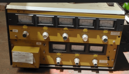
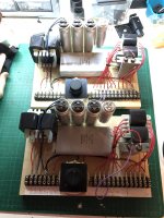
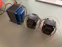
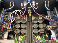
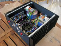
I have the iron already:
- Edcor PT with secondaries for 300 - 0 - 300V @ 200mA, 6.3V @ 4A and 5V @3A.
- Piemme Electra OTs, 25W Raa of 10k and UL taps at 35%.
- I have a quad of EHX 6V6GTs and a bunch of 12AX7, 12AT7s, 12AU7s, ECC99 and 6N1P which are available to use.
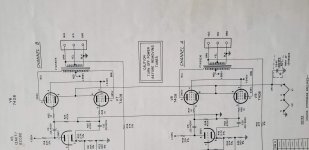
I’ve read most of the topic on the Baby Huey and also on other amps and did many LTSPice simulations. I have mostly settled on the Baby Huey scheme using fixed bias 6V6es, 12AX7 driver and source followers in between. For simplicity I would like to avoid the need for additional +56 or -48V supplies as used in some of the more recent Baby Huey schematics. I don’t have these windings on my PT and don’t want to include an extra additional transformer if possible. The Bias supply I plan to rectify from the HT winding as is done in many guitar amplifiers.
Here are my questions:
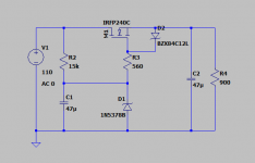
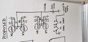
- Can I run the source followers from a filtered HT supply, with the source resistor going to ground instead of a negative supply? Would LND150 MOSFETs work? (As per the attached schematic?)
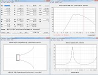
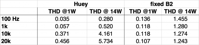
- I ran simulations using this scheme with LND150 source followers. THD figures are okay in the simulation with 0.5 % THD @14W and 1kHz. However, at higher frequencies THD increases dramatically. At 10k THD is 4.1% and at 20k it’s 5.7% (still at 14W output). What is the reason for this? What can I do about it? These values are determined without global negative feedback, using only the shunt feedback network. And of course the simulations are only as good as the models of the tubes and LND150 and I don’t know about their quality.
- With my PT the B+ will be more on the high side, probably around 380 - 390VDC. Should I think about running the 6V6s in cathode bias to reduce the plate-cathode voltage a bit towards the original specs?
- Would running the 6V6 with CCS cathode bias allow to ditch the source followers by increasing Rg1 to 470k?
- I still didn't really understand why the PI tubes need to be set to low current. I know this is kind of a pre-requisite for the Baby Huey arrangement, but I still don't really know why...? I have a couple of 6N1Ps I would like to use instead of 12AX7, but these need a current of around 3 - 4 mA per tube. However, 6N1Ps probably won't provide enough gain anyway.
- Do you have any other suggestions for me?
I’m open to other schemes but would like to use the iron and tubes I have. I’m not after the ultimate perfect HiFi experience but of course would love to build a decent sounding amp with the parts I have. I will run the amp with some old Heco speakers but may buy some more decent speakers later on.
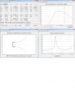
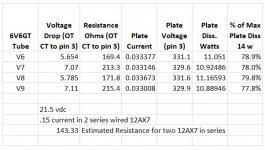
The attached schematics are those I’ve used for the simulation. Full 15W power output is achieved with an input signal of 1VRMS. I have attached a screenshot of a table I made which shows THD for different frequencies and different setups of the amp. “Huey” represents the shunt feedback method connecting the PI and finals anodes by resistors. “Fixed B2” represents the setup with powering the PI anodes of a fixed node in the supply (“B2”) and using global NFB.
As you can see, THD of the Huey arrangement is best at low frequencies but is increased at higher frequencies compared to the fixed HT version.
Thank you very much in advance for your support with that project. I'm looking forward to your suggestions.
Cheers,
Yves


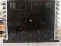


![DSC02975[8265].jpg](/community/data/attachments/974/974434-8bdcf7eb0983dc165d295f10d7889381.jpg?hash=i9z36wmD3B)
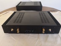
![DSC02977[8267].JPG](/community/data/attachments/974/974435-2a53b7e40da059b01ef86d9efffc10ad.jpg?hash=KlO35A2gWb)

