Hi all,
I’m looking for some advice on my first Hifi tube amp build. I’ve built several guitar tube amps already, so at least I know how to use the soldering iron, but I have no experience with low-THD audio builds, yet. Btw, I have learnt a lot from many discussions in this forum even though I have not participated actively until now. It's really a great resource!
I have looked into the various lowish power push-pull designs in the DIY community as for example, the Baby Huey, El Cheapo, Bevois Valley, ST-35 etc. I like the elegance of the Baby Huey but as I want to use 6V6 tubes, I don’t know if this will work? So I need your help here.
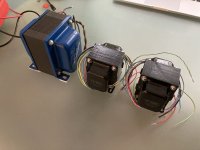
I have the iron already:
I’ve read most of the topic on the Baby Huey and also on other amps and did many LTSPice simulations. I have mostly settled on the Baby Huey scheme using fixed bias 6V6es, 12AX7 driver and source followers in between. For simplicity I would like to avoid the need for additional +56 or -48V supplies as used in some of the more recent Baby Huey schematics. I don’t have these windings on my PT and don’t want to include an extra additional transformer if possible. The Bias supply I plan to rectify from the HT winding as is done in many guitar amplifiers.
Here are my questions:
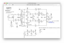
- Can I run the source followers from a filtered HT supply, with the source resistor going to ground instead of a negative supply? Would LND150 MOSFETs work? (As per the attached schematic?)
- I ran simulations using this scheme with LND150 source followers. THD figures are okay in the simulation with 0.5 % THD @14W and 1kHz. However, at higher frequencies THD increases dramatically. At 10k THD is 4.1% and at 20k it’s 5.7% (still at 14W output). What is the reason for this? What can I do about it? These values are determined without global negative feedback, using only the shunt feedback network. And of course the simulations are only as good as the models of the tubes and LND150 and I don’t know about their quality.
- With my PT the B+ will be more on the high side, probably around 380 - 390VDC. Should I think about running the 6V6s in cathode bias to reduce the plate-cathode voltage a bit towards the original specs?
- Would running the 6V6 with CCS cathode bias allow to ditch the source followers by increasing Rg1 to 470k?
- I still didn't really understand why the PI tubes need to be set to low current. I know this is kind of a pre-requisite for the Baby Huey arrangement, but I still don't really know why...? I have a couple of 6N1Ps I would like to use instead of 12AX7, but these need a current of around 3 - 4 mA per tube. However, 6N1Ps probably won't provide enough gain anyway.
- Do you have any other suggestions for me?
I’m open to other schemes but would like to use the iron and tubes I have. I’m not after the ultimate perfect HiFi experience but of course would love to build a decent sounding amp with the parts I have. I will run the amp with some old Heco speakers but may buy some more decent speakers later on.
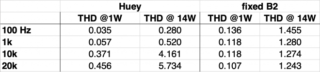
The attached schematics are those I’ve used for the simulation. Full 15W power output is achieved with an input signal of 1VRMS. I have attached a screenshot of a table I made which shows THD for different frequencies and different setups of the amp. “Huey” represents the shunt feedback method connecting the PI and finals anodes by resistors. “Fixed B2” represents the setup with powering the PI anodes of a fixed node in the supply (“B2”) and using global NFB.
As you can see, THD of the Huey arrangement is best at low frequencies but is increased at higher frequencies compared to the fixed HT version.
Thank you very much in advance for your support with that project. I'm looking forward to your suggestions.
Cheers,
Yves
I’m looking for some advice on my first Hifi tube amp build. I’ve built several guitar tube amps already, so at least I know how to use the soldering iron, but I have no experience with low-THD audio builds, yet. Btw, I have learnt a lot from many discussions in this forum even though I have not participated actively until now. It's really a great resource!
I have looked into the various lowish power push-pull designs in the DIY community as for example, the Baby Huey, El Cheapo, Bevois Valley, ST-35 etc. I like the elegance of the Baby Huey but as I want to use 6V6 tubes, I don’t know if this will work? So I need your help here.
I have the iron already:
- Edcor PT with secondaries for 300 - 0 - 300V @ 200mA, 6.3V @ 4A and 5V @3A.
- Piemme Electra OTs, 25W Raa of 10k and UL taps at 35%.
- I have a quad of EHX 6V6GTs and a bunch of 12AX7, 12AT7s, 12AU7s, ECC99 and 6N1P which are available to use.
I’ve read most of the topic on the Baby Huey and also on other amps and did many LTSPice simulations. I have mostly settled on the Baby Huey scheme using fixed bias 6V6es, 12AX7 driver and source followers in between. For simplicity I would like to avoid the need for additional +56 or -48V supplies as used in some of the more recent Baby Huey schematics. I don’t have these windings on my PT and don’t want to include an extra additional transformer if possible. The Bias supply I plan to rectify from the HT winding as is done in many guitar amplifiers.
Here are my questions:
- Can I run the source followers from a filtered HT supply, with the source resistor going to ground instead of a negative supply? Would LND150 MOSFETs work? (As per the attached schematic?)
- I ran simulations using this scheme with LND150 source followers. THD figures are okay in the simulation with 0.5 % THD @14W and 1kHz. However, at higher frequencies THD increases dramatically. At 10k THD is 4.1% and at 20k it’s 5.7% (still at 14W output). What is the reason for this? What can I do about it? These values are determined without global negative feedback, using only the shunt feedback network. And of course the simulations are only as good as the models of the tubes and LND150 and I don’t know about their quality.
- With my PT the B+ will be more on the high side, probably around 380 - 390VDC. Should I think about running the 6V6s in cathode bias to reduce the plate-cathode voltage a bit towards the original specs?
- Would running the 6V6 with CCS cathode bias allow to ditch the source followers by increasing Rg1 to 470k?
- I still didn't really understand why the PI tubes need to be set to low current. I know this is kind of a pre-requisite for the Baby Huey arrangement, but I still don't really know why...? I have a couple of 6N1Ps I would like to use instead of 12AX7, but these need a current of around 3 - 4 mA per tube. However, 6N1Ps probably won't provide enough gain anyway.
- Do you have any other suggestions for me?
I’m open to other schemes but would like to use the iron and tubes I have. I’m not after the ultimate perfect HiFi experience but of course would love to build a decent sounding amp with the parts I have. I will run the amp with some old Heco speakers but may buy some more decent speakers later on.
The attached schematics are those I’ve used for the simulation. Full 15W power output is achieved with an input signal of 1VRMS. I have attached a screenshot of a table I made which shows THD for different frequencies and different setups of the amp. “Huey” represents the shunt feedback method connecting the PI and finals anodes by resistors. “Fixed B2” represents the setup with powering the PI anodes of a fixed node in the supply (“B2”) and using global NFB.
As you can see, THD of the Huey arrangement is best at low frequencies but is increased at higher frequencies compared to the fixed HT version.
Thank you very much in advance for your support with that project. I'm looking forward to your suggestions.
Cheers,
Yves
Attachments
Thank you both for your suggestions!
@Steve Morley: I came across the Tubelab SPP before and it seems to be a nice amp. I don't know if the 12AT7 will provide enough gain to drive the 6V6s to full power though. I will definitely check it out with LTSpice")
@baudouin0: I would prefer to use mosfets for the buffering task as they are small and easy to put in the circuit. However, I simulated the circuit using an E88CC model configured as cathode follower in place of the mosfets but this didn't improve the THD figure. Again, of course I don't know about the quality of the models, but the high THD issue seems to be related to the feedback method as it appears consistently also using different tube models or mosfets.
Any more suggestions are as well appreciated. Thanks!
@Steve Morley: I came across the Tubelab SPP before and it seems to be a nice amp. I don't know if the 12AT7 will provide enough gain to drive the 6V6s to full power though. I will definitely check it out with LTSpice
@baudouin0: I would prefer to use mosfets for the buffering task as they are small and easy to put in the circuit. However, I simulated the circuit using an E88CC model configured as cathode follower in place of the mosfets but this didn't improve the THD figure. Again, of course I don't know about the quality of the models, but the high THD issue seems to be related to the feedback method as it appears consistently also using different tube models or mosfets.
Any more suggestions are as well appreciated. Thanks!
@kodabmx uses a 6F12P (~ECF80) with the pentode doing the amplifying, and a concertina splitter. Seems to work quite well. 6V6 and El84 are very easy to drive, not sure why would one need a follower unless you are friving them into grid current.Thank you both for your suggestions!
@Steve Morley: I came across the Tubelab SPP before and it seems to be a nice amp. I don't know if the 12AT7 will provide enough gain to drive the 6V6s to full power though. I will definitely check it out with LTSpice
@baudouin0: I would prefer to use mosfets for the buffering task as they are small and easy to put in the circuit. However, I simulated the circuit using an E88CC model configured as cathode follower in place of the mosfets but this didn't improve the THD figure. Again, of course I don't know about the quality of the models, but the high THD issue seems to be related to the feedback method as it appears consistently also using different tube models or mosfets.
Any more suggestions are as well appreciated. Thanks!
In previous sims I've done, the Baby Huey feedback arrangement has generally had higher distortion than the equivalent gain global NFB conventional arrangement. The LND150 is probably not the best choice for source follower, it's being a bit stretched at 4 mA and 110V, why not use the ZVN0545 as used in the original? The source follower wuold ideally be direct connected to the 6V6 grids, but you didn't want the extra supply voltages required for that. But where you've got it it's still doing a useful job unloading the ECC83 - distortion would be even worse if the ECC83 was directly driving the 100k grid resistor. As you say, with cathode bias and a 470k grid resistor, the source followers could be dropped. That would also reduce the effective plate voltage for the 6V6 which is quite high at the moment.
The low current (and ECC83) recommended for the PI is because a high plate resistance is required to maximise the benefit of the schade feedback. An ideal device here is a pentode but you don't see that very often.
The low current (and ECC83) recommended for the PI is because a high plate resistance is required to maximise the benefit of the schade feedback. An ideal device here is a pentode but you don't see that very often.
6F12P is like no other tube. ECF80 is way different, but probably the closest, and I haven't found any other tube with the same pinout as 6F12P.
Also I do use the pentode for amplifiying but it's strapped as a triode...
I can make a 6F12P and a 6N8S swing almost 300V into an output stage (with 600V B+)
Here it is since it's open source: C1 and C3 look too large, but it makes LF stability - no "breathing".

I use it to drive trioded sweep tubes (literally any sweep tubes). It would also drive a 6AS7G stage even if it was configured as a cathode follower output
It works very well with the Triad interleaved PT as OPT system I use, too. Those transformers have less phase shift than typical purpose wound EI OPTs, so more gNFB can be used without the concern of it turning positive.
A and B to to the output stage grids, I use 100k grid resistors.
I get the 600V it needs from a quadrupler from 120V isolation, the main tubes run from a doubler for 300V (double-quad)... but you could also do single-double from 230V.
Here's the double-quad is anyone is interested. It works and it's cheap.

990 and 660 are made of 330 caps in parallel...
Also I do use the pentode for amplifiying but it's strapped as a triode...
I can make a 6F12P and a 6N8S swing almost 300V into an output stage (with 600V B+)
Here it is since it's open source: C1 and C3 look too large, but it makes LF stability - no "breathing".
I use it to drive trioded sweep tubes (literally any sweep tubes). It would also drive a 6AS7G stage even if it was configured as a cathode follower output
It works very well with the Triad interleaved PT as OPT system I use, too. Those transformers have less phase shift than typical purpose wound EI OPTs, so more gNFB can be used without the concern of it turning positive.
A and B to to the output stage grids, I use 100k grid resistors.
I get the 600V it needs from a quadrupler from 120V isolation, the main tubes run from a doubler for 300V (double-quad)... but you could also do single-double from 230V.
Here's the double-quad is anyone is interested. It works and it's cheap.
990 and 660 are made of 330 caps in parallel...
Last edited:
@tikiroo : Thanks a lot for your thoughts! So, your suggestion would be to either use another source follower arrangement or to go cathode bias and drop the source followers? In the first case, why can't I run the ZN0545 mosfets from the HT supply? They have a Vd-s(max) of 450V so this should be fine, no? Why is this "intermediate" supply voltage (+56V / - 48V) used at all? And where did you get the numbers of 4mA and 110V? (sorry for my ignorance, I've been working with rather simple guitar amps until now). Would you suggest to leave out the anode feedback completely and fine tune the THD with global nfb only? As indicated by the table I posted this will increase the THD at lower frequencies but will have lower THD over the whole relevant frequency range.
@kodabmx : Thanks for all these information! This looks like a cool circuit indeed. I don't have these tubes available and no experience at all with these. Additionally, the circuit — even though I believe from your description it's performance will be really nice — is relatively complex compared to the circuits I was considering for the build. So I'll take this as food for thought but probably won't go this way with my current project. But thank you very much anyway!
@kodabmx : Thanks for all these information! This looks like a cool circuit indeed. I don't have these tubes available and no experience at all with these. Additionally, the circuit — even though I believe from your description it's performance will be really nice — is relatively complex compared to the circuits I was considering for the build. So I'll take this as food for thought but probably won't go this way with my current project. But thank you very much anyway!
If source followers are used to directly couple to the fixed bias output stage (as per the versions published in the baby huey threads), the source will sitting at the bias voltage (-33V in your sim) and will swing down to double that (-66) and up to 0 (or a bit higher if you go AB2). So negative supply has to be more negative than that (say -80V). Positive supply only needs to be enough to keep the input capacitance low (typically Vds>30). So if you swing the source to +10 then you would need +40 supply. Any higher gives no advantage and just increases the power dissipation. So you could connect to HT but you would need a mosfet with high enough dissipation rating.
The 110V was read from your schematic (Vd = 304V, Vg~Vs = 194V). With Vs =194V and a 47k source resistor, current must be 4.1 mA.
I wouldn't worry too much about the distortion numbers, plenty of people like how the baby huey sounds. If you want to try a more conventional arrangement, a triode or pentode directly coupled to a concertina phase splitter, capacitor coupled to the 6V6's, with global NFB would be easiest (as mentioned a couple of times in other replies). You get double the gain of the same tube used in a LTP, so a 12AT7 would work OK.
Being 6V6GT supposed to work in class AB2, I would DC couple the driver to the grid of the output tubes.
LND150 is not the best mosfet as source follower, and I'd stick on the BH original ones.
How much current flows through it?
Also consider that CCS loading the mosfet will improve its performance over a 47k.
I'd lower B+ by 50V and then the two feedback resistors 39k to 33k.
I prefer the 6V6GT with 8k and 23% UL (this was also the optimal suggested on old documents).
I just completed a Baby Huey based more closely on Yve's original, without source followers, described here ...
ECL86 Baby Huey
It sounds very sweet!
Are you aiming for a point to point build? I ended up using a 6V PCB mounted transformer for the negative rail, just because I wanted to use parts I had at hand.
ECL86 Baby Huey
It sounds very sweet!
Are you aiming for a point to point build? I ended up using a 6V PCB mounted transformer for the negative rail, just because I wanted to use parts I had at hand.
Hey all, sorry for taking so long to reply!
Again, thanks for these insightful answers!
@tikiroo : Now it makes total sense to me, thanks a lot for the explanation!
@zintolo : Thanks for your thoughts. I'll stick with my 10k UL transformers. I did some loadline drawing before ordering these and liked the 10k. 10k also gave slightly better performance in the simulation. And to be honest, I like to do stuff differently from time to time and I figured that 8k is used 95% in 6V6/EL84 builds.
@OldHector : Sweet build! I will do a combination of PTP and eyelet-board. That's what I'm used to do and when doing guitar amps I always came up with nice layouts after putting some thought into it.
So, I think I will stick with the basic Huey/El Cheapo topology: CCS loaded LTPI driving the PP 6V6s. For some reason I like the elegance and symmetry of this circuit. However, the arrangement using 1 pre- and 2 power-tubes would make changing to another topology easy, if desired.
As the B+ will be quite high probably, I'll start with a cathode biased arrangement and 470k grid-resistors. However, I'll leave space on the boards to implement directly coupled source followers in case I want to try that. I will get the negative rail for the PI CCS from half wave rectifying the HT winding and use large values resistors to get the right voltage. So I'll probably aim for -90V here (for negative rail of source followers) and take branches from that node to set the negative CCS voltage and a negative bias voltage, in case I want to use that later. I could even leave the cathode bias of the 6V6s in place and set the negative bias on the directly coupled source follower to ~0V. This yields good results in the simulation at least.
Can you recommend some suited mosfets that would have high enough dissipation limits to be run from HT to -90V and are suited for audio use?
Regarding the feedback arrangement: I will probably start the build using a fixed B1 voltage for the PI (and MOSFETS, if used) and global NFB. Changing to the anode feedback arrangement is relatively easily done if I want to try that later.
So, please feel free to comment on my thoughts. If there are no major complaints I'll draw up a schematic later to be used as a starting point for the build.
Thanks!
Suitable mosfets (from the EL34 baby huey thread):
FQPF2N60C
STF2N80K5
STU9HN65M2
STF7N60M2
Basically any TO-220 type NMOS with >600V Vds max and low and stable Crss (reverse transfer capacitance) when Vds>~20V.
Will be interesting to see what you come up with. My first build was an El Cheapo with 12AT7 LTP driving triode connected 7591s. I kept that for quite a while until I needed/wanted more power.
FQPF2N60C
STF2N80K5
STU9HN65M2
STF7N60M2
Basically any TO-220 type NMOS with >600V Vds max and low and stable Crss (reverse transfer capacitance) when Vds>~20V.
Will be interesting to see what you come up with
. My first build was an El Cheapo with 12AT7 LTP driving triode connected 7591s. I kept that for quite a while until I needed/wanted more power.To have good performance at high frequencies you need to have current flowing through the mosfet, so not a good idea to have too much voltage through it.
On my 6V6GT BH I have around +50V and -100V. That are the maximum g1 I target plus 25V to keep the Crss low ans stable, and 3 times the bias voltage to ensure the mosfet is properly running all time and not hit the negative rail.
On my 6V6GT BH I have around +50V and -100V. That are the maximum g1 I target plus 25V to keep the Crss low ans stable, and 3 times the bias voltage to ensure the mosfet is properly running all time and not hit the negative rail.
Just to better explain the point: in the previous case we'll swing around 100Vpp. Consider we want to swing flawless up to 100 kHz so the drivers are not the bottleneck. The needed slewrate is 2 * pi * f = 20 * pi V/us.
Total input capacitance of the 6V6GT should be around 30 pF, let's consider 50 pF for safety.
C = q/V so C = i * (1/slewrate) so needed current to ensure that slewrate = pi mA
That would mean to use 180 Ohm as reference resistor for the driver's CCS, but you need to verify that the dissipated heat will stay within safe values for the components used there, and then compromise between heat and performance: 50 kHz can be acceptable, and will need only pi/2 mA.
The dissipated heat would then be 150 V * 1.57 mA = 235.5 mW
Hey all and apologies for my delayed response again. I wish I had more time for tube projects.
@zintolo : Thank you for these explanations! To be honest, I couldn't completely follow the details described above, but I'll look more into this. So the point is to allow sufficient current through the driver to drive the output tubes also at high frequencies? Or do you mean the source followers? Power dissipation could be mitigated by using TO220 transistor types for the CCS maybe...?
@tikiroo : Thanks a lot for these suggestions! I'll check which of those I can get in Germany.
Attached is a schematic that I came up with for now. It's a work-in-progress schematic and will probably undergo changes as the build evolves but it's good as a starting point. Especially the resistors in the B- networks will have to be adjusted upon testing. The "branching" resistors in the B1 and B- supplies indicate where I want to tap the respective supplies for the second channel.
Any comments regarding the schematic? Are there any major flaws? Comments on the power supply networks are also more than welcome. I'm used to guitar amp topologies and these are often a lot more simple.
Thanks a lot!
Attachments
iefes,
If your B+ is too high, you might try a Modified choke input supply.
Generalization:
Cap input supply DCV ~ 1.414 x Vrms
Choke input supply DCV ~ 0.9 x Vrms
Modified choke input supply, between 1.414 x Vrms and 0.9 x Vrms
How do you do a Modified choke input - use a small first input cap before the choke (I use between 0.5uF and 4uF, your mileage may vary).
Watch out for the magnetic fields from the choke, especially for choke input and modified choke input. Proper angular orientation and space away from the output transformers helps reduce the coupling of hum to the output.
Self bias for the 6V6 not only allows a higher g1 grid resistor, it helps to balance the DC current of the two 6V6 tubes, the output transformer will love that.
Just my opinions.
- Home
- Amplifiers
- Tubes / Valves
- advice needed for Huey-inspired 6V6PP amp